
Effects of monomer rigidity on the microstructures and properties of polyimide aerogels cross-linked with low cost aminosilane†
Shuai Wua,
Ai Du*a,
Shangming Huanga,
Wei Suna,
Gouqing Zua,
Youlai Xianga,
Conghang Lib and
Bin Zhou*a
aShanghai Key Laboratory of Special Artificial Microstructure Materials and Technology, Pohl Institute of Solid State Physics, Tongji University, Shanghai 200092, P. R. China. E-mail: zhoubin863@tongji.edu.cn; duai@tongji.edu.cn; Fax: +86 21 65986071; Tel: +86 21 65986071
bLaboratory of Space Mechanical and Thermal Integrative Technology, Shanghai Institute of Satellite Engineering, Shanghai 200240, P. R. China
First published on 12th February 2016
Abstract
Polyimide aerogels were formed from polyamide acid oligomers cross-linked by Si–O–Si network structures, which were derived from hydrolysis and condensation reactions of low cost bis(trimethoxysilylpropyl) amine (BTMSPA). To investigate the effects of the chemical structures on their properties and microstructures, polyimide aerogels produced using hybrid diamines with different rigidity are evaluated. It is found that polyimide aerogels with rigid building blocks (PI-RBs) have a density in the range of 0.245 to 0.300 g cm−3 depending on the uncontrollable shrinkage (27–36%), and high Young's modulus of 50–76 MPa. While polyimide aerogels with flexible building blocks (PI-FBs) exhibit lower shrinkage of 8–15%, lower density ranging from 0.124 to 0.172 g cm−3, and a lower modulus of 28–34 MPa. Their various performances are closely related to the nanostructure difference between the particulate PI-FBs and the fibrous PI-RBs. The diverse morphology has been attributed to the different rigidities of their repeat units. Over all, the obtained polyimide aerogels are all excellent high-temperature thermal insulation materials with low thermal conductivity of 0.033–0.049 W (mK)−1 at room temperature and 5% weight loss temperature at about 550 °C in N2.
Introduction
Aerogels are novel materials with three-dimensional open networks.1–3 Due to their many desirable properties, such as low density, high porosity, high specific surface area, low thermal conductivity, low dielectric constant, and high acoustic impedance, aerogels have achieved great success in many fields.3–7 However, for traditional silica aerogels, the poor mechanic property greatly restricts their widespread application.8–10 Meador and Leventis et al. have made a great contribution to strengthening the weak silica aerogel by crosslinking its skeletal framework with polymers such as epoxy, styrene, isocyanate, and cyanoacrylates.11–18 Unfortunately, these polymer reinforced silica aerogels have to work at about 150 °C and will failure in higher temperature environment.19Polyimide is well-known for enhanced thermal stability, excellent dielectric properties, good chemical resistances, and excellent mechanical properties owing to its high degree of structural planarity and strong intermolecular forces.20 Generally, linear polyimide aerogels were produced through the physical interaction between polymer chains, which tend to exhibit a high shrinkage, poor thermal stability, and unsatisfactory mechanic property. While the cross-linked polyimide aerogels have a much better performance for their covalently bonded network structures cross-linked through some multifunctional amines called cross-linkers.19–21
Polyimide aerogel cross-linked with 1,3,5-tris-(aminophenyl) benzene (TAPB) was reported by Ken et al. in 2007. They found a rich variety of nano porous structures in the resulting aerogels and put forward that the possible mechanism about the varied structures was the competitive progress of liquid–liquid phase separation and crystallization induced by the reactions of end-crosslinking and thermal imidization during gelation.22 High temperature thermal imidization process (∼200 °C) was of great significance for the formation of polyimide gels. However, the gels easily dissolved during the energy-consumed heating step, inducing the destruction of their frameworks.21 By a low temperature thermal imidization route, Leventis and co-workers had made many novel investigations on polyimide aerogels synthesized from dianhydrides and diisocyanates, dianhydrides and triisocyanates, and a norbornene end-capped diimide.23–25 However, polyimide aerogels prepared by their ways also exhibited some defects either in mechanic strength or in thermal stability. With a simple chemical imidization process, Meador et al. had made deep researches on the polyimide aerogels prepared by cross-linking anhydride end capped polyamide acid (PAA) oligomers with some cross-linkers, including 1,3,5-triaminophenoxybenzene (TAB), octa (aminophenoxy)-silsesquioxane (OAPS), 2,4,6-tris(4-aminophenyl) pyridine (TAPP) and 1,3,5-benzenetricarbonyl trichloride (BTC).26–30 However, these indispensable cross-linkers are always commercially unavailable or very expensive, which limit the large-scale production of the polyimide aerogels. Recently, grapheme oxide (GO) cross-linked polyimide aerogels were prepared to obtain some materials for strain sensor or supercapacitors, without taking a consideration on their most notable thermal insulation.31–33 However, the larger size of m-GO than that of the polyimide backbones may lead to heterogeneity in network.33 In addition, 3-aminopropyltrimethoxysilane (APTES) was also treated as cross-linker to fabricate the highly cross-linked polyimide aerogels by a miscellaneous process.34
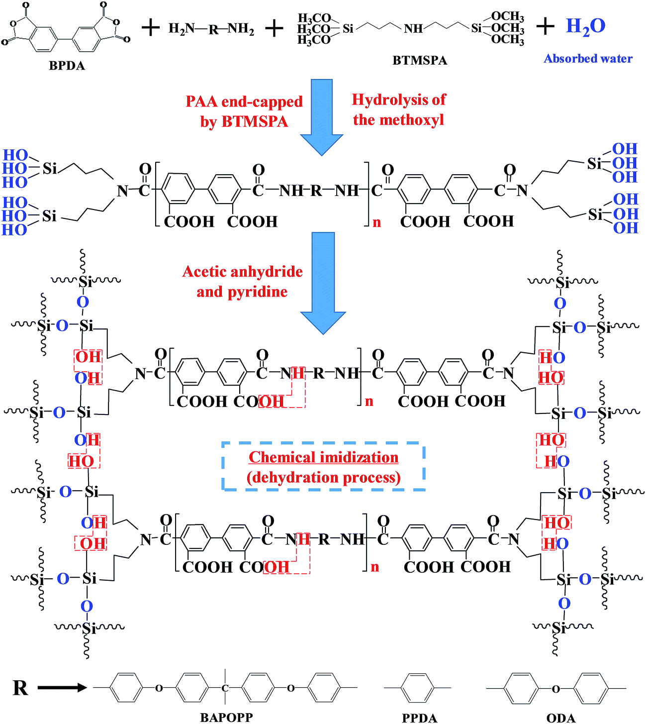
We successfully synthesized the polyimide cross-linked silica aerogels with the cross-linkers of bis(trimethoxysilylpropyl) amine (BTMSPA), but the gels easily cracked during aging process, which seriously lower the yield of the sample.35 In this study, polyimide aerogels were cross-linked by the Si–O–Si network structures, which are fabricated through the hydrolysis and condensation of the bis(trimethoxysilylpropyl) amine (BTMSPA) via the in situ water derived from the chemical imidization. Compared to the other cross-linkers, BTMSPA is lower cost, commercially available. As previously reported, the chemical structures of polyimide monomers can vastly affect the microstructures and properties of the obtained polyimide aerogels.23,25,29 Rigid diamine p-phenylenediamine (PPDA) and flexible diamine 4,4′-oxydianiline (ODA) were respectively used in combination with more flexible diamine, 2,2-bis[4-(4-aminophenoxy)phenyl] propane (BAPOPP) to fabricate polyimide aerogels with rigid building blocks (PI-RBs) and polyimide aerogels with flexible building blocks (PI-FBs). Effects of monomer rigidity on microstructures and properties of the aerogels, especially the thermal insulation, were studied by varying proportions of the hybrid diamines which were used to fabricate the oligomers as shown in Scheme 1.
 | ||
| Scheme 1 Synthesis of the PAA oligomers cross-linked with BTMSPA. | ||
Experimental
Materials
N-Methyl-2-pyrrolidinone (NMP), acetone, 4,4′-oxydianiline (ODA), pyridine and anhydrous acetic acid were purchased from Sinopharm ChemicalReagent Co. Ltd., China. Bis(trimethoxysilyl propyl) amine (BTMSPA), p-phenylenediamine (PPDA), 2,2-bis[4-(4-aminophenoxy) phenyl] propane (BAPOPP) and biphenyl-3,3′,4,4′-tetracarboxylic dianydride (BPDA) were purchased from Beijing InnoChem Science & Technology Co. Ltd., China. All reagents were used without further purification except dianhydride which needed to be dried at 125 °C for 24 h under vacuum before being used.Measurements
The bulk density of the aerogels were calculated from weight and volume of the cylindrical samples. Shrinkage was estimated via 100 × (mold diameter − sample diameter)/(mold diameter). Infrared spectra for the polyimide aerogels were obtained in KBr pellets using a Bruker Tensor-27 FT-IR spectrometer. The morphology of the aerogels were observed by scanning electron microscopy (SEM, Philips-XL30FEG). Samples were fractured at room temperature and sputter coated with gold before the SEM observation. The specific surface area and pore size distribution of the aerogels were obtained from nitrogen adsorption–desorption isotherms at 77 K, analyzed by using a Quantachrome Autosorb-1 analyzer. All samples were out-gassed by heating at 80 °C for 8 hours under a vacuum before collecting adsorption and desorption isotherm data by using nitrogen as the adsorbent at 77 K. The surface area of the sample was calculated by the Brunauer–Emmett–Teller (BET) method, and pore size distribution was determined by modeling using the BJH theory. Thermo gravimetric (TG) analysis was conducted from room temperature to 900 °C with a heating rate of 10 °C min−1 under nitrogen atmosphere on a TGA-7 instrument (Perkin Elmer, America). Thermal conductivity was measured on TPS 2500S thermal constants analyser (Hot Disk, Sweden) at room temperature and mean value was determined by three times measurements. The compression test was taken on a CMT 5105 universal materials testing machine under room conditions with a constant compression speed at 10% of the sample length per minute. Samples were polished smoothly using sandpapers to make sure that the top and bottom surfaces were parallel before installation between the two compression plates of the testing machine. The elastic modulus was taken as the slope of the initial linear portion in the obtained stress–strain curve of the compression.Preparation of polyimide aerogels
Polyamide acid (PAA) oligomers were prepared as previously reported. The molar ratio of dianhydride to total diamines is 26![[thin space (1/6-em)]](https://www.rsc.org/images/entities/char_2009.gif) :25. Diamines were consist of two of the three different diamines with different combination molar ratio, as show in Table 1. A sample procedure for an oligomer made from 100% BAPOPP and 300% ODA (indicating the molar ratio of the BAPOPP and ODA is 1:3) is as follow: BPDA (2.556 g, 8.7 mmol) was slowly added to a stirred solution of ODA (1254 g, 6.3 mmol) and BAPOPP (0.858 g, 2.1 mmol) in 38 ml NMP. The mixture was stirred for nearly 30 minutes until all the solids were dissolved, then the BTMSPA (225 μl, 0.68 mmol) was slowly added. The reaction mixture was vigorously stirred for 30 minutes, after which acetic anhydride (6.57 ml) and pyridine (5.62 ml) were added. The mixture solution was continually and vigorously stirred for 3 minutes, after which it was poured into a polytetrafluoroethylene mold. The gel was formed within different time (ten minutes to one week), depending on combinations of different diamines. The gel was removed from the mold after gelation, and soaked in fresh NMP to remove the acetic anhydride and pyridine. The solvent within the obtained gel was exchanged gradually over 24 hours intervals as follows: 75/25 vol% NMP/acetone, 50/50 vol% NMP/acetone and 25/75 vol% NMP/acetone, before being exchanged with 100% acetone three times and then dried by supercritical CO2 extraction.
:25. Diamines were consist of two of the three different diamines with different combination molar ratio, as show in Table 1. A sample procedure for an oligomer made from 100% BAPOPP and 300% ODA (indicating the molar ratio of the BAPOPP and ODA is 1:3) is as follow: BPDA (2.556 g, 8.7 mmol) was slowly added to a stirred solution of ODA (1254 g, 6.3 mmol) and BAPOPP (0.858 g, 2.1 mmol) in 38 ml NMP. The mixture was stirred for nearly 30 minutes until all the solids were dissolved, then the BTMSPA (225 μl, 0.68 mmol) was slowly added. The reaction mixture was vigorously stirred for 30 minutes, after which acetic anhydride (6.57 ml) and pyridine (5.62 ml) were added. The mixture solution was continually and vigorously stirred for 3 minutes, after which it was poured into a polytetrafluoroethylene mold. The gel was formed within different time (ten minutes to one week), depending on combinations of different diamines. The gel was removed from the mold after gelation, and soaked in fresh NMP to remove the acetic anhydride and pyridine. The solvent within the obtained gel was exchanged gradually over 24 hours intervals as follows: 75/25 vol% NMP/acetone, 50/50 vol% NMP/acetone and 25/75 vol% NMP/acetone, before being exchanged with 100% acetone three times and then dried by supercritical CO2 extraction.
| Treaction (°C) | Content (%) | Diamine types | Density (g cm−3) | Surface area (m2 g−1) | Shrinkage (%) | Young's modulus (MPa) | Thermal conductivity (W mK−1) | 5% weight loss (°C) |
|---|---|---|---|---|---|---|---|---|
| a BAPOPP fraction is 100% and other diamine is n%; that means the molar ratio between BAPOPP and other diamine is 100:n. |
||||||||
| 25 | 300 | ODA | 0.137 | 446 | 12.2 | 28.3 | 0.0334 | 547 |
| 25 | 100 | ODA | 0.124 | 357 | 8.2 | 32.3 | 0.0336 | 550 |
| 25 | 30 | ODA | 0.172 | 76 | 15.3 | 34.4 | 0.0492 | 560 |
| 25 | 0 | ODA | 0.246 | 29 | 15.7 | 84.4 | 0.0668 | 530 |
| 0 | 100 | PPDA | 0.300 | 351 | 35.7 | 49.8 | 0.0453 | 500 |
| 0 | 50 | PPDA | 0.284 | 174 | 32.6 | 76.7 | 0.0422 | 560 |
| 0 | 20 | PPDA | 0.245 | 237 | 26.5 | 55.7 | 0.0383 | 550 |
| 0 | 0 | PPDA | 0.246 | 29 | 15.7 | 84.4 | 0.0668 | 530 |
| 25 | 100 | PPDA | 0.564 | — | 43.8 | — | — | — |
| 25 | 50 | PPDA | 0.383 | — | 38.8 | — | — | — |
| 25 | 20 | PPDA | 0.482 | — | 40.8 | — | — | — |
Results and discussion
The detailed properties of BTMSPA cross-linked polyimide aerogels were list in Table 1. Polyimide aerogels were produced using a molar ratio of 26:25 between dianhydride and total diamines with different combinations in two systems. The reaction process was monitored by detecting the varied solution viscosity and evaluating the chemical groups in corresponding in situ infrared spectra in every stages. For in situ FTIR characterization, reaction solution in different stages were injected into the small gap between two silicon wafers for testing.
As shown in Fig. 1a, viscosity of the reaction solution was varied with reaction time in different stages during the gelation process. In the stage A1, hybrid diamines were dispersed homogeneously in NMP (38 ml) solvent. Viscosity of the solution stayed the same until dianhydride (BPDA) was added to fabricate polyamide acid (PAA) oligomers, which induced a relatively moderate increase of the viscosity in the stage A2. While after the BTMSPA (225 μl) was added, viscosity of the PAA solution with the BTMSPA was sharply raising up with a tendency of gelation in the stage A3. This indicated that the PAA oligomers were quickly end capped by the BTMSPA (as illustrated in Scheme 1). In the final stage A4 for the chemical imidization process, the viscosity was first dropping down for the dilution of acetic anhydride (6.57 ml) and pyridine (5.62 ml), and subsequently raising up to finish the gelation process (denoted by red dash line) within different times. Gelation time of the solution decreased with the increasing content of both flexible ODA in PI-FBs and rigid PPDA in PI-RBs, which were respectively used in combination with more-flexible BAPOPP. Meanwhile, gelation time of PI-RBs (within 10 minutes) was much shorter than PI-FBs (at least 30 minutes); while it took about one week for the solution produced only using BAPOPP to complete the gelation process, and the gels tend to re-dissolve during the solvent exchange process.
 | ||
| Fig. 1 (a-1, a-2) Viscosity-time curves; (b-1, b-2). corresponding FT-IR spectra for the chemical groups of the reaction solution in different stages; there was no difference on the variation tendency of viscosity and FT-IR spectra between PI-FBs and PI-RBs. | ||
From the infrared spectra as show in Fig. 1b, we can see the conversion process of PAA to PI clearly. Firstly, 1545 cm−1 attributed to the secondary amide (CONH) in PAA solution indicates the reaction between diamines and dianhydrides. Then in the chemical imidization process, peak at 1545 cm−1 disappear and peak at 1820 cm−1 arise (1820 cm−1 will shift to 1716 cm−1 after drying the gels). This is the direct evidence for the dehydration reaction between the hydrogen on the secondary amide (CONH) and the hydroxyl on the carboxylic acid (–COOH). However, we didn't find the peaks correspond the water (which is usually located at around 3400 cm−1 and 1630 cm−1), because the water were consumed by strong dehydration agent in this process.
After chemical imidization process, we can find the peak 1080 cm−1 which is attributed to the vibration of Si–O–Si in the polyimide aerogels.35 Si–O–Si in this reaction is derived from the hydrolysis and condensation reactions of BTMSPA. There was no additional water in the chemical imidization process. Thus, the BTMSPA should be hydrolysed before the chemical imidization. Since no additional water was added for the hydrolysis of BTMSPA, the water for the hydrolysis reaction should only be the absorbed moisture in the atmosphere. Shoulder peak at 1620 cm−1 in PAA solution and the PAA solution with BTMSPA may be ascribed to the absorbed water. Moreover, this shoulder peak did not appear in both diamines and dianhydrides solutions, this may because the moisture is easy to be absorbed by PAA solution.
However, the peak 1080 cm−1 didn't appeared when the BTMSPA was added in PAA. This may because acid environment in PAA is not favourable for the condensation reactions and dehydration agent in the imidization process accelerate the condensation reactions between hydrolyzed BTMSPA. The detailed reaction mechanism is illustrated in Scheme 1.
As seen in Fig. 2a, the combinations of diamines have great effects on the shrinkage. In comparison with some previously reported cross-linked polyimide aerogels, the BTMSPA cross-linked polyimide aerogels show lower shrinkage.26,27,29 Shrinkage of the samples prepared using only BAPOPP as diamine was about 16%, and decreased to a range of 15.3–8.2% after replacing BAPOPP with increasing ODA in PI-FBs. While the shrinkage of PI-RBs increased to 26.5–35.7% for the introduction of increasing PPDA. In the two systems, the majority of shrinkage was observed during aging process. Since the different shrinkages generally come from the combination of solvent interactions, chain rigidity and chain packing,29 there is no need to take a consideration on the solvent interactions in the two systems with the same solvent NMP.
 | ||
| Fig. 2 (a) Shrinkage and (b) density of the obtained polyimide aerogels. | ||
As previously reported, the non-coplanarity in the polyimide repeat units results in different relaxation, induces higher solubility and some microporosity.26,29 PPDA is a rigid monomer which tend to fabricate polyimide repeat units with a high degree of planarity. ODA is a flexible monomer due to its ether bond. BAPOPP is the most flexible monomer with two ether bonds, and two methyl groups which force the phenyl rings to be out of the plane with a torsional angle of 75°.26 For the gels derived from the diamine of BAPOPP, the two ether bonds in the monomer greatly decrease the rigidity of its building blocks.26 On the other hand, the methyl groups could also prevent the polymer chains packing together. Both of the two effects tend to accomplish a lower shrinkage, because the chain rigidity and chain packing become the main factors for the shrinkage of the polyimide gels.29 However, the high non-coplanarity of BAOPP also induces to the high solubility of the polyimide backbones, which lead to re-dissolving of the network structures of the gels.26,29 The collapse of the skeletons directly caused a large shrinkage. After replacing BAPOPP with less flexible ODA in PI-FBs, non-coplanarity of the monomers decrease, and the solubility of the polymer building blocks decrease. The weaken solubility of the building blocks has a positive influence on protecting the nanostructures and reducing the shrinkage (the shrinkage decrease from 16% to the range from 15.3–8.2%). However, the high shrinkage of PI-RBs (the shrinkage increase from 16% to the range from 26.5–37.5%) is mainly attributed to the close packing chains with highly rigid PPDA (as shown in SEM images in Fig. 5b), although the introduction of rigid PPDA in PI-RBs could prevent the destruction of the structures.
As noted in Table 1, shrinkage of the gels prepared at a reaction temperature (Treaction) of about 0 °C decreased by 30% compared to the gels produced at room temperature. Generally, phase separation for the polymer takes place when the molecular weight of oligomers exceeds a critical value. The oligomers of polyimide are formed by the polymerization reaction.37 The lower reaction temperature tend to slow down the polymerization process and prolong the time for the oligomers to turn in the supersaturated state. In other word, lower reaction temperature means a slower phase separation for the polyimide backbones. Therefore, slower phase separation process induced by lower temperature reaction tend to result in lower shrinkage. As discussed above, the gelation time of PI-RBs is much shorter than PI-FBs. It means that the PI-RBs undergo a quit fast phase separation in the imidization process for the introduction of PPDA. This can be another contribution to the high shrinkage of PI-RBs.
With a same trend of the shrinkage (as show in Fig. 2b), the density of PI-RBs (245 to 300 mg cm−3) was much higher than that of PI-FBs (124 to 172 mg cm−3). Since the solid fraction of the polyamide acid (PAA) precursor are almost the same, the density of the polyimide aerogels is inversely proportional to the volume, which is greatly depending on the shrinkage.
As show in Fig. 3, PI-FBs and PI-RBs have the same H1 hysteresis loop in their nitrogen absorption–desorption isotherms. The increasing of the volume adsorbed at relative pressure 0.9 and the narrow desorption hysteresis loop indicates the meso (2–50 nm) and macro porosity (over 50 nm). From the Fig. 4, we can see that the pore size of the obtained polyimide aerogels is mainly in the range of meso porous and macro porous. The distribution peak of PI-FBs locates from 25 nm to 35 nm, and PI-RBs have a low value of 12.5–25 nm. Based on the Brunauer–Emmett–Teller (BET) method, the specific surface areas and pore volume are determined by the nitrogen absorption–desorption isotherms (as list in Table 2). The BET specific surface area consists of the micro and meso porous specific area, because the macro pores can't be detected by the equipment. The majority of BET specific is attributed to the meso porous specific area for most of the samples except the one produced using only BAPOPP, which have the lowest BET specific surface area of 28.9 m2 g−1. After introduction of 30% ODA in PI-FBs, the BET specific surface area increases slightly to 76.1 m2 g−1. However, the introduction of 20 PPDA% in PI-RBs results in a significant increase of BET specific surface area to 236.8 m2 g−1. On the whole, introduction of both PPDA and ODA has increased the BET specific surface area and pore volume, as list in Table 2. This indicates that introduction of both rigid PPDA and flexible ODA into the most flexible BAPOPP has great effects on the pore structures.
 | ||
| Fig. 3 Nitrogen absorption–desorption isotherms of the obtained polyimide aerogels. | ||
 | ||
| Fig. 4 Pore-size distribution of the obtained polyimide aerogels. | ||
| Diamine types | Content (%) | SBETa (m2 g−1) | Vporeb (cm3 g−1) | Smicc (m2 g−1) | Dpored (nm) |
|---|---|---|---|---|---|
| a BET specific surface area was calculated by multipoint BET method.b Total pore volume was calculated by the single-point adsorption method.c Micro porous specific surface area was calculated by t-plot method.d Average pore diameter was calculated by the 4 × Vpore/σ method. | |||||
| ODA | 300 | 446.2 | 1.96 | 75.45 | 17.56 |
| ODA | 100 | 357.5 | 1.52 | 77.18 | 17.04 |
| ODA | 30 | 76.1 | 0.39 | 19.3 | 20.42 |
| ODA | 0 | 28.9 | 0.07 | 22.2 | 9.33 |
| PPDA | 100 | 351.1 | 1.09 | 54.18 | 12.40 |
| PPDA | 50 | 173.9 | 0.52 | 27.4 | 11.95 |
| PPDA | 20 | 236.8 | 1.20 | 53.67 | 20.26 |
| PPDA | 0 | 28.9 | 0.07 | 22.2 | 9.33 |
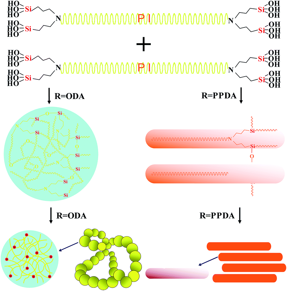
However, the SEM images (Fig. 5) show that their pore structures are quite different. The PI-FBs are particulate while the PI-RBs are fibrous. The diameter of the nano sized particle in PI-FBs and long straight fibrous in PI-RBs is similar, but the sample produced using only BAPOPP have some much larger clusters (Fig. 5a4 and b4). The Type H1 loop was reported for materials with assemblages of rigidly joint particles or cylindrical pore geometry.38 The PI-FBs are particulate and consist of joint particles, while PI-RBs are nano fibrous and tend to fabricate the cylindrical pore between two long straight chains. Both of the two nano structure could exhibit the Type H1 loop in their in their nitrogen absorption–desorption isotherms. Thus, polyimide aerogels in the two systems have different nanostructures, but the same corresponding hysteresis loops.
 | ||
| Fig. 5 SEM images of the obtained polyimide aerogels. | ||
As discussed above, gels produced only using BAPOPP are easy to re-dissolve and leads to a destruction of their frameworks. The broken network structures tend to result in the inhomogeneity of microstructures. That's why there are many big clusters in the sample without ODA or PPDA (as show in Fig. 5a4 and b4). Moreover, the broken nano porous frameworks also lead to an extremely low adsorption volume. Introduction of both ODA and PPDA weaken the solubility of the backbones, and result in a more uniform and healthy nano porous framework (Fig. 5a1, a2, b2 and b3). It is noteworthy that PI-FBs with 30% ODA still have some big clusters, while PI-RBs with 20% PPDA presents uniform polymer chains. The difference between them is also attributed to their monomer rigidity, because the rigid PPDA is better at strengthening the easy re-dissolved nano porous structures than the flexible ODA. This can also be the reason for the big difference on their increase of BET specific surface area and pore volume, in comparison with the sample produced using only BAPOPP.
Furthermore, we discuss the difference on microstructures between the PI-FBs and PI-RBs. The main difference in the two systems is the hybrid diamines with different rigidity, it is reasonable to assume that the nanostructures of the polyimide aerogels are controlled by the monomer rigidity. As mentioned above, the planarity of the monomer has a great influence on the building blocks. In PI-RBs, introduction of rigid PPDA, with a high degree of planarity, induced a directional growth of the repeat units. These directional building blocks tend to build up the long straight nano fibrous chains. While monomers in PI-FBs are both non-coplanar, the flexible repeat units have more opportunities to meet together. Therefore, these chaotic building blocks are easy to form the structure like a ball of wool, namely, the particulate nano structures. A possible mechanism is illustrated in Fig. 6.
 | ||
| Fig. 6 Possible evolution processes of the microstructures. | ||
Young's modulus of the aerogels was evaluated as the initial linear slope of the stress–strain curves. For the reason that the modulus is greatly depending on the density of the sample, the concepts of specific Young's modulus (E/ρ), and specific yield strength (δs/ρ) were used to compare their mechanic property.33 As listed in Table 3, the modulus of the aerogels fabricated only by BAPOPP is the highest (84.4 MPa), because the big clusters and dense nano structures tremendously strengthen the structure of the sample. PI-RBs have a higher modulus (49.8 to 76.7 MPa) than PI-FBs (28.3–34.4 MPa) for their rigid closely packing chains. Specific modulus of both PI-FBs and PI-FBs are comparable to the BTC cross-linked polyimide aerogels, which is much higher than the polyimide aerogels cross-linked by other cross-linkers.30 Meanwhile, the specific yield strength of PI-FBs was higher than that of PI-RBs. As show in Fig. S4,† PI-FBs were cut into many small cylindrical stanchions to strengthen the fragile silica aerogel, which indicated excellent mechanical process ability of the samples.
| Diamine types | Content (%) | ρ (g cm−3) | E (MPa) | E/ρ (J g−1) | Δs MPa | δs/ρ (J g−1) |
|---|---|---|---|---|---|---|
| ODA | 300 | 0.137 | 28.3 | 206.6 | 0.56 | 4.09 |
| ODA | 100 | 0.124 | 32.3 | 260.5 | 0.54 | 4.35 |
| ODA | 30 | 0.172 | 34.4 | 200.0 | 2.38 | 13.84 |
| ODA | 0 | 0.246 | 84.4 | 343.1 | 2.00 | 8.13 |
| PPDA | 100 | 0.300 | 49.8 | 166.0 | 0.54 | 1.80 |
| PPDA | 50 | 0.284 | 76.7 | 270.1 | 0.82 | 2.89 |
| PPDA | 20 | 0.245 | 55.7 | 227.4 | 0.33 | 1.35 |
| PPDA | 0 | 0.246 | 84.4 | 343.1 | 2.00 | 8.13 |
TGA was performed in N2 from room temperature to 900 °C without drying the samples before measurement. As shown in Fig. 7, weight loss at 100 °C for all the curves is about 2%, which represents the absorbed water of the samples. Since the pre-weight loss in the obtained polyimide aerogels is about 2%, the 5% weight loss points in the TGA curves should not correspond the actual 5% weight loss temperature of the samples. The actual 5% weight loss temperature of the polyimide aerogels should be corresponding to the point of around 7% in the TGA curves (detailed illustration for corresponding relationship was list in Fig. S5†). From the Table 1, we can see that most of the samples undergo a 5% weight loss at the temperature around 550 °C except the sample produced using only BAPOPP. The slight decrease in 5% weight loss temperature may also attributed to its broken nanostructures, which weaken the interaction of the polymer molecular chains. In addition, the sample produced with 100% PPDA has a 5% weight loss at the temperature of 500 °C, this may be due to the uncompleted imidization. Overall, the BTMSPA cross-linked polyimide aerogels have a high thermal stability.
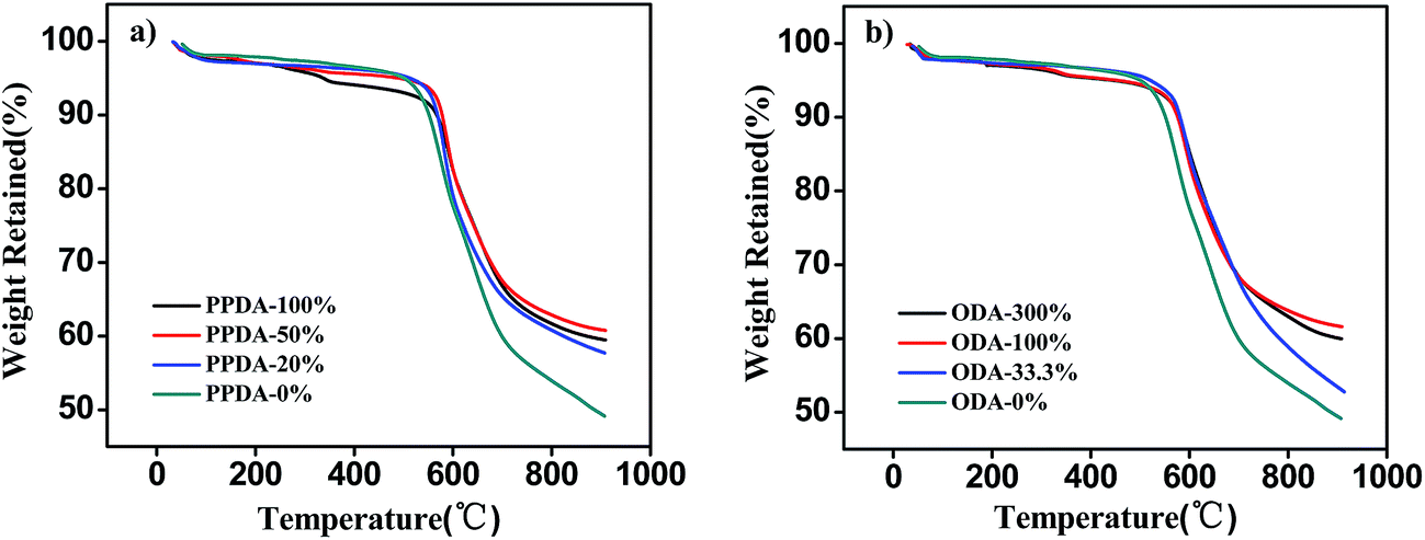 | ||
| Fig. 7 The TGA curves of the obtained polyimide aerogels. | ||
Thermal conductivity of the polyimide aerogels was measured at room temperature. It is seen in Fig. 8, polyimide aerogels prepared only using BAPOPP have the highest thermal conductivity of 0.067 W (mK)−1. The value significantly decreases after replacing the BAPOPP with the increasing amount of ODA in PI-FBs, and it retains at about 0.033 W (mK)−1 when the percentage of ODA is over 100%. While the thermal conductivity of PI-RBs first drops down to 0.038 W (mK)−1 dramatically for the introduction of 20% PPDA, and subsequent raises up to about 0.045 W (mK)−1 slowly with 100% PPDA.
 | ||
| Fig. 8 Thermal conductivity of the obtained polyimide aerogels. | ||
Theoretically, the total thermal conductivity of porous materials is the sum of the convective thermal conductivity kc, the radiative thermal conductivity kr, the solid thermal conductivity ks, and the gaseous thermal conductivity kg.39
| ktotal = kc + kr + ks + kg | (1) |
Since the pore size of the aerogel is in nanometer scale, the convective heat transfer between gas and solid phases can be neglected. Meanwhile, radiative thermal conductivity at ambient temperature gives little contribution to the total thermal conductivity.39,40 Therefore, the main contribution to the polyimide aerogel at ambient temperature is derived from λs, and λg.
| kambient = ks + kg | (2) |
Solid thermal conductivity can be written as follows:36,39
 | (3) |
The gaseous thermal conductivity of porous materials is frequently expressed as:36,39
 | (4) |
As mentioned above, the gels produced using only BAPOPP tend to have a broken porous structures and some big clusters. On one hand, broken porous networks decrease the uniform of the pore size. The non-uniformity of the pore size distribution increases, the number of the large pores also increases, and thus the heat transfer by the gas molecules will be enhanced.40 On the other hand, big clusters in the frameworks tend to decrease the interface thermal resistance and increase the solid thermal conductivity.39,40 Meanwhile, the re-dissolving of the gels also leads to high apparent density. As obvious from this eqn (3), high ρ means high solid thermal conductivity. But the apparent density is not the main contribution to the high total thermal conductivity of the sample only with BAPOPP. As show in Table 1, although PI-RBs with 20% PPDA has the similar density with the sample produced using only BAPOPP, its total thermal conductivity (0.038 W mK−1) is much lower than the later (0.067 W mK−1). Therefore, the high total thermal conductivity of the sample produced using only BAPOPP is mainly attributed to the destruction of its microstructures.
After replacing BAPOPP with ODA in PI-FBs and PPDA in PI-RBs, decreased solubility prevent the network frameworks being re-dissolved and sustain the uniform of the nanostructures. The improved uniform on both pore structure and particle size result in a low gas and solid thermal conductivity. Therefore, thermal conductivity of PI-FBs sustain decrease for the introduction of ODA. However, high apparent density here becomes the main contribution to the total thermal conductivity of PI-RBs. Take the samples with 20% and 100% PPDA for example, the two samples have similar BTE specific surface area and pore volume, which means a similar gas thermal conductivity. Therefore, the difference on their total thermal conductivity (the first one is 0.038 W mK−1 and the later one is 0.045 W mK−1) is mainly attributed to their diverse solid thermal conductivity. Since the chains diameter of the two samples is almost the same, which means the degree of contract vs is similar. In accordance with the eqn (3), the higher solid is mainly attributed to the higher density ρ.
In consider of the excellent mechanic strength and thermal insulation of the PI-FBs, samples with 300% ODA are embed as the stanchions into a piece of fiber reinforced silica aerogel (15 cm × 15 cm × 0.6 cm) to fabricate a thermal insulation component with highly mechanical strength. Thermal conductivity of the aerogel was measured on HFM436 thermal conductivity analyzer (NETZSCH, Germany), which is suitable for the samples with large area (at least 15 cm × 15 cm). Thermal conductivity of the polyimide aerogels can't be measured accurately by the instrument for their small areas. As show in Fig. S4,† the reinforced silica aerogel has a thermal conductivity of 0.018 W mK−1. After the polyimide aerogels were installed in, the thermal conductivity of the component was slightly raising to 0.020 W mK−1. While the modulus, as expected, can be tremendously improved by the high strength polyimide aerogels with a modulus of about 30 MPa. Compared to the traditional thermal insulation components in aerospace application, this device has a huge advantage on thermal insulation property for replacing some other stanchions with polyimide aerogels. Because the polyimide aerogels have much lower thermal conductivity than the other stanchions, like epoxy resin and aluminum material.
Conclusions
Polyimide aerogels were produced using the bis(trimethoxysilylpropyl) amine (BTMSPA) as the cross-linker instead of some expensive or commercially unobtainable ones. After hydrolysis and condensation reactions of BTMSPA, the Si–O–Si network structures were incorporated into the polyimide backbones derived from hybrid diamines with different rigidity. It is found the chain rigidity has great effects on the microstructures and properties of the obtained polyimide aerogels. Polyimide aerogels with flexible building blocks (PI-FBs) tend to form a silica aerogel like particulate nanostructures, while polyimide aerogels with rigid building blocks (PI-RBs) have long straight nano fibrous polymer chains. Moreover, PI-FBs have low shrinkage (8–15%), low density (0.124 to 0.172 g cm−3), high compression modulus (28–34 MPa), and low thermal conductivity (around 0.03 W mK−1). PI-RBs exhibits high density (0.245 to 0.300 g cm−3), high compression modulus (50–76 MPa) for their high shrinkage of 27–36%, and relative high thermal conductivity (about 0.04 W mK−1). Over all, the obtained polyimide aerogels have high thermal stability with onset decomposition at about 550 °C in N2. All the performance indicated a great potential for the polyimide aerogels with the cost effective cross-linker BTMSPA to expand from aerospace application to widespread fields.Acknowledgements
We are thankful for financial support from Bayer-Tongji Eco-Construction & Material Academy. National High Technology R&D Program of China (2013AA031801), National Natural Science Foundation of China (51172163), Science and Technology Innovation Fund of Shanghai Aerospace, China (SAST201321). We also thank Peng Yan for his assistance.References
- S. S. Kistler, Nature, 1931, 127, 741 CrossRef CAS.
- N. Hüsing and U. Schubert, Angew. Chem., Int. Ed., 1998, 37, 22–45 CrossRef.
- A. Du, B. Zhou, Z. Zhang and J. Shen, Materials, 2013, 6, 941–968 CrossRef CAS PubMed.
- M. A. B. Meador, E. McMillon, A. Sandberg and E. Barrios, ACS Appl. Mater. Interfaces, 2014, 6, 6062–6068 Search PubMed.
- A. P. Katsoulidis, J. Q. He and M. G. Kanatzidis, Chem. Mater., 2012, 24, 1937–1943 CrossRef CAS.
- A. Du, B. Zhou, W. Xu, Q. Yu, Y. Shen, Z. Zhang, J. Shen and G. Wu, Langmuir, 2013, 29, 11208–11216 CrossRef CAS PubMed.
- H. Sun, Z. Xu and C. Gao, Adv. Mater., 2013, 25, 2554–2560 CrossRef CAS PubMed.
- K. Kanamori, M. Aizawa, K. Nakanishi and T. Hanada, Adv. Mater., 2007, 19, 1589–1593 CrossRef CAS.
- G. Zhang, A. Dass, A. M. Rawashdeh, J. Thomas, J. A. Counsil, C. Sotiriou-Leventis, E. F. Fabrizio, F. Ilhan, P. Vassilaras, D. A. Scheiman, L. McCorkle, A. Palczer, J. C. Johnston, M. A. Meador and N. Leventis, J. Non-Cryst. Solids, 2004, 350, 152–164 CrossRef CAS.
- J. P. Randall, M. A. B. Meador and S. C. Jana, J. Mater. Chem. A, 2013, 1, 6642–6652 RSC.
- M. A. B. Meador, C. M. Scherzer, B. N. Nguyen, D. Quade and S. L. Vivod, ACS Appl. Mater. Interfaces, 2010, 2, 2162–2168 Search PubMed.
- M. A. B. Meador, L. A. Capadona, L. McCorkle, D. S. Papadopoulos and N. Leventis, Chem. Mater., 2007, 19, 2247–2260 CrossRef CAS.
- D. J. Boday, R. J. Stover, B. Muriithi, M. W. Keller, J. T. Wertz, K. A. D. Obrey and D. A. Loy, ACS Appl. Mater. Interfaces, 2009, 1, 1364–1369 Search PubMed.
- B. N. Nguyen, M. A. B. Meador, M. E. Tousley, B. Shonkwiler, L. McCorkle, D. A. Scheiman and A. Palczer, ACS Appl. Mater. Interfaces, 2009, 1, 621–630 Search PubMed.
- M. A. B. Meador, A. S. Weber, A. Hindi, M. Naumenko, L. McCorkle, D. Quade, S. L. Vivod, G. L. Gould, S. White and K. Deshpande, ACS Appl. Mater. Interfaces, 2009, 1, 894–906 Search PubMed.
- D. P. Mohite, Z. J. Larimore, H. Lu, J. T. Mang, C. Sotiriou-Leventis and N. Leventis, Chem. Mater., 2012, 24, 3434–3448 CrossRef CAS.
- N. Leventis, Acc. Chem. Res., 2007, 40, 874–884 CrossRef CAS PubMed.
- N. Leventis, C. Sotiriou-Leventis, G. Zhang and A. M. M. Rawashdeh, Nano Lett., 2002, 2, 957–960 CrossRef CAS.
- M. A. B. Meador, E. Malow, Z. He, L. McCorkle, H. Guo and B. N. Nguyen, Polym. Prepr., 2010, 51, 265–266 CAS.
- J. Lin, Y. Liu, W. Yang, Z. Xie, P. Zhang, X. Li, H. Lin, G. Chen and Q. J. Lei, J. Polym. Res., 2014, 21, 531–539 CrossRef.
- M. A. B. Meador, E. Malow, Z. He and L. McCorkle, Polym. Prepr., 2011, 52, 21–22 Search PubMed.
- K. Kawagishi, H. Saito, H. Furukawa and K. Horie, Macromol. Rapid Commun., 2007, 28, 96–100 CrossRef CAS.
- C. Chidambareswarapattar, Z. Larimore, C. Sotiriou-Leventis, J. T. Mang and N. Leventis, J. Mater. Chem., 2010, 20, 9666–9678 RSC.
- C. Chidambareswarapattar, L. Xu, C. Sotiriou-Leventis and N. Leventis, RSC Adv., 2013, 3, 26459–26469 RSC.
- N. Leventis, C. Sotiriou-Leventis, D. P. Mohite, Z. J. Larimore, J. T. Mang, G. Churu and H. B. Lu, Chem. Mater., 2011, 23, 2250–2261 CrossRef CAS.
- M. A. B. Meador, E. J. Malow, R. Silva, S. Wright, D. Quade, S. L. Vivod, H. Guo, J. Guo and M. Cakmak, ACS Appl. Mater. Interfaces, 2012, 4, 536–544 Search PubMed.
- H. Guo, M. A. B. Meador, L. McCorkle, D. J. Quade, J. Guo, B. Hamilton, M. Cakmak and G. Sprowl, ACS Appl. Mater. Interfaces, 2011, 3, 546–552 Search PubMed.
- D. Shen, J. Liu, H. Yang and S. Yang, Chem. Lett., 2013, 42, 1545–1547 CrossRef CAS.
- H. Guo, M. A. B. Meador, L. McCorkle, D. J. Quade, J. Guo, B. Hamilton and M. Cakmak, ACS Appl. Mater. Interfaces, 2012, 4, 5422–5429 Search PubMed.
- M. A. B. Meador, C. R. Alemaán, K. Hanson, N. Ramirez, S. L. Vivod, N. Wilmoth and L. McCorkle, ACS Appl. Mater. Interfaces, 2015, 7, 1240–1249 Search PubMed.
- Y. Zhang, W. Fan, Y. Huang, C. Zhang and T. Liu, RSC Adv., 2015, 5, 1301–1308 RSC.
- Y. Qin, Q. Peng, Y. Ding, Z. Lin, C. Wang, Y. Li, F. Xu, J. Li, Y. Yuan, X. He and Y. Li, ACS Nano, 2015, 9, 8933–8941 CrossRef CAS PubMed.
- Y. Ling, Y. Lu, W. Yao and X. Zhang, Acta Phys.–Chim. Sin., 2015, 31, 1179–1185 Search PubMed.
- X. Pei, W. Zhai and W. Zheng, Langmuir, 2014, 30, 13375–13383 CrossRef CAS PubMed.
- P. Yan, B. Zhou and A. Du, RSC Adv., 2014, 4, 58252–58259 RSC.
- G. Zu, J. Shen, W. Wang, L. Zou, Y. Lian, Z. Zhang, B. Liu and F. Zhang, Chem. Mater., 2014, 26, 5761–5772 CrossRef CAS.
- K. Wakabayashi, S. Kohama, S. Yamazaki and K. Kimura, Polymer, 2007, 48, 458–466 CrossRef CAS.
- M. Kruk and M. Jaroniec, Chem. Mater., 2001, 13, 3169–3183 CrossRef CAS.
- O. J. Lee, K. H. Lee, T. J. Yim, S. Y. Kim and K. P. Yoo, J. Non-Cryst. Solids, 2002, 298, 287–292 CrossRef CAS.
- G. H. Tang, C. Bi, Y. Zhao and W. Q. Tao, Energy, 2015, 90, 701–721 CrossRef CAS.
Footnote |
| † Electronic supplementary information (ESI) available: Digital images and response FT-IR spectra of the samples are provide to show the appearances and chemical composition. The stress–strain curves are provided to support the mechanical data analysis. Image and schematic diagram of the thermal insulation component is provided to show the application of the samples. See DOI: 10.1039/c5ra28152k |
| This journal is © The Royal Society of Chemistry 2016 |