Ni-based chromite spinel for high-performance supercapacitors

Xiaoyang Xua, Jianping Gao*ab and Wei Honga
aDepartment of Chemistry, School of Science, Tianjin University, China. E-mail: jianpinggaols@126.com
bCollaborative Innovation Center of Chemical Science and Engineering (Tianjin), Tianjin 300072, China

Received 29th December 2015 , Accepted 28th January 2016

First published on 29th January 2016


Abstract

NiCr2O4 has been prepared through the easy precipitation reaction of Ni2+ and Cr3+ (1[thin space (1/6-em)]:[thin space (1/6-em)]2 mol ratio) in aqueous NH3 followed by annealing at a high temperature. This is the first time that NiCr2O4 has been used as an electrode material for a supercapacitor. As expected, the NiCr2O4 exhibits good supercapacitive performance: at a current density of 0.6 A g−1, the specific capacitances of NiCr2O4 in the three-electrode and two-electrode setups are 422 and 187 F g−1, respectively; the energy density for the NiCr2O4 symmetric device reaches 6.5 W h kg−1 at a power density of 3000 W kg−1; and about 80% of the capacitance is retained after 2000 charge/discharge cycles. Therefore, research on NiCr2O4 as a supercapacitor material is necessary.

Introduction

Clean energy devices such as supercapacitors, fuel cells and rechargeable batteries are indispensable due to the continuous growth in environmental degradation and energy consumption.1 Supercapacitors have been applied in numerous fields2–7 due to their high energy and power densities, rapid charge/discharge and long lifetime.

Transition metal oxides have been developed as important components of electrode materials for supercapacitors. For example, many oxides of Ru,8 Ni,9 Co10 and Mn11 have exhibited good capacitive performances on account of their multiple oxidation states. However, some problems exist with these single metal oxides, including low specific capacitance and short cycling lifetime. Interestingly, mixed and binary metal oxides have been reported to have better electrochemical performances compared to single metal oxides12,13 due to their viable oxidation states and high electroconductivities.14,15 Therefore, binary metal oxides may be promising materials for supercapacitors.

Spinels have attracted ever-growing research interest from materials scientists due to their physico-chemical properties. Recently, chromite spinels have been used in many fields such as catalytic materials16–18 and gas sensors,19 and they occur as high-temperature oxidation products in Ni-containing alloys.20 As reported, chromite spinels have the general formula MCr2O4 (M = Ni, Co, Mn and so on), where the A-site is tetrahedrally coordinated and generally occupied by divalent cations such as Ni. The B-site is octahedrally coordinated and occupied by trivalent Cr cations. The binary metal oxide NiCr2O4 is a potential candidate for electrode materials in supercapacitors. However, to the best of our knowledge, there are no reports on the application of NiCr2O4 in supercapacitors.

In this work, NiCr2O4 was prepared through the easy precipitation reaction of Ni2+ and Cr3+ (1[thin space (1/6-em)]:[thin space (1/6-em)]2 mol ratio) in aqueous NH3 followed by annealing at high temperature. The prepared NiCr2O4 was used as the electrode material for supercapacitors. The electrochemical performances of the NiCr2O4 single electrode and the assembled NiCr2O4 symmetric device were investigated using cyclic voltammetry (CV), galvanostatic charge/discharge (GCD) cycles and electrochemical impedance spectroscopy (EIS) in the three-electrode and two-electrode setups.

Experimental

Materials

NiCl2·6H2O, Cr(NO3)3·9H2O, NH3·H2O, etc. were purchased from Tianjin Guangfu Chemical Reagent Co. All chemical reagents were used without any post-treatments.

Preparation of NiCr2O4

First, 0.02 mol of Cr(NO3)3·9H2O was dissolved in 100 mL of distilled water and stirred for about 30 min. Then, 50 mL of distilled water containing 0.01 mol of NiCl2·6H2O was added dropwise, and that solution was stirred for 30 min. NH3·H2O was added to adjust the pH of the solution to 12 in order to induce precipitation. After stirring for 3 h, the precipitate was separated, rinsed and dried to obtain a powder. The powder was then annealed in air for 2 h at the desired temperature (1000 °C, 850 °C or 700 °C).

Characterization

A BDX3300 X-ray diffractometer was used to study the X-ray diffraction (XRD) patterns.

Scanning electron microscopy (SEM) measurements were performed with a Hitachi Limited S4800 microscope (Japan).

An ethanol suspension of the sample was placed onto Cu grids, which were used for transmission electron microscopy (TEM) analysis on a Philips Tecnai G2F20 microscope.

Elemental analysis by X-ray photoelectron spectroscopy (XPS) was carried out on a PHI1600 ESCA System X-ray photoelectron spectrometer (PerkinElmer, US).

The N2 adsorption/desorption isotherms of the sample were collected on an NOVA 2000 automatic gas adsorption system (Quantachrome Company). The Brunauer–Emmett–Teller (BET) specific surface area and pore size distribution were assessed based on the desorption process and Barrett–Joyner–Halenda (BJH) method, respectively.

Electrochemical measurements

Three-electrode system. A three-electrode system was used to investigate the electrochemical performances of the NiCr2O4 single electrode. A suspension of the sample, carbon black and polytetrafluoroethylene solution was evenly coated onto Ni foam (1 × 1 cm2). After drying, the coated Ni foam was pressed to produce an electrode pad. The prepared electrode was used as the working electrode, a large-area Pt plate served as the auxiliary electrode and an Hg/HgO electrode was the reference electrode (Scheme 1a). The electrochemical activity of the electrode was evaluated by CV and GCD in 1 M KOH using a CHI660D workstation. The specific capacitances (Csp (F g−1)) were calculated as
 
image file: c5ra27931c-t1.tif(1)
where i (A) is the given discharge current, Δt (s) is the discharge time, Δν (V) is the applied potential window and m (g) is the mass of active materials.

image file: c5ra27931c-s1.tif
Scheme 1 Schematic illustrations of the three-electrode (a) and two-electrode (b) systems.
Two-electrode system. The NiCr2O4 symmetric device was assembled by combining two identical NiCr2O4 electrodes. The performance parameters of the device were assessed by CV, GCD cycles and EIS. In the EIS measurements, the frequency range was 10 mHz to 100 kHz, and the applied potential amplitude was 5 mV. The specific capacitances of the single electrode (Csp(s), F g−1) and device (Csp(d), F g−1) were calculated from eqn (2) and (3), respectively. The energy densities (E, W h kg−1) and power densities (P, W kg−1) were normalized to the mass of active materials in the two electrodes and estimated using eqn (4) and (5).
 
image file: c5ra27931c-t2.tif(2)
 
image file: c5ra27931c-t3.tif(3)
 
image file: c5ra27931c-t4.tif(4)
 
image file: c5ra27931c-t5.tif(5)

In the above equations, M (g) is the total mass of active material in both electrodes.

Results and discussion

Preparation of NiCr2O4

The Ni2+ and Cr3+ ions in aqueous NH3 produced a precipitate. The precipitate was annealed in air at different temperatures because annealing temperature plays an important role in the synthesis and structure of NiCr2O4. Just as reported, this simple wet precipitation method contains the hydroxide precipitation from metal ions in the presence of NH3·H2O or alkalis and calcinations for hydroxide precipitation.21

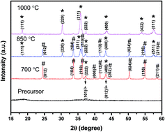
Fig. 1 shows the XRD patterns of the samples prepared at different annealing temperatures. Obviously, there are almost no peaks in the XRD pattern of the precipitate when it was not annealed, indicating amorphous character. The XRD pattern of the sample annealed at 1000 °C shows the characteristic peaks of NiCr2O4 (JCPDS card no. NiCr2O4 65-3105). The XRD pattern for the sample annealed at 850 °C has characteristic peaks for NiCr2O4 and Cr2O3 (JCPDS card no. Cr2O3 38-1479). The Cr2O3 peaks are dominant in the XRD pattern of the sample annealed at 700 °C. In addition, NiO should be also present in the samples annealed at 700 °C and 850 °C. For example, the diffraction peaks at about 24.5°, 33.6°, 36.2°, 39.7°, 41.5°, 44.2°, 50.2°, 54.9° and 57.1° are assigned to the (012), (104), (110), (006), (113), (202), (024), (116) and (211) crystal planes of Cr2O3, respectively. The other diffraction peaks at about 18.5°, 30.4°, 36.5°, 37.4°, 43.5°, 54.0° and 57.5° correspond to the (111), (220), (311), (222), (400), (422) and (511) crystal planes of NiCr2O4, respectively. However, the diffraction peaks corresponding to the (101) and (012) crystal planes of NiO (JCPDS card no. NiCr2O4 44-1159) are also at about 36.5° and 43.5°, respectively, causing them to overlap the NiO diffraction peaks. These results clearly indicate that the formation of NiCr2O4 depends on the annealing temperature; the temperature must reach at least 1000 °C to form pure NiCr2O4.


image file: c5ra27931c-f1.tif
Fig. 1 XRD patterns of the samples prepared at different annealing temperatures (#: Cr2O3; *: NiCr2O4; Δ: NiO).

The morphology and structure of the NiCr2O4 sample (the sample annealed at 1000 °C) were investigated by SEM and TEM. Fig. 2a shows the SEM image of the NiCr2O4 sample. It can be clearly observed that the NiCr2O4 sample is made up of tetragonal bipyramidal crystallites, which is in good agreement with the literature.22 TEM measurements of the NiCr2O4 sample were carried out, and the images are shown in Fig. 2b and c. The NiCr2O4 sample is composed of aggregated grains (Fig. 2b), and the high-resolution TEM image of NiCr2O4 shows clear lattice fringes (Fig. 2c), indicating the crystalline nature of the NiCr2O4 nanoparticles. The lattice fringe spacing is 0.26 nm, which is indicative of the (311) NiCr2O4 plane.


image file: c5ra27931c-f2.tif
Fig. 2 SEM (a) and TEM images (b and c) of the NiCr2O4 sample.

XPS analysis was also used to investigate the composition of the NiCr2O4 sample. The survey spectrum of the NiCr2O4 sample (Fig. 3a) contains elemental peaks for Ni, Cr, and O. The Ni[thin space (1/6-em)]:[thin space (1/6-em)]Cr atomic ratio is 1[thin space (1/6-em)]:[thin space (1/6-em)]1.98, which is on the verge of the stoichiometry in the molecular formula of NiCr2O4. In Fig. 3b, the Ni 2p core level spectrum was divided into two spin–orbit doublets and two shakeup satellites (Sat.) with a Gaussian fitting method. The peaks at 855.3 and 871.3 eV correspond to Ni2+, while the peaks at 856.3 and 874.1 eV are from Ni3+. The Cr 2p core-level spectrum (Fig. 3c) was also divided into two spin–orbit doublets characteristic of Cr2+ (576.4 and 588.1 eV) and Cr3+ (575.4 and 585.3 eV). These results are very similar with those reported for NiCo2O4.23


image file: c5ra27931c-f3.tif
Fig. 3 XPS survey spectrum (a) and Ni 2p (b) and Cr 2p (c) core-level spectra of the sample annealed at 1000 °C.

To determine the specific surface area and pore size, N2 adsorption/desorption isotherms of the NiCr2O4 sample were collected, and the results are shown in Fig. 4a. The isotherms for NiCr2O4 are type-IV with a hysteresis loop, indicating a typical mesoporous structure.24,25 The computational BET specific surface area of NiCr2O4 is 76.23 m2 g−1. In addition, the pore size distribution plots for NiCr2O4 based on the BJH desorption course are shown in Fig. 4b. NiCr2O4 possesses a predominantly mesoporous structure, making it easily exposed to electrolyte ions, which should lead to a fast charge-transfer rate.


image file: c5ra27931c-f4.tif
Fig. 4 N2 absorption/desorption isotherms (a) and pore size distribution (b) of NiCr2O4.

Electrochemical behavior of NiCr2O4

As discussed above, the formation of NiCr2O4 mainly depends on the annealing temperature. Since the sample annealed at 1000 °C is pure NiCr2O4, this sample was applied as a potential supercapacitor material. The CV curves of the NiCr2O4 electrode at different potential ranges in a three-electrode system are shown in Fig. 5a. It can be observed that the potential range of 0–0.65 V is more suitable due to the presence of redox peaks, which can lead to high capacitance. Therefore, the potential range of 0–0.65 V was used in the subsequent experiments. Fig. 5b shows typical CV curves of the NiCr2O4 electrode in the three-electrode setup. All the CV curves contain redox peaks, implying that the capacitances are mainly dominated by a faradaic redox mechanism.26 These redox reactions may be:27,28
 
NiCr2O4 + 3OH ↔ NiOOH + 2CrO2 + H2O + e (6)
 
CrO2 + 4OH ↔ CrO42− + 2H2O + 3e (7)
 
Ni(OH)2 + OH ↔ NiOOH + H2O + e (8)

image file: c5ra27931c-f5.tif
Fig. 5 CV curves for different potential ranges (a), CV curves for the potential range of 0–0.6 V (b), GCD curves (c), and specific capacitances calculated from the GCD curves (d) for the NiCr2O4 electrode using a three-electrode system.

At high scan rates, the shapes of the CV curves have no obvious distortion compared to the shapes at low scan rates. This indicates high-rate and excellent electron ion transport within the electrode material.29 Moreover, there is almost no change in the peak position upon cycling (Fig. S1).

As shown in Fig. 5c, the NiCr2O4 electrode exhibits nonlinear GCD curves, implying the faradaic redox reaction of NiCr2O4. This is in good agreement with the CV results. The specific capacitances of NiCr2O4 were calculated from the GCD curves (using eqn (1)), and the results are shown in Fig. 5d. The specific capacitances of NiCr2O4 are 422, 329, 298, 283, 268, 239 and 216 F g−1 at the current densities of 0.6, 1.2, 1.8, 2.4, 3, 4.5 and 6 A g−1. The specific capacitances of NiCr2O4 are higher than those for NiO (250 F g−1 at 0.5 A g−1 (ref. 30)), reduced graphene oxide/multi-walled carbon nanotubes/NiO (367 F g−1 at 1 A g−1 (ref. 31)) and Cr2O3 (291 F g−1 at 0.25 A g−1 (ref. 32) and 130 F g−1 at 1 A g−1 (ref. 33)). In addition, the specific capacitances of NiCr2O4 are also higher than those of some other binary metal oxides; for example, the reported specific capacitances of CoFe2O4 were 230, 218 and 187 F g−1 at the current densities of 0.2, 0.25 and 4 A g−1,34 respectively, and those of ZnFe2O4 were 36.7, 33.9 and 28.2 F g−1 at the current densities of 1, 2 and 5 A g−1,35 respectively. It is obvious that the specific capacitance decreases with increasing current density due to the slow diffusion/migration of protons into the electrodes at high current density.36

In order to realize practical applications, the NiCr2O4 symmetric device was assembled, and its electrochemical performance was investigated in a two-electrode setup. Compared with a three-electrode setup, the two-electrode setup often gives a lower capacitance value, but it is closer to the realistic value.37 In the assembled symmetric capacitor, two NiCr2O4 electrodes (cathode and anode) are separated by a porous matrix and immersed in 1 M KOH solution for analysis. Fig. 6a and b show the CV and GCD curves of the assembled NiCr2O4 symmetric device in the potential window from 0 to 1 V, respectively. The specific capacitances of the NiCr2O4 single electrode in the two-electrode system were calculated from the GCD curves using eqn (2) (Fig. 6c). The specific capacitance values are 187, 167, 156, 141, 126, 109 and 94 F g−1 at current densities of 0.6, 1.2, 1.8, 2.4, 3, 4.5 and 6 A g−1, respectively. The calculated specific capacitance of the NiCr2O4 symmetric device (using eqn (3)) is 42 F g−1 at a current density of 1.2 A g−1, higher than that for the NiO symmetric capacitor (34.9 F g−1 at a current density of 1 A g−1).38


image file: c5ra27931c-f6.tif
Fig. 6 CV curves (a) and GCD curves (b) for the assembled NiCr2O4 symmetric device; specific capacitances of the NiCr2O4 single electrode calculated from the GCD curves (c) in a two-electrode system.

In order to determine the lifetime of the assembled NiCr2O4 symmetric device, the capacitance retention of NiCr2O4 over 2000 cycles at 3 A g−1 was tested (Fig. 7a). After 2000 charge/discharge cycles, the NiCr2O4 symmetric device retained about 80% of its initial capacitance. This is higher than the retention values reported for other materials such as NiCo2S4 (77% after 2000 cycles),39 NiCo2O4 (72.7% after 2000 cycles)40 and NiMoO4@Ni(OH)2 (nearly 72% after 1000 cycles).41


image file: c5ra27931c-f7.tif
Fig. 7 Capacitance retention after 2000 charge/discharge cycles (a) and XRD patterns (b) of the NiCr2O4 electrode before and after charge/discharge cycles for the assembled NiCr2O4 symmetric device.

Capacitance loss with extended cycling is a common phenomenon in supercapacitors, and this loss is widely thought to be due to the loss of adhesion between the electrode and the substrate and the dissolution of the active materials into the electrolyte. The XRD patterns of the NiCr2O4 electrode (including NiCr2O4, carbon black and PTFE) before and after the charge/discharge cycles were used to study the structural changes, and the results are shown in Fig. 7b. The before and after XRD patterns are similar, indicating that the composition of the NiCr2O4 electrode did not change during the charge/discharge processes. The XPS test for the sample peeling off the electrode after cycling was also conducted. In Fig. S2, the Ni 2p and Cr 2p core-level spectra have almost no change compared with those before cycling. In addition, the SEM images of the NiCr2O4 electrode before and after the charge/discharge cycles are shown in ESI (Fig. S3). The images seem to suggest that the NiCr2O4 electrode particles tend to be more inhomogeneous after the charge/discharge cycles.

EIS measurements of the device before and after 2000 charge/discharge cycles were carried out to clearly analyze the capacitance loss. The resulting Nyquist plots are shown in Fig. 8a. The Nyquist plots clearly consist of a semi-circle (the charge-transfer resistance (Rct)) and a straight line (Warburg impedance) in the high- and low-frequency sections, respectively.42 In the high-frequency range, the real axis intercept is slightly larger after the long-term charge/discharge test, indicating a higher internal resistance with increasing number of charge/discharge cycles. The low Rct demonstrates a low charge transfer resistance.43 The nearly perpendicular straight line to the real axis suggests a low Warburg resistance, which facilitates the diffusion of electrolyte ions into the electrode materials and leads to a facile and reversible faradaic redox. Bode plots of impedance phase angle versus frequency obtained from EIS are also shown in Fig. 8b. The relaxation time constant could be derived from the characteristic frequency at a phase angle of −45°. The relaxation time also becomes slightly greater after the charge/discharge cycles.


image file: c5ra27931c-f8.tif
Fig. 8 Nyquist plot (a), Bode plot (phase angle versus frequency) (b) and Ragone plot (c) of the assembled NiCr2O4 symmetric device.

The energy densities for the NiCr2O4 symmetric device were calculated at different power densities using eqn (4) and (5), and the Ragone plots of energy and power densities are given in Fig. 8c. The energy density of the NiCr2O4 symmetric device was 6.5 W h kg−1 at a power density of 3000 W kg−1 and decreases with increasing power density. At a high power density of 3100 W kg−1, the energy density still reached 3.3 W h kg−1. The energy density of the NiCr2O4 symmetric device is higher than those of other reported materials, such as an Mn3O4 symmetric capacitor (4.36 × 10⁻² W h kg−1),44 Co3O4 symmetric capacitor (2.42 W h kg−1)45 and Ni(OH)2/CuO symmetric capacitor (1 W h kg−1).46

Conclusions

NiCr2O4 was successfully prepared through the easy precipitation reaction of Ni2+ and Cr3+ (1[thin space (1/6-em)]:[thin space (1/6-em)]2 mol ratio) in aqueous NH3 followed by annealing at 1000 °C. The prepared NiCr2O4 nanoparticles were then used for the first time as the electrode materials in supercapacitors and exhibited good supercapacitive performances. The specific capacitances of NiCr2O4 in the three-electrode and two-electrode systems were 422 and 187 F g−1, respectively, at 0.6 A g−1. The capacitance retention of the NiCr2O4 symmetric device was about 80% after 2000 charge/discharge cycles, and the energy density of the NiCr2O4 symmetric capacitor was 6.5 W h kg−1 at a power density of 3000 W kg−1. Therefore, NiCr2O4 is a very promising electrode material for energy storage.

Acknowledgements

This work was supported by the National Science Foundation of China (21074089, 21276181).

References

  1. H. C. Chien, W. Y. Cheng, Y. H. Wang and S. Y. Lu, Adv. Funct. Mater., 2014, 22, 5038–5043 CrossRef.
  2. B. E. Conway, Electrochemical Supercapacitors, Scientific Fundamentals and Technological Applications, Kluwer Academic/Plenum Press, New York, 1999 Search PubMed.
  3. B. E. Conway, J. Electrochem. Soc., 1991, 138, 1539–1548 CrossRef CAS.
  4. S. Sarangapani, B. V. Tilak and C. P. Chen, J. Electrochem. Soc., 1996, 143, 3791–3799 CrossRef CAS.
  5. A. Burke, J. Power Sources, 2001, 91, 37–50 CrossRef.
  6. G. P. Wang, L. Zhang and J. J. Zhang, A review of electrode materials for electrochemical supercapacitors, Chem. Soc. Rev., 2012, 41, 797 RSC.
  7. J. P. Zheng, P. J. Cygan and T. R. Jow, J. Electrochem. Soc., 1995, 142, 2699–2703 CrossRef CAS.
  8. R. R. Bi, X. L. Wu, F. F. Cao, L. Y. Jiang, Y. G. Guo and L. J. Wan, J. Phys. Chem. C, 2010, 114, 2448–2451 CAS.
  9. S. K. Meher, P. Justin and R. G. Rao, ACS Appl. Mater. Interfaces, 2011, 3, 2063–2073 CAS.
  10. X. H. Xia, J. P. Tu, Y. J. Mai, X. L. Wang, C. D. Gu and X. B. Zhao, J. Mater. Chem., 2011, 21, 9319–9325 RSC.
  11. J. Zhu, W. Shi, N. Xiao, X. Rui, H. Tan, X. Lu, H. H. Hng, J. Ma and Q. Yan, ACS Appl. Mater. Interfaces, 2012, 4, 2769–2774 CAS.
  12. S. H. Kim, Y. I. Kim, J. H. Park and J. M. Ko, Int. J. Electrochem. Sci., 2009, 4, 1489–1496 CAS.
  13. J. K. Chang, M. T. Lee, C. H. Huang and W. T. Tsai, Mater. Chem. Phys., 2008, 108, 124–131 CrossRef CAS.
  14. Y. Q. Wu, X. Y. Chen, P. T. Ji and Q. Q. Zhou, Electrochim. Acta, 2011, 56, 7517–7522 CrossRef CAS.
  15. T. Y. Wei, C. H. Chen, H. C. Chien, S. Y. Lu and C. C. Hu, Adv. Mater., 2010, 22, 347–351 CrossRef CAS PubMed.
  16. N. J. Jebarathinam, M. Eswaramoorthy and V. Krishnasamy, Bull. Chem. Soc. Jpn., 1994, 67, 3334–3338 CrossRef CAS.
  17. J. Sloczynski, J. Ziolkowski, B. Grzybowska, R. Grabowski, D. Jachewicz, K. Wcislo and L. Gengembre, J. Catal., 1999, 187, 410–418 CrossRef CAS.
  18. S. S. Acharyya, S. Ghosh and R. Bal, ACS Appl. Mater. Interfaces, 2014, 6, 14451–14459 CAS.
  19. C. L. Honeybourne and R. K. Rasheed, J. Mater. Chem., 1996, 6, 277–283 RSC.
  20. A. Strawbridge, F. H. Stott and G. C. Wood, Corros. Sci., 1993, 35, 852–855 CrossRef.
  21. R. Prasad and P. Singh, Bull. Chem. React. Eng. Catal., 2011, 6, 63–113 Search PubMed.
  22. S. Mircea, M. Barbu, P. Barvinschi and S. Oana, J. Therm. Anal. Calorim., 2013, 111, 1121–1127 CrossRef.
  23. K. B. Xu, X. J. Huang, Q. Liu, R. J. Zou, W. Y. Li, X. J. Liu, S. J. Li, J. M. Yang and J. Q. Hu, J. Mater. Chem. A, 2014, 2, 16731–16739 CAS.
  24. M. S. Balathanigaimani, W. G. Shim, M. J. Lee, C. Kim, J. W. Lee and H. Moon, Electrochem. Commun., 2008, 10, 868–871 CrossRef CAS.
  25. M. C. Liu, L. B. Kong, P. Zhang, Y. C. Luo and L. Kang, Electrochim. Acta, 2012, 60, 443–448 CrossRef CAS.
  26. X. Y. Xu, T. Wu, F. L. Xia, Y. Li, C. C. Zhang, L. Zhang, M. X. Chen, X. C. Li, L. Zhang, Y. Liu and J. P. Gao, J. Power Sources, 2014, 266, 282–290 CrossRef CAS.
  27. P. Skołuda, Electrochem. Commun., 2007, 9, 405–408 CrossRef.
  28. J. W. Xiao, L. Wan, S. H. Yang, F. Xiao and S. Wang, Nano Lett., 2014, 14, 831–838 CrossRef CAS PubMed.
  29. S. Biswas and L. T. Drzal, Chem. Mater., 2010, 22, 5667–5671 CrossRef CAS.
  30. Y. Jiang, X. J. Leng, Z. L. Jia, H. X. Chen, H. Suo and C. Zhao, J. Mater. Sci.: Mater. Electron., 2015, 26, 2995–3000 CrossRef CAS.
  31. R. Rajendran, L. K. Shrestha, R. M. Kumar, R. Jayavel, J. P. Hill and K. Ariga, J. Inorg. Organomet. Polym., 2015, 25, 267–274 CrossRef CAS.
  32. S. Ullah, I. A. Khan, M. Choucair, A. Badshah, I. Khan and M. A. Nadeema, Electrochim. Acta, 2015, 171, 142–149 CrossRef CAS.
  33. X. Y. Xu, J. Z. Wu, N. Yang, H. Y. Na, L. Z. Li and J. P. Gao, Mater. Lett., 2015, 142, 172–175 CrossRef CAS.
  34. D. H. Deng, H. Pang, J. M. Du, J. W. Deng, S. J. Li, J. Chen and J. S. Zhang, Cryst. Res. Technol., 2012, 47, 1032–1038 CrossRef CAS.
  35. H. Y. Liu, Y. P. Guo, Y. Y. Zhang, F. Wu, Y. Liu and D. Zhang, Mater. Sci. Eng., B, 2013, 178, 1057–1061 CrossRef CAS.
  36. Y. G. Wang, L. Yu and Y. Y. Xia, J. Electrochem. Soc., 2006, 153, A743 CrossRef CAS.
  37. D. Bhattacharjya, M. S. Kim, T. S. Bae and J. S. Yu, J. Power Sources, 2013, 244, 799–805 CrossRef CAS.
  38. N. Padmanathan, S. Selladurai, K. M. Rahulan, C. O'Dwyer and K. M. Razeeb, Ionics, 2015, 21, 2623–2631 CrossRef CAS.
  39. Z. H. Yang, X. Zhu, K. Wang, G. Ma, H. Cheng and F. F. Xu, Appl. Surf. Sci., 2015, 347, 690 CrossRef CAS.
  40. Z. B. Wu, X. L. Pu, Y. R. Zhu, M. J. Jing, Q. Y. Chen, X. N. Jia and X. B. Ji, J. Alloys Compd., 2015, 632, 208–217 CrossRef CAS.
  41. G. Jing, M. Y. Zhang, X. Q. Li and H. Gao, RSC Adv., 2015, 5, 69365–69370 RSC.
  42. V. S. Kumbhar, A. D. Jagadale, N. M. Shinde and C. D. Lokhande, Appl. Surf. Sci., 2012, 259, 39–43 CrossRef CAS.
  43. W. Y. Li, J. J. Shao, Q. Liu, X. J. Liu, X. Y. Zhou and J. Q. Hu, Electrochim. Acta, 2015, 157, 108–114 CrossRef CAS.
  44. V. C. Bose and V. Biju, Bull. Mater. Sci., 2015, 38, 865–873 CrossRef CAS.
  45. W. W. Liu, X. Li, M. H. Zhu and X. He, J. Power Sources, 2015, 282, 179–186 CrossRef CAS.
  46. D. C. Iwueke, C. I. Amaechi, A. C. Nwanya, A. B. C. Ekwealor, P. U. Asogwa, R. U. Osuji, M. Maaza and F. I. Ezema, J. Mater. Sci.: Mater. Electron., 2015, 26, 2236–2242 CrossRef CAS.

Footnote

Electronic supplementary information (ESI) available. See DOI: 10.1039/c5ra27931c

This journal is © The Royal Society of Chemistry 2016