A graphene supported polyimide nanocomposite as a high performance organic cathode material for lithium ion batteries

Aziz Ahmadac, Haiping Wua, Yufen Guob, Qinghai Mengac, Yuena Menga, Kun Lua, Liwei Liu*b and Zhixiang Wei*a
aCAS Key Laboratory of Nanosystem and Hierarchical Fabrication, National Center for Nanoscience and Technology, Beiyitiao No. 11, Zhongguancun, Beijing 100190, China. E-mail: weizx@nanoctr.cn; Fax: +86-62656765; Tel: +86-82545565
bSuzhou Institute of Nano-Tech and Nano-Bionics, Chinese Academy of Sciences, Suzhou 215123, China. E-mail: lwliu2007@sinano.ac.cn
cUniversity of Chinese Academy of Sciences, Beijing 100039, China

Received 22nd December 2015 , Accepted 14th March 2016

First published on 16th March 2016


Abstract

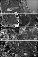
Organic electrode materials are promising and future candidates for applications such as cathode in green lithium-ion batteries (LIBs). Herein, a nanocomposite electrode comprised polyimide nanostructures on few layers exfoliated graphene (PI–FLEG) was developed via a simple in situ polymerization in well dispersed exfoliated graphene sheets. The electrochemical properties of PI–FLEG were significantly increased with the graphene additives and were utilized efficiently when compared with the pure polyimide. When employed as the cathode in LIBs, PI–FLEG can deliver a discharge capacity of 177 mA h g−1 at 0.1C. PI–FLEG retains 80% of its initial discharge capacity after 200 cycles at 0.5C. The significant capacity, good cycling performance and low resistance of PI–FLEG are attributed to the synergistic effects of the vertically grown polyimide on dispersed graphene sheets. This type of electrode may hold an insight for high energy density organic cathodes in rechargeable LIBs.


Introduction

High performance lithium-ion batteries (LIBs) have gained a lot of attention for satisfying the daily demand of electric vehicles, hybrid electric vehicles, smart grids and portable electric devices.1 LIBs are considered promising for renewable energy storage devices due to their high voltage, maximum energy density and reliable electrochemical performance.2–6 The electrode is the core and critical factor and appropriate selection of the active material for electrode preparation is a substantial issue for high performance in LIBs. The cathode materials in LIBs are mostly based on conventional metal oxides, e.g., LiCoO2, LiFePO4 and LiMn2O4.7–9 These inorganic cathode materials have been confirmed as high performance electrode candidates,10,11 but they experience phase transition during the electrochemical performance at ordinary temperature, which offers resistance to the transfer mechanism of Li+ from and into their crystal structure.2 In addition, the limited mineral resources, large energy consumption, high cost and eco-destructive disposal are drawbacks for their applications in various energy storage devices.10,12

Recently, as alternative to inorganic cathode materials, a lot of attention has been given to the preparation of electroactive organic electrode materials.13 Therefore, an essential aspect of sustainable LIBs is to explore renewable electroactive organic electrodes. Such electrodes are believed to be a potential candidate for next generation green LIBs due to their low cost, safety, lightness and environmentally benignness.14 A significant feature of electroactive organics is the conversion mechanism of lithium accumulation from intercalation to chemical bonds via reversible redox reactions.7 Enormous efforts have been made to develop organic cathodes such as using polymer–sulfur nanocomposites,15 polymer radicals,16 conducting polymers17 and organic carbonyls.18 Among these, redox-active organic carbonyls have gained considerable attention as organic cathode materials in rechargeable LIBs. The electrochemical performance of organic carbonyls, e.g., anhydrides and quinines, is based on their redox-active functional groups. These groups provide electron favorable sites accompanied by the lithiation and delithiation of Li+ from and into the organic electrodes during the electrochemical process.19 A polymer with intrinsic redox functional groups and stable skeleton can be applied as a high performance cathode material in stationary and portable electronics because of its fast kinetics compared to conventional cathode materials.7,20 Based on this principle, a type of polymer, polyimide (PI), was introduced. A number of polyimides (PIs) have attracted considerable interest and have proved to be a significant class of polymer.21 PI is an indispensable engineering plastic and is regarded as an intriguing candidate for LIBs due to its high theoretical capacity, mechanical strength and stable cycling performance.22–24 However, the low electrical conductivity of redox organic polymers is a severe obstacle and is a detrimental factor to high energy density electrode materials.25,26

Graphene is a promising material and has recently attracted considerable interest in energy storage fields due to its low-cost, high theoretical surface area (2630 m2 g−1), mechanical stability and high electronic conductivity.5,7,27 As a conductive additive, many authors have reported the significant contribution of graphene with active materials in energy storage materials.28–30 Electrode material–graphene nanocomposites have attracted significant applications in LIBs. The interconnected framework and non-covalent π–π stacking interactions of graphene with polymers provides a large surface area, which makes the process of electrolyte ion insertion/extraction easy and enhances the overall performance of the electrode materials. In the present study, we have synthesized a novel nanocomposite using high quality few layer exfoliated graphene (FLEG) as a conductive additive and PI as the active material via simple in situ polymerization. The pristine FLEG maintains its intact structure due to the mild interactions between FeCl3 (catalyst) and the graphite layers, which provides not only the electronic contribution, but also the ideal skeleton for the vertical growth of PI nanoflakes. FLEG was prepared via an exfoliation method using FeCl3 molecules as the intercalating agent between the adjacent graphite layers.31 High purity and scalable production of graphene via the exfoliation method further guarantees superior performance for lithium-ion storage as opposed to the previously reported chemical reduced graphene oxide (rGO).31,32 The PI nanoflakes were vertically deposited on the surface of the dispersed FLEG sheets. The optimal percentage ratio of FLEG significantly influenced the nanocomposites stability and ensured the remarkable utilization of the active material. The synthesized polymer–graphene nanocomposite shows high performance as a cathode material in LIBs. The synthesis route, structure and electrochemical redox reactions of PI are shown in Scheme 1.


image file: c5ra27471k-s1.tif
Scheme 1 (a) Synthesis of PI, and (b) reversible redox electrochemical mechanism of PI.

Experimental

Pyromellitic dianhydride (PMDA, Sinopharm Chemical Reagent; Co, China) was used after sublimation via vacuum heating at 295 °C. N-Methyl-2-pyrrolidinone solvent (NMP, Xilong Chemical Co; Ltd) was distilled prior to use. Few layer exfoliated graphene (FLEG) and ethylene diamine (EDA, Sinopharm Chemical Reagent; Co, China) was used as received. FLEG (8.01 mg) was first added to 30 mL NMP. The mixture was sonicated for 1 h using a probe sonication machine and was then transferred to a reaction vessel. In a typical process of PI–FLEG synthesis, PMDA monomer (65 mg, 0.01 mmol mL−1) was added to the reaction mixture and stirred until the PMDA was completely dissolved. Subsequently, another monomer, EDA (20 μL, 0.01 mmol mL−1) was added to the reaction mixture. Then, the reaction mixture was refluxed and stirred for 9 h under a flow of inert gas at 150 °C. The molar ratio of the two monomers (PMDA and EDA) was maintained the same. The prepared composite was washed, several times with ethanol and acetone, and then vacuum dried at 80 °C and then heated at 300 °C for 7 h under an inert gas environment. Finally, the as-obtained composite was subjected to Soxhlet extraction with acetone and then vacuum dried at 80 °C overnight. Pure PI was synthesized using the same procedure without adding FLEG.

Characterization

The surface morphology was studied using SEM (HITACHI S-4800) and HRTEM (Tecnai G2F20 U-TWIN). FT-IR spectroscopy was performed using KBr pellets of the samples on a Perkin-Elmer Spectrum-One spectrometer. XRD (Rigaku D/MAX-TTRIII) was examined over a 2θ range from 10° to 70°. The electrical conductivity of the sample films was calculated on a Keithley instrument (Model 4200-SCS) using the four probe method.

Electrochemical measurements

Swagelok type cells comprised the composite cathode; Celgard 2325 membrane and pure Li foil anode were used for the battery tests. To investigate the electrochemical performance of the cathode against a Li anode, the cathode film was prepared using 65 wt% composite, 30 wt% conductive carbon (Printex XE2) and 5 wt% polytetrafluoroethylene (PTFE) binder. The film was further punched into small pieces with a diameter of 11 mm. The electrolyte solution used was 1 M LiN(CF3SO2)2 (LiTFSI) in a mixed solvent of 1,3-dioxolane (DOL) and dimethoxy ethane (DME) (1[thin space (1/6-em)]:[thin space (1/6-em)]1 wt/wt). Aluminum foil (Al, Good fellow) was used as the cathode current collector. All the cells were assembled in an argon-filled glove box. The galvanostatic charge–discharge experiments were tested using an Arbin instruments testing system (Arbin-SCTS) in the potential range from 1.5 to 3.5 V at different current rates. The specific capacity was calculated on the basis of the composite mass. CV was performed at a scan rate of 0.1 mV s−1, whereas electrochemical impedance spectroscopy (EIS) was conducted over the frequency range from 100 kHz to 10 mHz. Both the measurements (CV and EIS) were investigated using a VMP3 electrochemical work station (EG and G, Princeton Applied Research). All the electrochemical experiments were carried out at room temperature.

Results and discussion

The scanning electron microscopy (SEM) and high resolution transmission electron microscopy (HRTEM) results for FLEG are presented in Fig. 1a and b illustrating the soft, thin and multilayer nature of FLEG before polymerization. FLEG was well dispersed in NMP solvent by probe sonication. The well dispersed graphene provides enough surface area, which is highly advantageous for the interface interactions among graphene and the polymer.33 FLEG was polymerized with PMDA to develop a composite (marked as PI–FLEG) via in situ polymerization (Scheme 2). NMP was used as the solvent not only because of its good dispersion of FLEG but also because it is a good solvent for the synthesis of PI.23 In addition this, also avoided the problem of surfactants and small molecules, which is employing for graphene surface modification in many graphene based nanocomposites prepared in aqueous dispersions.34,35 The monomer concentration is one of the most important parameters, which has a significant effect on the electrochemical performance and morphology of the PI nanoflakes. To investigate this effect, different monomer concentrations of PMDA (0.01, 0.05, 0.1 and 0.15 mmol mL−1) were tested. When the concentration of PMDA was 0.01 mmol mL−1, nanoflakes of a larger size (400 nm) were uniformly deposited on the graphene sheets (Fig. 1c). When the concentration was increased to 0.05 and 0.1 mmol mL−1, the PI nanoflakes become thicker and closer to each other (Fig. 1d and e). At a concentration of 0.15 mmol mL−1, the individual nanoflakes disappear and larger aggregates of the PI nanoflakes appear (Fig. 1f).
image file: c5ra27471k-f1.tif
Fig. 1 (a) SEM and (b) HRTEM images of FLEG before polymerization. The PI–FLEG composites prepared with PMDA concentrations of (c) 0.01, (d) 0.05, (e) 0.1 and (f) 0.15 mmol mL−1. (g) and (h) represents SEM images of PI–FLEG based on 5 and 15 wt% FLEG.

image file: c5ra27471k-s2.tif
Scheme 2 Schematic of the synthesis of PI–FLEG via in situ polymerization.

FLEG is another important parameter and provides electron transport channels when properly combined with the polymer matrix. To study the effect of graphene on the electrochemical performance of the composite, nanocomposites with different weight fractions of graphene from 5 to 15 wt% were prepared. It was found that PI–FLEG based on 10 wt% FLEG exhibits excellent electrochemical performance when compared to the nanocomposites consisted of 5 and 15 wt% FLEG. The high performance of 10 wt% PI–FLEG was attributed to the complete utilization of the FLEG surface area available with sufficient electronic contributions. 5 wt% PI–FLEG has a capacity equal to 10 wt% PI–FLEG but the low quantity of FLEG affected its rate performance. PI–FLEG containing 15 wt% graphene has a slightly lower capacitance and moderate rate performance when compared to the above mentioned composites. Fig. 1g and c shows that the composites based on 5 and 10 wt% graphene sheets were uniformly coated by the vertically aligned PI nanoflakes. The PI–FLEG prepared with 15 wt% graphene has some bare graphene nanosheets, which may affect the overall performance of the PI–FLEG (Fig. 1h). The vertically aligned nanoflakes are in direct contact with the electrolyte and therefore contribute to Li+ conduction.

Fourier transform infrared (FT-IR) spectroscopy was performed to confirm the coating of PI on the FLEG (Fig. 2a). The broad peak at 3447 cm−1 was the characteristic absorption peak of OH in the composite. A similar peak was also observed in the pure PI and FLEG spectra. Both pure PI and PI–FLEG exhibit a peak at 1389 cm−1, which was attributed to the stretching vibration of the C–N bond. The absorption peaks around 1781 and 1714 cm−1 were assigned to the asymmetric and symmetric stretching vibration of the C[double bond, length as m-dash]O bonds, respectively. This shows that the carbonyl group was retained in the polymer structure. Before polymerization there was no obvious peak for graphene in the spectrum. After polymerization, all the characteristic peaks of the PI were observed in the composite, which implies the successful loading of PI on the FLEG sheets. The coating of PI nanoflakes on FLEG was further confirmed by X-ray diffraction (XRD). In the XRD patterns of PI–FLEG (Fig. 2b), the two peaks at 2θ = 19.46° and 26.38° were the same as those of pure PI, whereas one peak at 2θ = 26.60° matched with the characteristic peak of FLEG. This result also proves that PI–FLEG possesses a hybrid characteristic of the PI and FLEG sheets. The electrochemical measurements of bare PI, PI with conductive carbon (PI–CC) and PI–FLEG were confirmed using Swagelok type cells. The cathode included 65 wt% active material (PI and PI–FLEG respectively), 30 wt% conductive carbon (CC) and 5 wt% PTFE binder. As aforementioned, the electrochemical performance of PI–FLEG slightly decreased with a high wt% of graphene. This may be attributed to the self-aggregation that occurs among the bare graphene nanosheets, which can influence the performance of the PI–FLEG using the maximum amount of graphene additive.36 Therefore, CC was further used in the electrode fabrication to facilitate the possible utilization of active material. CC and polymer binder integration is an efficient approach in electrode fabrication, which contributes to the electrical conductivity and stability observed during electrochemical applications.37 In addition, both materials do not contribute to the capacity and therefore enhance the overall performance of the electrode.


image file: c5ra27471k-f2.tif
Fig. 2 (a) FT-IR and (b) XRD characterization of FLEG, PI and PI–FLEG.

The electrochemical performance of the PI–FLEG composite was investigated at a current density of 0.1C, 0.5C, 1C, 2C, and 5C (1C = 443 mA g−1). The composite electrode fabricated with 10 wt% CC can deliver an initial discharge capacity of 150 mA h g−1. In contrast, the electrodes fabricated with 20 and 30 wt% CC show an initial discharge capacity of 152 and 177 mA h g−1, respectively. It is worth noting that the PI–FLEG electrodes fabricated with 20 and 30 wt% CC not only exhibit a high capacity but also an improved stability at the different C-rates studied (Fig. S1). These findings reveal that the PI–FLEG electrode fabricated with 30 wt% CC offered outstanding performance; therefore, all the reported results are based on it. Fig. 3a shows that capacity of the PI–FLEG composites decreases with an increase in the monomer concentration. The concentration of monomer (PMDA) was varied from 0.01 mmol mL−1 to 0.15 mmol mL−1. When the concentration of PMDA was 0.01 mmol mL−1, the PI–FLEG shows an excellent rate performance and delivers the highest capacity of 177 mA h g−1 at 0.1C. When the concentration was altered to 0.05 mmol mL−1, the capacity dropped to 167 mA h g−1. At a concentration of 0.1 and 0.15 mmol mL−1, the PI–FLEG capacity was further decreased and delivers an initial discharge capacity of 119 and 90 mA h g−1, respectively. At higher PMDA concentrations, not only the specific capacity of the composites decreases, but also the electrochemical performance was severely affected (Fig. 3b). Based on Fig. 3b, we determined that PI–FLEG comprised 0.01 mmol mL−1 of PMDA has excellent electrochemical activity at all the current densities while PI–FLEG based on high amounts of PMDA shows poor electrochemical performance at higher current density (5C). The continuous fall in the discharge capacities of the composites was attributed to the low electronic conductivity of PI (2.5 × 10⁻⁹ S cm−1) at higher PMDA concentrations, which drastically affects the specific capacity of the composites. At higher PMDA concentrations, the electrochemical performance of the vertically grown PI nanoflakes could not be fully utilized due to the stacking among the adjacent nanoflakes on FLEG. The stacking phenomenon was ascribed to the thickness of the individual nanoflakes, which reduces the distance between the PI nanoflakes. Moreover, the channels among the PI nanoflakes disappear at higher concentrations (Fig. 1c–f). At lower PMDA concentrations (0.01 mmol mL−1), these channels contribute to the infiltration of Li+ during the electrochemical performance, which leads to an enhanced overall performance of the cathode materials. Therefore, a 0.01 mmol mL−1 concentration was optimized and fixed for the experiments. To compare the capacity, values calculated at 0.1C are preferred to facilitate the comparison. Fig. 3c confirms the rate performance of PI–FLEG based on the different weight percentage of FLEG. The PI–FLEG comprised 5 and 10 wt% FLEG that delivers a discharge capacity of 177 mA h g−1. After adding 15 wt% FLEG, the discharge capacity of PI–FLEG decreases to 165 mA h g−1. This is because at higher weight percentage of FLEG sheets remain unoccupied (Fig. 1h), which may effect the total performance of the PI–FLEG. Graphene provides non-equivalent geometric and electronic sites and therefore the homogenous distribution of graphene and the polymers is the main factor that can change the properties of graphene–polymer composites.33,38 In addition to the transportation of Li+, the well aligned PI nanoflakes with FLEG also helps in avoiding the aggregation phenomenon observed among the graphene sheets, which create the basis to enhance the performance of the PI–FLEG. Based on Fig. 3c, we conclude that 10 wt% PI–FLEG not only shows a high reversible specific capacity, but also an excellent rate performance for organic cathode materials. In contrast, the 5 and 15 wt% PI–FLEG nanocomposites show poor rate performance. Moreover, to identify the capacity contribution from FLEG as a cathode material, the electrochemical performance of the FLEG was also deliberated (Fig. S2). FLEG itself delivers an initial discharge capacity of 27 mA h g−1 at 0.1C between the potential windows from 3 V to 3.5 V, which was consistent with the previous studies.7,30 Thus, for 10 wt% PI–FLEG, FLEG itself contributed capacity of 2.7 mA h g−1 among the total discharge capacity of PI–FLEG. The optimized conditions (0.01 mmol PMDA and 10 wt% FLEG) were discovered and used to investigate the electrochemical performance of the as-prepared PI–FLEG. Fig. 3d shows the characteristic charge and discharge curves of PI–FLEG. The average discharge plateau potential was 2.08 V, whereas the charge potential was 2.18 V. The shape of the charge–discharge curves remains unchanged at the different current rates. Furthermore, the two discharge plateaus at each current density correspond to a two-step, 2e redox reaction of the carbonyl groups, which is in accordance with the CV results. At 0.1C, a discharge capacity of 177 mA h g−1 was obtained, whereas at 1C and 2C, 134 and 116 mA h g−1 discharge capacity was achieved with no severe polarization. PI has a theoretical capacity of 443 mA h g−1 based on a four-electron redox process. In a practical charge–discharge process, only two electrons can be transferred reversibly (Scheme 1) and therefore about half of the theoretical capacity (221 mA h g−1) can be obtained. Fig. 4a confirms a comparative rate performance of the PI–CC and PI–FLEG. At each current density, 5 cycles were tested with a constant charge–current density. PI–CC shows a discharge capacity of 164 mA h g−1 at 0.1C. In contrast, PI–FLEG delivers a discharge capacity of 177 mA h g−1 under the same conditions.


image file: c5ra27471k-f3.tif
Fig. 3 (a) The effect of PMDA on the capacity of PI–FLEG. (b) The effect of PMDA concentration on the rate performance of PI–FLEG. (c) The rate performance of PI–FLEG based on different wt% of FLEG. (d) The galvanostatic charge–discharge profiles at different C-rates.

image file: c5ra27471k-f4.tif
Fig. 4 (a) The comparative rate performance of PI–CC and PI–FLEG at different C-rates. (b) The CV curves for PI–CC and PI–FLEG at a scan rate of 0.1 mV s−1. (c) Electrochemical impedance spectroscopy of PI–CC and PI–FLEG with insight equivalent circuits. (d) The cycling performance of PI–FLEG for 200 cycles at a current speed of 0.5C.

In addition to the specific capacity, the rate performance of PI–FLEG was also enhanced significantly. At 2C and 5C, PI–FLEG retains 116 and 38 mA h g−1 discharge capacity of that at 0.1C. In contrast, at 2C, PI–CC maintains capacity of 12 mA h g−1, while it does not show any electrochemical activity at 5C. For PI–FLEG, a reversible capacity of 149 mA h g−1 was achieved when the current density was decreased to 0.1C. We also conducted an experiment to investigate the electrochemical performance of bare PI (PI without conductive carbon and FLEG). It was found that the bare PI can only delivers a discharge capacity of 3.2 mA h g−1 at 0.1C, whereas it showed very poor performance at higher C-rates (Fig. S3). The low discharge capacity and poor rate performance of the bare PI was attributed to its extremely low conductivity (2.5 × 10⁻⁹ S cm−1). The above mentioned results confirm that the performance of bare PI was greatly enhanced by the hybrid materials (PI–FLEG). These discoveries suggests that FLEG significantly contributed in the stability of the composite electrode and thus offered the excellent discharge rate capability of PI–FLEG (Fig. 4a). The high rate performance was assigned to the interactions among the vertically aligned PI nanoflakes and FLEG sheets.

Cyclic voltammetry (CV) was conducted to confirm the insertion/extraction mechanism of Li+ associated with PI–CC and PI–FLEG (Fig. 4b). The PI–CC and PI–FLEG curves show two pairs of redox peaks; two reduction peaks of PI–FLEG positioned at 1.91 and 2.17 V and the oxidation peaks located at 2.20 and 2.46 V. PI–CC and PI–FLEG show similar CV patterns, but PI–FLEG has strong peak positions, which shows that PI–FLEG has a larger electronic conductivity and electrochemically active species. The CV profiles indicate that the redox processes are completed in two continuous steps. First, in the reduction process, each formula unit was converted into the radical anion and then to the dianion, associated with the addition of Li+. Second, in the oxidation process, Li+ was detached from the lithium enolate and the carbonyl groups are reconstructed (Scheme 1b). The electrical conductivity of the FLEG, PI–CC and PI–FLEG films was calculated using a four-probe measurement technique. The compositions of the film electrodes remain the same as used in the electrochemical measurements. FLEG is an extremely light weight material and has an electronic conductivity of 3.99 × 10² S cm−1, whereas the electrical conductivities of PI–CC and PI–FLEG are 3.50 × 10⁻¹ and 1.94 S cm−1, respectively. The high electrochemical performance of PI–FLEG was attributed to the additional electron transport channels provided by FLEG. This confirms an obvious difference in the electronic conductivities of the electrodes. Electrochemical impedance spectroscopy (EIS) was carried out to test the resistance of PI–CC and PI–FLEG in the form of Nyquist plots (Fig. 4c). The electrodes resistance was explained in term of the charge-transfer resistance (Rct), which was 133 Ω for PI–CC and 78 Ω for PI–FLEG. These results are comparable to the conductivity tests, which prove the smaller resistance to the transportation of Li+ in PI–FLEG than that found with PI–CC. The significant electronic conductivity and small resistance of PI–FLEG results in its high performance in LIBs. The cycling performance of PI–FLEG was tested to determine its consistency, which is essential for the real application of electrode materials in LIBs. At a current speed of 0.5C, the PI–FLEG electrodes were tested for 200 cycles (Fig. 4d). In the first cycle, the tested electrode delivered an initial discharge capacity of 135 mA h g−1, whereas in the last cycle the maintained capacity was 108 mA h g−1. After the cycling test, 80% of the initial discharge capacity was retained with a coulombic efficiency near to 100%. These findings reveal the practical applicability of our system in LIBs.

Conclusions

In summary, we have developed a novel PI–FLEG nanocomposite that can be used as a high performance cathode in rechargeable lithium ion batteries.

PI–FLEG was prepared via a simple in situ polymerization technique in NMP. The NMP solvent has a significant role in the synthesis of PI and the dispersion of FLEG. The interconnected framework and vertically aligned growth of the PI nanoflakes were attributed to the pristine structure of FLEG. In addition, FLEG contributed to the electronic conductivity of the PI–FLEG, which enhanced the performance of the cathode material. The wt% contribution of FLEG was optimized to obtain a high performance electrode. The morphology of the PI nanoflakes was controlled by the PMDA concentrations, which further optimized the electrode performance. PI nanoflakes shorten the diffusion path length among the electrolyte and electrode interfaces, which leads to a further increase in the rate of lithiation/delithiation. The channels between the PI nanoflakes have a significant role towards the infiltration of the electrolyte. Moreover, high PMDA amounts significantly influence the capacity and rate performance of PI–FLEG at various current densities. Based on the electrode weights of PI and PI–FLEG, at a current density of 0.1C a discharge capacity of 164 (for PI–CC) and 177 mA h g−1 were delivered. This finding proves that most of the theoretical capacity of PI was successfully utilized in PI–FLEG. The synthetic route of the composite cathode was simple and shows remarkable battery performance. The present study provides an alternative strategy for enhancing the battery performance of other polymer cathodes.

Acknowledgements

This study is supported by the Beijing Municipal Science and Technology Commission (No. Z141100003814010), the National Natural Science Foundation of China (Grant No. 21125420, 51473039), and CAS-TWAS President's PhD Fellowship program.

References

  1. J.-M. Kim, H.-S. Park, J.-H. Park, T.-H. Kim, H.-K. Song and S.-Y. Lee, ACS Appl. Mater. Interfaces, 2014, 6, 12789–12797 CAS.
  2. Y. Meng, H. Wu, Y. Zhang and Z. Wei, J. Mater. Chem. A, 2014, 2, 10842–10846 CAS.
  3. Z. Song and H. Zhou, Energy Environ. Sci., 2013, 6, 2280–2301 CAS.
  4. F. Cheng, J. Liang, Z. Tao and J. Chen, Adv. Mater., 2011, 23, 1695–1715 CrossRef CAS PubMed.
  5. G. Zhou, F. Li and H.-M. Cheng, Energy Environ. Sci., 2014, 7, 1307–1338 CAS.
  6. M. E. Bhosale and K. Krishnamoorthy, Chem. Mater., 2015, 27, 2121–2126 CrossRef CAS.
  7. Z. Song, T. Xu, M. L. Gordin, Y.-B. Jiang, I.-T. Bae, Q. Xiao, H. Zhan, J. Liu and D. Wang, Nano Lett., 2012, 12, 2205–2211 CrossRef CAS PubMed.
  8. W. Guo, Y.-X. Yin, S. Xin, Y.-G. Guo and L.-J. Wan, Energy Environ. Sci., 2012, 5, 5221–5225 CAS.
  9. J. W. Fergus, J. Power Sources, 2010, 195, 939–954 CrossRef CAS.
  10. A. Manthiram, J. Phys. Chem. Lett., 2011, 2, 176–184 CrossRef CAS.
  11. P. Sharma, D. Damien, K. Nagarajan, M. M. Shaijumon and M. Hariharan, J. Phys. Chem. Lett., 2013, 4, 3192–3197 CrossRef CAS.
  12. H. P. Wu, K. Wang, Y. N. Meng, K. Lu and Z. X. Wei, J. Mater. Chem. A, 2013, 1, 6366–6372 CAS.
  13. B. Genorio, K. Pirnat, R. Cerc-Korosec, R. Dominko and M. Gaberscek, Angew. Chem., Int. Ed., 2010, 49, 7222–7224 CrossRef CAS PubMed.
  14. Y. F. Shen, D. D. Yuan, X. P. Ai, H. X. Yang and M. Zhou, J. Polym. Sci., Part B: Polym. Phys., 2015, 53, 235–238 CrossRef CAS.
  15. Y. X. Yin, S. Xin, Y. G. Guo and L. J. Wan, Angew. Chem., Int. Ed., 2013, 52, 13186–13200 CrossRef CAS PubMed.
  16. K. Oyaizu and H. Nishide, Adv. Mater., 2009, 21, 2339–2344 CrossRef CAS.
  17. M. E. Abdelhamid, A. P. O'Mullane and G. A. Snook, RSC Adv., 2015, 5, 11611–11626 RSC.
  18. H. Wu, S. A. Shevlin, Q. Meng, W. Guo, Y. Meng, K. Lu, Z. Wei and Z. Guo, Adv. Mater., 2014, 26, 3338–3343 CrossRef CAS PubMed.
  19. W. W. Huang, Z. Q. Zhu, L. J. Wang, S. W. Wang, H. Li, Z. L. Tao, J. F. Shi, L. H. Guan and J. Chen, Angew. Chem., Int. Ed., 2013, 52, 9162–9166 CrossRef CAS PubMed.
  20. D. Chen, A.-J. Avestro, Z. Chen, J. Sun, S. Wang, M. Xiao, Z. Erno, M. M. Algaradah, M. S. Nassar, K. Amine, Y. Meng and J. F. Stoddart, Adv. Mater., 2015, 27, 2907–2912 CrossRef CAS PubMed.
  21. A. Ghosh, S. K. Sen, S. Banerjee and B. Voit, RSC Adv., 2012, 2, 5900–5926 RSC.
  22. J.-H. Park, J.-M. Kim, J.-S. Kim, E.-G. Shim and S.-Y. Lee, J. Mater. Chem. A, 2013, 1, 12441–12447 CAS.
  23. Z. P. Song, H. Zhan and Y. H. Zhou, Angew. Chem., Int. Ed., 2010, 49, 8444–8448 CrossRef CAS PubMed.
  24. B. Häupler, A. Wild and U. S. Schubert, Adv. Energy Mater., 2015, 5, 1402034 Search PubMed.
  25. Y. Liang, P. Zhang, S. Yang, Z. Tao and J. Chen, Adv. Energy Mater., 2013, 3, 600–605 CrossRef CAS.
  26. M. Lee, J. Hong, H. Kim, H.-D. Lim, S. B. Cho, K. Kang and C. B. Park, Adv. Mater., 2014, 26, 2558–2565 CrossRef CAS PubMed.
  27. Z. S. Wu, G. M. Zhou, L. C. Yin, W. Ren, F. Li and H. M. Cheng, Nano Energy, 2012, 1, 107–131 CrossRef CAS.
  28. X. F. Zhou, F. Wang, Y. M. Zhu and Z. P. Liu, J. Mater. Chem., 2011, 21, 3353–3358 RSC.
  29. S. M. Paek, E. Yoo and I. Honma, Nano Lett., 2009, 9, 72–75 CrossRef CAS PubMed.
  30. D. H. Wang, D. W. Choi, J. Li, Z. G. Yang, Z. M. Nie, R. Kou, D. H. Hu, C. M. Wang, L. V. Saraf, J. G. Zhang, I. A. Aksay and J. Liu, ACS Nano, 2009, 3, 907–914 CrossRef CAS PubMed.
  31. X. M. Geng, Y. F. Guo, D. F. Li, W. W. Li, C. Zhu, X. F. Wei, M. L. Chen, S. Gao, S. Q. Qiu, Y. P. Gong, L. Q. Wu, M. S. Long, M. T. Sun, G. B. Pan and L. W. Liu, Sci. Rep., 2013, 3, 1134 Search PubMed.
  32. D. Y. Pan, S. Wang, B. Zhao, M. H. Wu, H. J. Zhang, Y. Wang and Z. Jiao, Chem. Mater., 2009, 21, 3136–3142 CrossRef CAS.
  33. X. Sun, H. Sun, H. Li and H. Peng, Adv. Mater., 2013, 25, 5153–5176 CrossRef CAS PubMed.
  34. D. H. Wang, R. Kou, D. Choi, Z. G. Yang, Z. M. Nie, J. Li, L. V. Saraf, D. H. Hu, J. G. Zhang, G. L. Graff, J. Liu, M. A. Pope and I. A. Aksay, ACS Nano, 2010, 4, 1587–1595 CrossRef CAS PubMed.
  35. H. X. Chang and H. K. Wu, Energy Environ. Sci., 2013, 6, 3483–3507 CAS.
  36. X. Huang, X. Qi, F. Boey and H. Zhang, Chem. Soc. Rev., 2012, 41, 666–686 RSC.
  37. Z. Liu, A. Yu and J. Y. Lee, J. Power Sources, 1998, 74, 228–233 CrossRef CAS.
  38. R. Raccichini, A. Varzi, S. Passerini and B. Scrosati, Nat. Mater., 2015, 14, 271–279 CrossRef CAS PubMed.

Footnote

Electronic supplementary information (ESI) available: Rate performance of PI–FLEG with variation of conductive carbon, rate performance of FLEG and bare PI. See DOI: 10.1039/c5ra27471k

This journal is © The Royal Society of Chemistry 2016
Click here to see how this site uses Cookies. View our privacy policy here.