Three-dimensional light confinement in a PT-symmetric nanocavity

Wenzhao Sun a, Zhiyuan Gua, Shumin Xiao*b and Qinghai Song*a
aIntegrated Nanoscience Lab, Department of Electrical and Information Engineering, Harbin Institute of Technology, Shenzhen, China. E-mail: qinghai.song@hitsz.edu.cn; Fax: +86 755 2603 2022; Tel: +86 755 2661 2207
bIntegrated Nanoscience Lab, Department of Electrical and Information Engineering, Harbin Institute of Technology, Shenzhen, China. E-mail: shumin.xiao@hitsz.edu.cn

Received 21st December 2015 , Accepted 29th December 2015

First published on 6th January 2016


Abstract

Light confinement and manipulation in nanoscale have gained intense research attention due to their potential applications ranging from cavity quantum electrodynamics to nano-networks. Within all this research, the effective mode volume (Veff) is the key parameter that determines light–matter interaction. While various nano-cavities have been developed in past decades, very few have successfully confined light within the nanoscale in all three dimensions. Here we demonstrate a robust mechanism that can improve light confinement in nanostructures. By breaking the parity–time (PT) symmetry in nanowire based nanocavities, we find that the resonant modes are mostly localized at the interfaces between gain and loss regions, providing an additional way to confine light along a third direction. Taking a hybrid plasmonic Fabry–Perot cavity as an example, we show that the Veff has been dramatically improved from ∼0.0092 μm3 to ∼0.00169 μm3 after the breaking of PT symmetry. In addition to the perfect PT symmetric cavities with (n(r) = n(−r)*), we have also observed similar three-dimensional light confinements and an ultrasmall Veff in quasi-PT symmetric systems with fixed losses. We believe that our finding will significantly improve light–matter interaction in nanostructures and help the advance of their applications.

The rapid developments in nano-networks and nano-devices have triggered intense research attention for nanoscale coherent light sources.1–3 In the past decade, the sizes of lasers have been quickly reduced from microscale to subwavelength and eventually to nanoscale.4–6 Several schemes have been utilized to generate nanosized light confinements, e.g., a photonic crystal nanocavity,1 nanorods and nanowires,6 and plasmonic nanocavities.4 Spaser, which was pioneered by Bergman and Stockman,7 is a prominent example. By replacing the photon and resonances with a surface plasmon and plasmonic mode, spasers have been successfully observed in a 44 nm-diameter gold-dyed silica core–shell nanoparticle.8 To date, spasers have been demonstrated in many systems including, nanoantenna,9 nanoparticle arrays,10 and hybrid plasmonic waveguides.11 Compared with the other spasers or nanolasers, the hybrid plasmonic nanolasers are extremely interesting because they combine the advantages of single crystalline nanowires and surface plasmon polaritons, and they have the potentials to be compatible with conventional CMOS technology.

Soon after the first experimental demonstration,11 hybrid plasmonic lasers have been reported in GaN,12 CdS,13 GaAs,14 and ZnO15 based nano-systems and the Veff has been dramatically reduced. While the hybrid plasmonic systems can give an extremely small effective mode area (on the order of nm2), the values of Veff are limited by the lengths of nanowires or waveguides. In this sense, hybrid plasmonic waveguides are only nice platforms for two-dimensional light confinement. In the third direction, they mainly function as conventional Fabry–Perot cavities. Although periodic structures such as photonic crystals have been utilized to improve the light confinement in the third direction,16 the designs are usually too complicated for practical applications. Therefore, it is highly desirable to find a simple way to confine light in full three dimensions. Here we explore one possibility by combining the surface mode and two-dimensional light confinement in a hybrid plasmonic waveguide. By breaking the parity–time (PT) symmetry in nanolasers, surface modes have been generated at the gain–loss interface. Consequently, a full three-dimensional light confinement has been formed and the Veff has been greatly reduced.

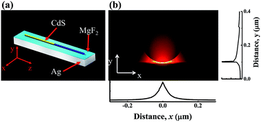
Our finding is based on the recently developed PT symmetry in a non-Hermitian system.17 Due to the generality of gain and loss in optical systems, PT symmetry has been widely studied in the past few years.18–20,22–25 A number of unique properties such as being perfect absorbers,19 non-reciprocity,20 unidirectional invisibility,21 and single mode microlasers22–25 have been designed and experimentally realized. Here we study the PT symmetry within hybrid plasmonic nanolasers. Fig. 1(a) depicts a schematic picture of the designed structure. A CdS nanowire with radius R = 100 nm and length L = 10 μm is placed onto MgF2 coated Ag films. The thickness of MgF2 and Ag films are fixed at 5 nm and 100 nm, respectively. This is one of the typical structures of a hybrid plasmonic nanocavity. It can also switch to a metal-coated Si waveguide for the top-down fabrication process. In general, plasmonic nanolasers can be generated by pumping the nanowire entirely. Such nanolasers are well confined within the gap region (see Fig. 1(b)).26 From the transverse field distributions, it is easy to see that the lights are confined within tens of nanometers in both x and y directions.


image file: c5ra27384f-f1.tif
Fig. 1 Schematic picture of the designed nanocavity and the field confinement (a). A CdS nanowire with radius R is placed onto a MgF2 coated Ag film. The gain and loss are applied in the yellow and blue regions of the CdS nanowire. (b) The mode profile in the transverse plane.

The situation changes when the gain and loss are introduced to the CdS nanowire. As depicted in Fig. 1(a), the nanowire is subdivided from the center and then the gain and loss are applied to the left (yellow) and right (blue) regions in Fig. 1(a). Here the gain and loss are defined with a refractive index as nL = n0 + n′′1i, and nR = n0 + n′′2i. For the CdS nanowire, n0 is fixed at 2.55 and the imaginary parts are set as n′′1 = −n′′2 to form the PT symmetry. For the case of a passive cavity (n′′1 = n′′2 = 0), the resonant modes travel individually and do not cross-talk. Meanwhile the situation is different when the PT-symmetric configuration is applied to the cavity. The two initial resonant modes at resonance frequencies ωa and ωb with an adjacent mode number supported by the F–P nanocavity have the possibility to couple one another. With an increase of the gain and loss, the amplitudes of the two resonances are strongly modified and redistribute. Thus the resonance behaviors of the non-Hermitian system depicted in Fig. 1(a) can be predicted by the coupled-mode theory via the following equations:27

 
image file: c5ra27384f-t1.tif(1)
 
image file: c5ra27384f-t2.tif(2)
where a and b are their respective modal amplitudes, γa,b are their associated gain and loss rates, κ is the intrinsic loss of the metal, and J is the real-value coupling constant. By considering the perfect PT symmetry with ωa + ωb = 2ωn, and γa = −γb = γn, the eigenfrequencies can be written as:
 
image file: c5ra27384f-t3.tif(3)

Fig. 2(a) and (b) show the resonant behaviors with perfect PT symmetry with γa = −γb. When the gain factor γa is small, the real parts of two resonances slightly approach one another and the imaginary parts are kept as a constant at κ. Once γa is larger than the coupling constant J, the real part of frequencies merge to ωn, whereas the imaginary parts quickly bifurcate.19,28 One mode becomes more lossy. The other mode reaches the threshold (Im(E) = 0) and becomes a lasing mode. At the point γa = J, both the real parts and imaginary parts of the two resonances are the same, clearly showing the well-known exceptional point.


image file: c5ra27384f-f2.tif
Fig. 2 PT symmetry and quasi-PT symmetry. (a) and (b) are the real and imaginary parts of the eigenfrequencies (E) as a function of γa under perfect PT symmetry. (c) and (d) are similar to (a) and (b) except γb = −0.05. The other parameters are κ = 0.05 and J = 0.06.

In additional to the perfect PT symmetric system, we have also studied the systems with a fixed loss. Compared with perfect PT symmetric systems, this setting is more practical in experiments. This is because the gain is much easier to tune than the loss. It can be simply realized by selectively pumping.29 But the increase in loss usually relies on a complicated carrier injection or bias voltage. In quasi-PT symmetric systems, the eigenfrequencies E of eqn (1) and (2) can be expressed as:

 
image file: c5ra27384f-t4.tif(4)
where Δω = ωaωb is the detuned condition. Then the resonant behaviors can also be predicted from eqn (4). The calculated results are shown in Fig. 2(c) and (d). We can see that the basic behaviors are similar to the case of the perfect PT symmetric system. With the increase of γa, the real parts of the eigenfrequencies gradually approach and merge. And their imaginary parts bifurcate after the PT symmetry breaking. The only difference is that the imaginary parts of the two modes increase simultaneously before the exceptional point and then bifurcate.27

Based on the above theoretical analysis, we numerically studied the structure using a commercial finite element method package (COMSOL multiphysics 4.3a). The dielectric constant of MgF2 is 1.9 and the dispersion of Ag is defined with the Drude model. Perfectly matched layers have been used to absorb the outgoing waves. Thus the resonances inside the hybrid plasmonic structure are quasi-bound modes with complex eigenfrequencies (f). The real part of the frequency (Re(f)) corresponds to the resonant wavelength and the imaginary part relates to the loss (or gain). By changing n′′1 (or −n′′2), we have studied the real parts and imaginary parts of the eigenfrequencies. All the results are summarized in Fig. 3(a) and (b). When n′′1 = −n′′2 = 0, the cavity is a conventional hybrid plasmonic nanocavity. Thus a series of hybrid plasmonic modes have been observed. The field distribution in the transverse plane (xy plane) is similar to Fig. 1(b). The mode profiles in the z direction consist of periodic nodes and the maximal values within every two nodes are quite similar (see examples in the top panel of Fig. 3(c)). Thus it is easy to know that these resonances are Fabry–Perot modes with mode numbers m = 68–71.


image file: c5ra27384f-f3.tif
Fig. 3 PT symmetry breaking in a hybrid plasmonic nanocavity. (a) and (b) are the dependencies of the resonant frequency (Re(f)) and the β (Im(f/100c)) value on n′′1. (c) The field patterns along the xz plane within the MgF2 gap with n′′1 = 0 (top) and n′′1 = 0.06 (bottom). (d) The Veff as a function of n′′1.

With the increase of gain (n′′1 or −n′′2), the real and imaginary parts of eigenfrequencies show quite different behaviors from conventional plasmonic nanolasers. As shown in Fig. 3(a), the real parts of the frequencies change slightly at the beginning. Once n′′1 is larger than 0.04, two resonant modes approach each other quickly and merge. Meanwhile, the imaginary parts keep as constants and finally bifurcate. All of these behaviors are very similar to the theoretical model in Fig. 2(a) and (b), clearly demonstrating the broken PT symmetry in our hybrid plasmonic nanocavity.

As the resonant frequencies of two nearby modes merge to the same frequencies, the mode spacing of final lasing modes are thus doubled after the PT symmetry breaking.29,30 This is one difference between PT symmetric Fabry–Perot lasers and microdisk lasers. In the latter case, the modes with the same Azimuthal numbers couple to each other. Compared with the doubled mode spacing, the field profiles of lasing and absorption modes are more interesting. In conventional PT symmetric lasers, the lasing and absorption modes are simply considered to be localized within gain and loss regions. In our hybrid plasmonic nanocavity, the mode profiles are more complicated.30

In the Fabry–Perot cavity, the mode at resonance ω can be expressed as:

 
image file: c5ra27384f-t5.tif(5)
where ψ(x) is the field distribution, ni = nL, nR at left and right regions, and c is the speed of light in a vacuum. Then the mode profile within the gain region can be written as:
 
ψ(x) = a+einLkx + ae−inLk(xL/2). (6)
Here k is ω/c, a+ and a are the amplitudes of the forward and backward propagating waves, respectively.30 At the lasing threshold, the usual round trip phase and amplitude condition for the FP cavity is r1r2[thin space (1/6-em)]exp(inLL) = 1, where r1 and r2 are the reflectivity at the left end-facet and gain–loss interface. Then the ratio between the forward and backward propagating waves is:
 
image file: c5ra27384f-t6.tif(7)

In the case of the hybrid plasmonic waveguide,11 the effective refractive indices of the plasmonic mode in gain and loss regions are 2.3 + 0.047068i and 2.3 − 0.052053i, respectively. We can see that the refractive index difference between the hybrid waveguide and air is much larger than the one between the gain and loss regions. Following the Fresnel equations, it is easy to get a result of r1r2. Consequently, the lasing mode in the gain region is dominated by the right-propagating waves. From eqn (6), we know that the electric field is amplified before it reaches the gain–loss interface. Then the amplitude of the electric field reaches a maximum at the gain–loss interface. Following eqn (6) and (7), a similar phenomenon holds true for the absorption mode. Thus both of them can be considered as surface modes after PT symmetry breaking.

Such kinds of surface modes have been observed from our numerical calculations. As shown in the bottom panel of Fig. 3(c), we can see that the electric fields of both the lasing mode and absorption modes are mainly confined around the gain–loss interface. The intensity of the resonant mode increases exponentially from left end-facet to the gain–loss interface and then reduces exponentially. Taking account of the two-dimensional mode confinement (Fig. 1(b)), we thus know that full three-dimensional light confinement has been obtained by applying PT symmetry. This kind of thee-dimensional light confinement is important for Veff. Following the definition of the effective mode volume (∭W(r)d3r/max(W(r))), it is easy to know that Veff is inversely proportional to the maxima value of the field. Therefore, the Veff in PT symmetric nanocavities can be further improved. The results are plotted in Fig. 3(d). With the increase of n′′1, Veff reduces very quickly. When n′′1 is larger than 0.06, Veff is leveling out at around 0.00169 μm3, which is much smaller than the one of the conventional hybrid plasmonic mode. Therefore, applying PT symmetry to hybrid plasmonic nanolasers can effectively improve the effective mode volume and the corresponding light matter interaction within nanocavities.

As shown in Fig. 2(c) and (d), similar PT-symmetric phenomena can also be observed in systems with fixed loss. Thus it is also interesting to explore the behaviors in quasi-PT symmetric systems. One example is depicted in Fig. 4. Similar to Fig. 3, four Fabry–Perot modes with m = 68–71 have been considered. With an increase of n′′1, their real parts also slightly approach each other and merge quickly at n′′1 ∼ 0.06. At the same time, the imaginary parts of all the resonances approach zero first and then bifurcate. One resonance of each mode pair turns out to be the lasing mode and the other one transits to the lossy mode simultaneously. Fig. 4(c) illustrates the corresponding field distributions at n′′1 = 0 (top panel) and n′′1 = 0.06 (bottom panel), respectively. After the breaking of PT symmetry, we can see that both the lasing mode and absorption mode are confined well at the gain–loss interfaces. Consequently, the effective mode volume can also been significantly improved (see Fig. 4(d)). It’s also worth noting that the refractive index of the active medium (CdS in our case) will be modified when the gain is applied to the CdS nanowire in our model. Thus it is essential to investigate the robustness of the PT-symmetric behaviors with modal dispersion induced by CdS. We calculated the PT-symmetry breaking phase when the real part of the refractive index of CdS changes from 2.5 at n′′1 = 0 to 2.56 at n′′1 = 0.1. The PT-symmetry breaking and mode bifurcation still occur at n′′1 = 0.06, clearly demonstrating the robust phenomenon of modal localization in the case of the PT-symmetric system with material dispersion.


image file: c5ra27384f-f4.tif
Fig. 4 Quasi-PT symmetry breaking in a hybrid plasmonic nanocavity. The same as Fig. 3 except n′′2 is fixed at −0.05.

In conclusion, we have studied the light confinements within a hybrid plasmonic nanocavity with PT symmetry. In additional to the two-dimensional light confinement in the transverse plane, the light is mostly localized around the gain–loss interface along the third dimension by breaking PT symmetry or quasi-PT symmetry. Such kinds of surface modes have provided a way to improve the light confinement in all three dimensions. Consequently, the Veff after PT symmetry breaking can be as small as 0.00169 μm3, which is much smaller than a conventional hybrid plasmonic nanocavity. We note that Veff can be further improved if the periodic structures and PT symmetry are applied simultaneously onto the hybrid plasmonic nanolasers. We believe that our research will be interesting for the study of light–matter interaction in nanocavities.

Method

Numerical settings

In this letter, the finite element method (FEM, Comsol Multiphysics 4.3a) is employed to calculate the eigenfrequency of the resonant modes in the hybrid plasmonic nanocavity. The 3D eigenfrequency study from the radio frequency module is utilized to search the eigenvalues of the cavity. The complex refractive index is n = n + ik with k > 0 for the gain and k < 0 for the loss. The simulation region is terminated using the Perfectly Matched Layer (PML) and scattering boundary condition to absorb the scattering energy. An eigenvalue solver is used to find the complex resonance frequency f = freal + ifimag. The effective mode volume can be expressed as:
 
image file: c5ra27384f-t7.tif(8)
where W(r) is the energy density of the cavity and takes the form:
 
image file: c5ra27384f-t8.tif(9)

Acknowledgements

This work is supported by NSFC11204055, NSFC61222507, NSFC11374078, NCET-11-0809, KQCX2012080709143322, KQCX20130627094615410, JCYJ20140417172417110, and JCYJ20140417172417096.

References

  1. Y. Akahane, T. Asano and B. S. Song, Nature, 2003, 425, 6961 CrossRef PubMed.
  2. A. Shacham, K. Bergman and L. P. Carloni, IEEE Trans. Comput., 2008, 57, 1246 CrossRef.
  3. R. M. Ma, et al., Nanotechnology, 2007, 18, 205605 CrossRef.
  4. W. L. Barnes, A. Dereux and T. W. Ebbesen, Nature, 2003, 424, 824 CrossRef CAS PubMed.
  5. Q. H. Song, H. Cao, S. T. Ho and G. S. Solomon, Appl. Phys. Lett., 2009, 94, 061109 CrossRef.
  6. M. H. Huang, et al., Science, 2001, 292, 1897 CrossRef CAS PubMed.
  7. D. J. Bergman and M. I. Stockman, Phys. Rev. Lett., 2003, 90, 027402 CrossRef PubMed.
  8. M. A. Noginov, et al., Nature, 2003, 460, 7259 Search PubMed.
  9. W. Zhou, et al., Nat. Nanotechnol., 2013, 8, 506 CrossRef CAS PubMed.
  10. C. Zhang, et al., Nano Lett., 2015, 15, 1382 CrossRef CAS PubMed.
  11. R. F. Oulton, et al., Nature, 2009, 461, 629 CrossRef CAS PubMed.
  12. C. Y. Wu, et al., Nano Lett., 2011, 11, 4256 CrossRef CAS PubMed.
  13. R. M. Ma, R. F. Oulton, V. J. Sorger, G. Bartal and X. Zhang, Nat. Mater., 2011, 10, 110 CrossRef CAS PubMed.
  14. J. Li, et al., Nanoscale, 2013, 5, 8494 RSC.
  15. T. P. H. Sidiropoulos, et al., Nat. Phys., 2014, 10, 870 CrossRef CAS.
  16. J. T. Robinson, C. Manolatou, L. Chen and M. Lipson, Phys. Rev. Lett., 2005, 95, 143901 CrossRef PubMed.
  17. C. M. Bender and S. Boettcher, Phys. Rev. Lett., 1998, 80, 5243 CrossRef CAS.
  18. C. E. Rüter, K. G. Makris, R. El-Ganainy, D. N. Christodoulides, M. Segev and D. Kip, Nat. Phys., 2010, 6, 192 CrossRef.
  19. Y. D. Chong, L. Ge and A. D. Stone, Phys. Rev. Lett., 2011, 106, 093902 CrossRef CAS PubMed.
  20. B. Peng, et al., Nat. Phys., 2014, 10, 394 CrossRef CAS.
  21. Z. Lin, H. Ramezani, T. Eichelkraut, T. Kottos, H. Cao and D. N. Christodoulides, Phys. Rev. Lett., 2011, 106, 213901 CrossRef PubMed.
  22. L. Feng, Z. J. Wong, R. M. Ma, Y. Wang and X. Zhang, Science, 2014, 346, 972 CrossRef CAS PubMed.
  23. H. Hodaei, M. A. Miri, M. Heinrich, D. N. Christodoulides and M. Khajavikhan, Science, 2014, 346, 975 CrossRef CAS PubMed.
  24. Q. H. Song, J. K. Li, W. Z. Sun, N. Zhang, S. Liu, M. Li and S. M. Xiao, Opt. Express, 2015, 23, 24257 CrossRef PubMed.
  25. L. G. E. Ge and A. D. Stone, Phys. Rev. Lett., 2014, 4, 031011 Search PubMed.
  26. Z. Y. Gu, et al., Sci. Rep., 2015, 5, 9171 CrossRef.
  27. R. EI-Ganainy, M. Khajavikhan and L. Ge, Phys. Rev. A, 2014, 90, 013802 CrossRef.
  28. S. Longhi, Phys. Rev. A, 2010, 82, 031801 CrossRef.
  29. Z. Y. Gu, et al., Arxiv:1505.03937, 2015.
  30. L. Ge, Y. D. Chong, S. Rotter and A. D. Stone, Phys. Rev. A, 2011, 84, 023820 CrossRef.

Footnote

These authors contributed equally to this work.

This journal is © The Royal Society of Chemistry 2016
Click here to see how this site uses Cookies. View our privacy policy here.