Surfactant-assisted synthesis of nanoporous nickel sulfide flakes and their hybridization with reduced graphene oxides for supercapacitor applications

Palani Raja Jothiab, Rahul R. Salunkhe*a, Malay Pramanika, Shanthi Kannanb and Yusuke Yamauchi*a
aWorld Premier International (WPI) Research Center for Materials Nanoarchitectonics (MANA), National Institute for Materials Science (NIMS), 1-1 Namiki, Tsukuba, Ibaraki 305-0044, Japan. E-mail: SALUNKHE.Rahulraghunath@nims.go.jp; Yamauchi.Yusuke@nims.go.jp
bDepartment of Chemistry, Anna University, Chennai 600 025, India

Received 16th December 2015 , Accepted 11th February 2016

First published on 12th February 2016


Abstract

We report a simple soft-templating strategy for the synthesis of nanoporous crystalline nickel sulfide with two-dimensional (2-D) morphology. The nickel sulfide phases and morphologies are varied by changing the hydrothermal temperatures applied. Furthermore, the nanoporous nickel sulfide (PNS) flakes can be hybridized with reduced graphene oxide (rGO) sheets. As compared to bare PNS flakes, the PNS/rGO composite, containing 40% rGO, exhibits a superior electrochemical performance in terms of specific capacitance and cyclic stability. The specific capacitance of this composite is evaluated by a three-electrode system, and it shows the highest specific capacitance of 1312 F g−1 at a scan rate of 5 mV s−1. In addition, this composite is also assembled to form an asymmetric supercapacitor with zeolitic imidazolate framework (ZIF-8)-derived carbon as a negative electrode, which gives a highest specific capacitance of 47.85 F g−1 at 2 A g−1, a high energy density of 17.01 W h kg−1, and a high power density of 10 kW kg−1.

1. Introduction

Over the past two decades, various transition metal oxides, hydroxides, and their composites have been studied as electrode materials for supercapacitor applications.1 However, as compared to electric double layer capacitor (EDLC) materials, the rate capability of these materials is seriously affected by their low electrical conductivity.2 Therefore, it is necessary to search or refine the synthesis of electrode materials for supercapacitor applications with desired properties. Recently, significant research efforts have been made toward the development of transition metal chalcogenides for supercapacitor applications.3 Metal sulfides have a low energy band gap as well as high electrical conductivity. Among the various metal sulfides, nickel sulfide has been widely investigated because of its rich redox reaction and higher theoretical capacitance.4 However, the low surface area and nonporosity of the bulk electrodes decrease the effective capacitance performance of sulfide materials.5 Therefore, current research efforts have focused mostly on the synthesis of nanostructured metal sulfides with different morphologies as well as higher surface areas. In particular, the preparation of two-dimensional (2-D) nanostructures offers several advantages for electrochemical energy storage (EES) applications: (i) reducing the path lengths of the charge carriers, resulting in a faster diffusion rate, and (ii) enhancing interaction at the electrode/electrolyte interfaces.6

Nickel sulfide exists in various thermodynamically stable crystal structures and stoichiometric forms. Considering the very complex crystal structures, it is hard to prepare a single phase of nickel sulfide with a uniform morphology.7 There have been many research reports concerning the synthesis of nickel sulfide with different morphologies through various methods.8 Most of the reports have shown mixed crystal phases of nickel sulfide because the synthetic conditions are more sensitive to the reaction temperatures, pressures, and compositions. Some reports suggest possible control over the crystal phases of nickel sulfide by using different sulfur sources, temperatures, and reaction times; however, the experimental routes reported are not promising for large-scale synthesis.9

To date, numerous reports have been published on the synthesis of nickel sulfide for supercapacitor applications.10 For instance, Zhu et al. reported hierarchical nickel sulfide hollow spheres using an SiO2 template and showed the specific capacitance value of 927 F g−1 at a current density of 4.08 A g−1 with 70% cycling stability retention from its initial capacitance value.10a In a similar way, flower-like nickel sulfide was reported by Yang et al., and the electrodes showed 966 F g−1 at a current density of 0.5 A g−1.10b Pang et al. synthesized nickel sulfide nanocube electrodes having a large specific capacitance of 695 F g−1 at 1.25 A g−1 and excellent cycling performance maintaining 93.4% of initial specific capacitance after 3000 cycles.10c Yang et al. reported ion exchange synthesis of a mixed phase of nickel sulfide with reduced graphene oxides (rGO) and carbon nanotubes (CNT). The nickel sulfide/rGO obtained showed a highest specific capacitance value of 905.30 F g−1 at 0.5 A g−1 with good cyclic stability.10d Although graphene-based supercapacitors have been extensively investigated due to their high surface area and high conducting properties,11,12 re-stacking and residual defects of graphene during the synthesis steps sometimes hinder the significant properties of graphene. For practical electrochemical applications, the progressive reduction of oxygen-containing groups (rGO) leads to the re-stacking of graphene layers, which decreases the storage capacity over repeated cycles. For composite materials, graphene acts as a support to provide better conductivity, as well as better stability.11 The above-mentioned literature has mainly focused on the synthesis of various nickel sulfide structures. However, controlling the crystalline phases of nickel sulfide with nanoporous structures is still a challenge. This is a promising way to increase supercapacitor performance with nickel sulfide electrodes. Together with the interesting electrochemical properties of nickel sulfide, electrode stability also remains a big challenge.13

To overcome these issues, we propose that nanoporous nickel sulfide (PNS) flakes could be wrapped or covered with thin layers of rGO, which would increase electrode stability and the active surface area. To the best of our knowledge, such a controlled synthesis of PNS flakes with a single crystal phase has not yet been reported. We demonstrate a facile low temperature hydrothermal synthesis of PNS flakes using a soft-templating method. Crystalline phases, compositions, and shapes of the obtained nickel sulfide can be controlled simply by changing the reaction temperatures. The obtained nickel sulfide phase under optimized conditions is one of the most conducting phases of all nickel sulfide phases. Synthesized nanoporous nickel sulfide flakes and their composites with rGO show a much higher specific surface area as compared to those previously reported in the literature.

2. Experimental section

2.1. Materials

All chemicals used in the experiments were used without any additional purification. Deionized water used in the synthesis was treated with a Millipore water purification system (Millipore Corporation).

2.2. Synthesis of nanoporous nickel sulfide (PNS) flakes

PNS flakes were synthesized using a hydrothermal method. Initially, 0.3 g of pluronic P123 was added to a solution of water (15 mL) and 35% HCl solution (0.5 mL) at room temperature (22 °C). After the complete dissolution of P123, a 5 mL aqueous solution containing NiNO3·6H2O (1.2 mmol, 0.348 g) was added to the above solution and stirred for 1 h. Then, a 5 mL aqueous solution containing thiourea (5 mmol, 0.380 g) was added to the mixture. The mixture was continuously stirred for several hours, and then the mixture's pH was adjusted to around 8 by adding a 0.5 M NaOH solution. After stirring for 2 h, the mixture was transferred into an autoclave and kept for 24 h at 100 °C. The autoclave was allowed to cool naturally to room temperature. The obtained products were centrifuged, sequentially washed several times with water/ethanol, and then dried overnight at 80 °C in a vacuum oven. The surfactants were removed completely using an acid-extraction procedure with an ethanol solution containing 35% HCl solution14 for 24 h at 60 °C. For comparison, nonporous bulk nickel sulfide was also prepared without the addition of pluronic P123. Hereafter, the obtained nanoporous nickel sulfide and nonporous bulk nickel sulfide will be abbreviated as PNS and BNS, respectively.

2.3. Synthesis of nickel sulfide/rGO composites

Nickel sulfide/rGO composites were synthesized using a one-step in situ hydrothermal method. The rGO was prepared as described in our earlier reports.15 The prepared samples contained three or more flakes that were not attached to each other. In a typical synthesis, a required amount of rGO (with respect to nickel sulfide, 20, 40, or 80 wt%) was initially dispersed in the 20 mL of deionized water and ultrasonicated for 1 h. After that, the dispersed rGO solution was further mixed with NaOH and the above-mentioned solution that consisted of P123, NiNO3·6H2O, and thiourea. After stirring for 2 h, the mixture was transferred into an autoclave and kept for 24 h at 100 °C. The autoclave was allowed to cool naturally to room temperature. The obtained products were centrifuged, sequentially washed several times with water/ethanol, and then dried overnight at 80 °C in a vacuum oven. The surfactants were removed completely using an acid-extraction procedure with an ethanol solution containing 35% HCl solution14 for 24 h at 60 °C. Hereafter, the obtained nickel sulfide/rGO composites will be abbreviated as PNS/rGO20, PNS/rGO40, and PNS/rGO80.

2.4. Characterization

Surface morphologies were characterized using a field emission scanning electron microscope (SEM, Hitachi SU8000) at an acceleration voltage of 3 kV. Transmission electron microscope (TEM) images and their elemental mapping were performed using a transmission electron microscope (TEM, JEM-2010 system) operated at 200 kV. Crystal phases were identified using a Rigaku RINT 2500X diffractometer using monochromated Cu Kα radiation (40 kV, 40 mA). Raman spectra were measured with the Horiba-Jobin Yvon T64000 at an excitation wavelength of 514 nm. Nitrogen adsorption–desorption isotherms data was obtained using a BELSORP-mini (BEL Japan) at 77 K. The specific surface area of the synthesized samples was estimated using the Brunauer–Emmett–Teller (BET) method in a relative pressure P/P0 range from 0.05 to 0.30; their pore size distributions were calculated using the Barrett–Joyner–Halenda (BJH) method.

2.5. Electrochemical measurements

Electrochemical studies were carried out using an electrochemical workstation (CHI 660E, CH Instruments). Electrochemical measurements were conducted using a standard three-electrode system with platinum as the counter electrode and Ag/AgCl as the reference electrode in a 3 M KOH solution. The mass of the electrodes was measured using an ultra-microbalance (METTLER TOLEDO). PNS and PNS/rGO composite samples were mixed with poly(vinylidine difluoride) (PVDF, 20%) in an N-methyl 2-pyrrolidinone (NMP) solvent. The resulting slurry was homogenized by ultrasonication, and 0.5 mg was coated onto a graphite substrate that was then used as the working electrode (the graphite substrate serves as the current collector). The asymmetric supercapacitor (ASC) cell was fabricated with porous PNS/rGO40 as a positive electrode and ZIF-8-derived carbon as a negative electrode. The electrochemical performance of the ZIF-8-derived carbon electrode is shown in Fig. S1. Two electrodes separated by an electrolyte are used for an ASC device test. The charge (Q) is balanced following the equation Q = C × V × m, where C is the capacitance (F g−1), m is the mass of the material, and V is the operating voltage window. For the ASC, the total mass of both electrodes is optimized to be 0.5 mg cm−2. The specific capacitance value was calculated from cyclic voltammetry using the equation:
 
image file: c5ra26946f-t1.tif(1)

The specific capacitance (C), specific energy (SE, W h kg−1), and specific power (SP, W kg−1) of the ASC cell were calculated from chronopotentiometric curves using eqn (2)–(4):

 
image file: c5ra26946f-t2.tif(2)
 
image file: c5ra26946f-t3.tif(3)
 
image file: c5ra26946f-t4.tif(4)

3. Results and discussion

3.1. Synthesis and characterization of PNS and PNS/rGO composites

Wide-angle XRD patterns of both PNS flakes and PNS/rGO composites (with different loading amounts of rGO) are shown in Fig. 1. In the PNS flakes, all peaks are assignable to the millerite nickel sulfide phase (R3m (160) space group with lattice constants a = b = 9.41 Å, and c = 3.09 Å). In the case of PNS/rGO composites, additional rGO peaks (i.e., the peaks assigned to the (002) graphite structures, which are caused by stacking the graphene sheets) become visible when the loading amount of rGO is increased. With the exception of this peak, all other peaks are identical to the millerite nickel sulfide phase, which confirms that hybridization of nickel sulfide flakes with rGO sheets does not affect the crystal phase. Additionally, BNS prepared without P123 shows the same crystal phase. Thus, no peaks from other crystal phases are observed, suggesting that the obtained PNS and PNS/rGO composites are made only of the single nickel sulfide crystal phase. Here, we set the applied temperature for the hydrothermal condition at 100 °C. However, with increasing the applied temperatures above 100 °C, the formation of other nickel sulfide crystal phases is evidenced by the appearance of additional new peaks in the XRD patterns (Fig. S2). Details are discussed later.
image file: c5ra26946f-f1.tif
Fig. 1 Wide-angle XRD patterns of (a) BNS, (b) PNS, (c) PNS/rGO20, (d) PNS/rGO40, and (e) PNS/rGO80 composites.

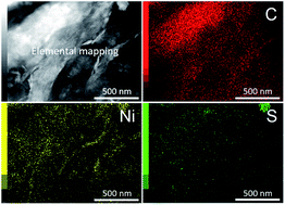
TEM images of both PNS and PNS/rGO40 composites are shown in Fig. 2. The PNS that was prepared using P123 shows a well-defined flake morphology. The nanoporous structure is clearly visible inside the flakes, as indicated by the circles (Fig. 2b), although the nanopores are not well arranged. The average lateral sizes are 80–100 nm. The framework is highly crystallized, and the lattice fringes are clearly observed over the entire area. The observed lattice fringes show a distance of 0.23 nm, which corresponds to the (220) plane of the nickel sulfide millerite phase. For comparison, BNS prepared without surfactants was also checked using SEM and TEM. The nickel sulfide particles do not possess any porous nature, and the particle size is much larger (Fig. S3). For PNS/rGO composites with low content of rGO sheets, the original flake-like morphology is basically confirmed; in some parts, the rGO sheets cover the nickel sulfide flakes (Fig. 3). When the loading amount of rGO is increased, the rGO sheets are completely encapsulated with nickel sulfide flakes. Introducing the nickel sulfide flakes as spacers prevents the restacking or aggregation of the rGO sheets. High-resolution TEM images of the PNS/rGO composites show two different types of lattice fringe values, as shown in Fig. 2d. Both the rGO sheets and nickel sulfide flakes are present in the composites. One lattice fringe with a d-spacing value of 0.38 nm corresponds to the (002) plane of rGO sheets, while the other lattice fringe with a d-spacing value of 0.23 nm can be indexed to the (220) plane of the trigonal nickel sulfide millerite phase. The surface coating and presence of rGO on the nickel sulfide flakes were further confirmed by elemental mapping (Fig. S4).


image file: c5ra26946f-f2.tif
Fig. 2 (a–d) TEM and HRTEM images of (a, b) PNS and (c, d) PNS/rGO40 composites.

image file: c5ra26946f-f3.tif
Fig. 3 SEM images of (a) PNS, (b) PNS/rGO20, (c) PNS/rGO40, and (d) PNS/rGO80 composites.

The average pore sizes and the surface areas of the samples were measured using N2 adsorption–desorption isotherms (Fig. S5). The PNS flakes and PNS/rGO composites show type IV isotherms with hysteresis loops in the range of 0.45–1.00. This behavior is due to the capillary condensation of N2 into the nanopores. PNS flakes prepared with surfactants show a high specific surface area (85.7 m2 g−1), as compared to BNS prepared without surfactants (18.2 m2 g−1) (Fig. S5c). The isotherm of BNS shows a type III isotherm, which is typical for nonporous materials (Fig. S5a).16 It was revealed that P123 serves as the template for forming the nanoporous structure. When the loading amount of rGO is increased to 40 wt%, the surface areas gradually increased. However, when the loading amount of rGO reaches 80 wt%, the surface area is decreased, due to the stacking of sheets. The isotherms for various composites of PNS/rGO are shown in Fig. S5b. The surface area values are 101.7 m2 g−1, 146.8 m2 g−1, and 94.1 m2 g−1 for PNS/rGO20, PNS/rGO40, and PNS/rGO80, respectively. The surface areas obtained in this study are quietly higher than those of other related materials reported previously (Table S1).17 Pore-size distribution of the PNS and the PNS/rGO composites calculated using the BJH method is very broad, in a range from 2 nm to 14 nm (Fig. S5d). The pore-size distribution for all PNS/rGO composites is almost the same. These pores with broad size distributions are formed in the interlayer space. Actually, the N2 adsorption isotherm gradually increases without exhibiting any clear capillary condensation step, which has been observed for well-ordered mesoporous materials.18

The possible formation mechanism of PNS flakes is proposed. In the first step, Ni2+ ions dissolved in the aqueous solution are decorated with the hydrophilic poly(ethylene oxide) part of the P123. This is because coordinated water molecules near the Ni2+ center interact with the poly(ethylene oxide) group of P123 through hydrogen bonding.19 Then, S2− ions are introduced into the reaction mixture through a thiourea solution. The formed S2− ions react with the Ni2+ ions, and nickel sulfide nuclei are formed. The nickel sulfide framework develops during the aging stage, in which the P123 micelles (as porogens) are assembled.20 The surface charges of PNS flakes and rGO sheets play an important role in preparing for the hybridization of nickel sulfide with rGO. The zeta potentials of the PNS flakes and the rGO sheets were measured to be +19.79 mV and −22.09 mV, respectively (Fig. S6). These positive and negative charges on the materials match with reports from previous literature.21 Therefore, positively charged nickel sulfide species can be effectively attached (or interacted) with the negatively charged rGO surface through electrostatic interaction. The zeta potential value of the PNS/rGO composite was +1.93 mV.

It is well known that crystal phases obtained are more sensitive to reaction temperatures, pressures, and reactant concentrations.22 In this study, the crystalline phases were found to be mainly dependent on the applied temperatures in hydrothermal conditions. The materials were prepared at four different temperatures (100 °C, 120 °C, 150 °C, and 180 °C). At 100 °C (i.e., typical condition), a single nickel sulfide phase with a 2D flake shape is obtained. The strong and sharp diffraction peaks confirm the high crystallinity of the obtained sample. When the synthetic temperature increased to above 100 °C (i.e., 120, 150, and 180 °C), the crystal phases are significantly changed to other phases, as shown in Fig. S2. This is probably due to the following two reasons: (i) an uncontrolled release of S2− ions in the reaction mixture and (ii) an increased crystallization rate.23 The morphologies of the obtained materials are also greatly affected by the applied temperatures. When the temperature is increased from 100 °C to 180 °C, the final morphology is changed from flakes to spheres (Fig. S7). As a result, a serious decrease in the specific area is confirmed. Consequently, the reaction temperatures in our case show a significant influence on the crystal phases and particle morphology.

Notably, the obtained trigonal millerite nickel sulfide phase has a highly conducting metallic character (∼2 × 10⁴ ohms−1 cm−1 at room temperature), as compared to other nickel sulfide phases.24 This is because the Ni–S bond length in trigonal millerite nickel sulfide (2.25 Å) is relatively shorter than those of hexagonal nickel sulfide (2.39 Å) and nickel disulfide (NiS2) (2.40 Å).24 This metallic character delivers superior electrical conductivity, which enhances efficient electron/ion transport in the electrode.25 This feature is essentially needed for real energy storage and conversion devices. However, the use of this type of material for supercapacitors has not yet been fully explored. Therefore, in this study, the PNS flakes with a trigonal millerite nickel sulfide phase were prepared using a hydrothermal process at 100 °C; they were also hybridized with rGO sheets to prepare PNS/rGO composites.

3.2. Electrochemical supercapacitor applications

The electrochemical performance of samples was studied using cyclic voltammetry (CV) experiments in a standard three-electrode system. Initially, comparative capacitive studies were carried out for all samples at various scan rates (5 to 100 mV s−1). The typical CVs for PNS and PNS/rGO40 are shown in Fig. 4a–b. For comparison, the specific capacitance of BNS was also calculated at the same scan speed and shows only 311.82 F g−1 of the capacitance value at a scan rate of 5 mV s−1. It is significantly lower than that of our PNS (1205 F g−1), indicating that porous structure plays a significant role in achieving high electrochemical performance. The specific capacitance values calculated from the CV curves are 1205, 933, 1312, and 846 F g−1 for PNS, PNS-rGO20, PNS-rGO40, and PNS-rGO80 composites, respectively, at a scan speed of 5 mV s−1. Due to uniform surface coating and reduced stacking effects of rGO, PNS/rGO40 composites with the highest BET surface area show the highest specific capacitance of 1312 F g−1 at a scan speed of 5 mV s−1, which is much better than those of other PNS/rGO composites.
image file: c5ra26946f-f4.tif
Fig. 4 (a–b) Cyclic voltammograms (CVs) measured at various scan rates for (a) PNS and (b) PNS/rGO40, (c) variation of specific capacitances with scan rates for PNS/rGO40, (d) specific capacitance retention during 500 cycles.

The obtained CV curve is almost symmetric, signifying good reversibility of the redox processes. CV shows a pair of redox peaks due to the faradic reactions of NiII and NiIII, which are due to the following possible reaction mechanism:10e

 
NiS + OH ↔ NiSOH + e−1 (5)
 
NiSOH + OH ↔ NiSO + H2O + e−1 (6)

As seen in Fig. 4a–b, as the applied scan rate is increased, the current increases, and the oxidation peak shifts to the more positive potential side, while the reduction peak shifts to the more negative potential side. Thus, the PNS and PNS/rGO40 composite exhibit good capacitive behavior and stable operation over a potential range of 0.0 to 0.6 V. The specific capacitance of the PNS/rGO40 composite as a function of the scan rate is plotted in Fig. 4c. From the CV curves, the specific capacitance values are determined to be 1312, 772, 550, 433, 357, and 302 F g−1 at different scan rates of 5, 20, 40, 60, 80, and 100 mV s−1, respectively.

Additional advantages of these composites include stability in their CV shape due to the presence of rGO. The CV studies were carried out for 500-CV cycles at 20 mV s−1. Although the PNS sample also showed high capacitance value, capacitance retention after 500 cycles was 86%. On the other hand, the PNS/rGO40 composite showed good capacitance retention of 94% (Fig. 4d). This fact clearly highlights the advantage of PNS/rGO composites for retaining capacitance value over long cycle operation for practical applications. Furthermore, in order to identify the role of nanoporous structures on supercapacitor performance, we compared the specific capacitance of our PNS flakes with those from previous literature for various nickel sulfide nanostructures, which clearly confirms that our capacitance values are higher than those of previous reports (Table S2).

To investigate the capacitive performance of PNS/rGO40 (showing a high performance in the three-electrode system mentioned above), an asymmetric supercapacitor (ASC) was fabricated using PNS/rGO40 as a positive electrode. In our previous studies, we demonstrated that ZIF-8-derived nanoporous carbon has a high specific surface area of ∼1500 m2 g−1 for supercapacitor applications.26 This nanoporous carbon (derived from ZIF-8) electrode has already shown its potential to substitute for activated carbon as a counter in supercapacitor applications. In the present study, ZIF-8-derived nanoporous carbon is used as a negative electrode. For the synthesis of ZIF-8 derived carbon and electrode fabrication, we followed the same process as in our previous reports.26b Fig. 5a shows the CV curves of ASCs in various higher potential window limits extending from 0.9 to 1.6 V at a scan rate of 20 mV s−1. The CV curves have a distorted rectangular shape with good reversibility, which may be due to the combined contributions of the electrodes. Thus, the maximum potential window of 0.0–1.6 V was chosen for the ASC investigation. When the upper potential exceeds 1.2 V, the presence of slight redox peaks indicates that the pseudocapacitive factor is coming from the sulfide reactions of the positive cell. The redox peak intensity increases with further increases in the potential window, similar to that seen in previous report.27 After 1.6 V, oxygen evaluation occurs.


image file: c5ra26946f-f5.tif
Fig. 5 (a) CV curves of an ASC device at various potential windows extending from 0.9 to 1.6 V, (b) galvanostatic charge–discharge (CD) studies of an ASC device with a cell voltage of 1.6 V at different specific currents, (c) variation of specific capacitances with specific currents, and (d) Ragone plots for our ASC device consisting of PNS/rGO40 and ZIF-8-derived carbon.

Furthermore, the electrochemical performance of the asymmetric cell was tested by galvanostatic charge–discharge tests conducted at various current densities ranging from 2 A g−1 to 9 A g−1, which are shown in Fig. 5b. All of the discharge curves show a combined pseudo-EDLC character, indicating a well-balanced charge storage and electrochemical reversibility of the materials. Our asymmetric device shows a specific capacitance value of 47.85 F g−1 at 2 A g−1 and decreased to 37.76 F g−1 at 9 A g−1, showing good rate capability. Also, 78.91% specific capacitance retention is obtained when the current density values are increased from 2 A g−1 to 9 A g−1 (Fig. 5c).

Fig. 5d shows the energy and power density of our ASC cell, obtained from charge–discharge curves. The ASC cell shows a higher specific energy of 17.01 W h kg−1 at a specific power of 2285.36 W kg−1 at a current density of 2 A g−1. The specific power is increased to 10[thin space (1/6-em)]283 W kg−1 at a current density of 9 A g−1 while maintaining the specific energy of 13.42 W h kg−1. Furthermore, our ASC exhibits improved energy density at high power density as compared with those previously reported, as summarized in Table S3. The high-rate performance and large-cell voltage of the aqueous electrolyte demonstrate the advantages of the PNS/rGO40 electrode for future supercapacitor applications.

4. Conclusion

In this work, we designed a simple soft-templating strategy to synthesize nanoporous nickel sulfide with 2D morphology using triblock copolymer pluronic P123 as a structure-directing agent. Due to the complex crystal structures of nickel sulfide, some mixed phases of nickel sulfide have been reported in most of the previous studies. However, in our study, we successfully controlled the nickel sulfide synthesis conditions and finally obtained a pure trigonal millerite nickel sulfide phase with high conductivity. Hybridization of rGO sheets with nickel sulfide flakes was also successfully achieved by considering the charges of each material. The synthesized PNS/rGO composites showed enhanced supercapacitor performance and good stability. This is due to the nanoporous architecture as well as improved conductivity due to the presence of graphene layers. The fabricated ASC device, consisting of a PNS-rGO40 composite and ZIF-8-derived carbon, showed a specific capacitance of 47.85 F g−1 at 2 A g−1. Furthermore, the electrode delivered a high-energy density of 17.01 W h kg−1, even at a power density of 10 kW kg−1. We strongly believe that our method can be extended to prepare other nanoporous metal sulfides with precisely controlled conducting phases, leading to the development of targeted supercapacitor applications in the future.

References

  1. (a) X. Lang, A. Hirata, T. Fujita and M. Chen, Nat. Nanotechnol., 2011, 6, 232–236 CrossRef CAS PubMed; (b) J. Jiang, Y. Li, J. Liu, X. Huang, C. Yuan and X. W. Lou, Adv. Mater., 2012, 24, 5166–5180 CrossRef CAS PubMed; (c) G. Wang, L. Zhang and J. Zhang, Chem. Soc. Rev., 2012, 41, 797–828 RSC; (d) C. D. Lokhande, D. P. Dubal and O. S. Joo, Curr. Appl. Phys., 2011, 11, 255–270 CrossRef.
  2. R. R. Salunkhe, J. Tang, Y. Kamachi, T. Nakato, J. H. Kim and Y. Yamauchi, ACS Nano, 2015, 9, 6288–6296 CrossRef CAS PubMed.
  3. (a) X. Rui, H. Tan and Q. Yan, Nanoscale, 2014, 6, 9889–9924 RSC; (b) M. R. Gao, Y. F. Xu, J. Jiang and S. H. Yu, Chem. Soc. Rev., 2013, 42, 2986–3017 RSC.
  4. (a) W. Wei, L. Mi, Y. Gao, Z. Zheng, W. Chen and X. Guan, Chem. Mater., 2014, 26, 3418–3426 CrossRef CAS; (b) F. Cai, R. Sun, Y. Kang, H. Chen, M. Chen and Q. Li, RSC Adv., 2015, 5, 23073–23079 RSC; (c) Y. Li, K. Ye, K. Cheng, J. Yin, D. Cao and G. Wang, J. Power Sources, 2015, 274, 943–950 CrossRef CAS.
  5. M. Acerce, D. Voiry and M. Chhowalla, Nat. Nanotechnol., 2015, 10, 313–318 CrossRef CAS PubMed.
  6. (a) C. Xu, Y. Zeng, X. Rui, N. Xiao, J. Zhu, W. Zhang, J. Chen, W. Liu, H. Tan, H. H. Hng and Q. Yan, ACS Nano, 2012, 6, 4713–4721 CrossRef CAS PubMed; (b) C. Zhang, H. Yin, M. Han, Z. Dai, H. Pang, Y. Zheng, Y. Q. Lan, J. Bao and J. Zhu, ACS Nano, 2014, 8, 3761–3770 CrossRef CAS PubMed.
  7. (a) A. Ghezelbash, M. B. Sigman and B. A. Korgel, Nano Lett., 2004, 4, 537–542 CrossRef CAS; (b) L. Shen, L. Yu, H. B. Wu, X. Y. Yu, X. Zhang and X. W. Lou, Nat. Commun., 2015, 6, 6694 CrossRef CAS PubMed; (c) L. Zhang, J. C. Yu, M. Mo, L. Wu, Q. Li and K. W. Kwong, J. Am. Chem. Soc., 2004, 126, 8116–8117 CrossRef CAS PubMed.
  8. (a) W. Zhou, W. Chen, J. Nai, P. Yin, C. Chen and L. Guo, Adv. Funct. Mater., 2010, 20, 3678–3683 CrossRef CAS; (b) S. H. Yu and M. Yoshimura, Adv. Funct. Mater., 2002, 12, 277–285 CrossRef CAS; (c) C. V. Thulasi-Varma, C. V. V. M. Gopi, S. S. Rao, D. Punnoose, S.-K. Kim and H.-J. Kim, J. Phys. Chem. C, 2015, 119, 11419–11429 CrossRef CAS; (d) L. Mi, Q. Ding, W. Chen, L. Zhao, H. Hou, C. Liu, C. Shen and Z. Zheng, Dalton Trans., 2013, 42, 5724–5730 CAS.
  9. Y. Wang, Q. Zhu, L. Tao and X. Su, J. Mater. Chem., 2011, 21, 9248–9254 RSC.
  10. (a) B. T. Zhu, Z. Wang, S. Ding, J. S. Chen and X. W. Lou, RSC Adv., 2011, 1, 397–400 RSC; (b) J. Yang, X. Duan, Q. Qin and W. Zheng, J. Mater. Chem. A, 2013, 1, 7880–7884 RSC; (c) H. Pang, C. Wei, X. Li, G. Li, Y. Ma, S. Li, J. Chen and J. Zhang, Sci. Rep., 2014, 4, 3577 Search PubMed; (d) J. Yang, X. Duan, W. Guo, D. Li, H. Zhang and W. Zheng, Nano Energy, 2014, 5, 74–81 CrossRef CAS; (e) A. Wang, H. Wang, S. Zhang, C. Mao, J. Song, H. Niu, B. Jin and Y. Tian, Appl. Surf. Sci., 2013, 282, 704–708 CrossRef CAS.
  11. R. R. Salunkhe, Y. H. Lee, K. H. Chang, J. M. Li, P. Simon, J. Tang, N. L. Torad, C. C. Hu and Y. Yamauchi, Chem.–Eur. J., 2014, 20, 13838–13852 CrossRef CAS PubMed.
  12. (a) R. Raccichini, A. Varzi, S. Passerini and B. Scrosati, Nat. Mater., 2015, 14, 271–279 CrossRef CAS PubMed; (b) M. Beidaghi and Y. Gogotsi, Energy Environ. Sci., 2014, 7, 867–884 RSC.
  13. H. Zhang, X. Yu, D. Guo, B. Qu, M. Zhang, Q. Li and T. Wang, ACS Appl. Mater. Interfaces, 2013, 5, 7335–7340 CAS.
  14. (a) M. Ouzzine, J. A. Maciá-Agulló, M. A. Lillo-Ródenas, C. Quijada and A. Linares-Solano, Appl. Catal., B, 2014, 154–155, 285–293 CrossRef CAS; (b) X. Liu, B. Tian, C. Yu, F. Gao, S. Xie, B. Tu, R. Che, L.-M. Peng and D. Zhao, Angew. Chem., Int. Ed., 2002, 41, 3876–3878 CrossRef CAS.
  15. R. R. Salunkhe, S. H. Hsu, K. C. Wu and Y. Yamauchi, ChemSusChem, 2014, 7, 1551–1556 CrossRef CAS PubMed.
  16. (a) M. Kruk and M. Jaroniec, Chem. Mater., 2001, 13, 3169–3183 CrossRef CAS; (b) P. Yang, D. Zhao, D. I. Margolese, B. F. Chmelka and G. D. Stucky, Nature, 1998, 396, 152–155 CrossRef CAS.
  17. B. T. Yonemoto, G. S. Hutchings and F. Jiao, J. Am. Chem. Soc., 2014, 136, 8895–8898 CrossRef CAS PubMed.
  18. V. Malgras, Q. Ji, Y. Kamachi, T. Mori, F.-K. Shieh, K. C. W. Wu, K. Ariga and Y. Yamauchi, Bull. Chem. Soc. Jpn., 2015, 88, 1171–1200 CrossRef CAS.
  19. P. Alexandridis, R. Ivanova and B. Lindman, Langmuir, 2000, 16, 3676–3689 CrossRef CAS.
  20. (a) F. Xu, Y. Xie, X. Zhang, C. Wu, W. Xi, J. Hong and X. Tian, New J. Chem., 2003, 27, 1331–1335 RSC; (b) Y. Ma, L. Qi, J. Ma, H. Cheng and W. Shen, Langmuir, 2003, 19, 9079–9085 CrossRef CAS.
  21. (a) W. S. Chi, J. W. Han, S. Yang, D. K. Roh, H. Lee and J. H. Kim, Chem. Commun., 2012, 48, 9501–9503 RSC; (b) R. Wang, Y. Wang, C. Xu, J. Sun and L. Gao, RSC Adv., 2013, 3, 1194–1200 RSC.
  22. (a) B. Jang, M. Park, O. B. Chae, S. Park, Y. Kim, S. M. Oh, Y. Piao and T. Hyeon, J. Am. Chem. Soc., 2012, 134, 15010–15015 CrossRef CAS PubMed; (b) R. W. Y. Man, A. R. C. Brown and M. O. Wolf, Angew. Chem., Int. Ed., 2012, 51, 11350–11353 CrossRef CAS PubMed.
  23. A. M. Qin, Y. P. Fang, H. D. Ou, H. Q. Liu and C. Y. Su, Cryst. Growth Des., 2005, 5, 855–860 CAS.
  24. S. R. Krishnakumar, N. Shanthi and D. D. Sarma, Phys. Rev. B, 2002, 66, 115105 CrossRef.
  25. P. K. Kannan and C. S. Rout, Chem.–Eur. J., 2015, 21, 9355–9359 CrossRef CAS PubMed.
  26. (a) R. R. Salunkhe, H. Ahn, J. H. Kim and Y. Yamauchi, Nanotechnology, 2015, 26, 204004 CrossRef PubMed; (b) R. R. Salunkhe, Y. Kamachi, N. L. Torad, S. M. Hwang, Z. Sun, S. X. Dou, J. H. Kim and Y. Yamauchi, J. Mater. Chem. A, 2014, 2, 19848–19854 RSC.
  27. J. Ji, L. L. Zhang, H. Ji, Y. Li, X. Zhao, X. Bai, X. Fan, F. Zhang and R. S. Ruoff, ACS Nano, 2013, 7, 6237–6243 CrossRef CAS PubMed.

Footnote

Electronic supplementary information (ESI) available. See DOI: 10.1039/c5ra26946f

This journal is © The Royal Society of Chemistry 2016