
Surface-enhanced Raman scattering (SERS) detection of fluorosurfactants in firefighting foams†
C. Fang‡
*ab,
M. Megharaj‡ab and
R. Naidu‡*ab
aGlobal Centre for Environmental Remediation (GCER), University of Newcastle, ATC Building, Callaghan, NSW 2308, Australia. E-mail: cheng.fang@newcastle.edu.au; ravi.naidu@crccare.com
bCooperative Research Centre for Contamination Assessment, Remediation of the Environment (CRCCARE), University of Newcastle, ATC Building, Callaghan, NSW 2308, Australia
First published on 21st January 2016
Abstract
We demonstrated SERS (surface-enhanced Raman scattering) detection of fluorosurfactants (FSs), which are commonly formulated in aqueous firefighting foams (AFFFs), by increasing their loading affinity and boosting their Raman activity. In order to increase FS's loading affinity, we introduced a cationic dye (ethyl violet or methyl blue) into the aqueous incubation solution to co-precipitate the FS onto the SERS substrate surface by forming an immiscible ion-pair (dye–FS). In the meantime, the Raman signal intensity was boosted due to the much higher Raman activity of the dye than that of FS. We compared two kinds of SERS substrate, patterned silver (Ag) surface and graphene oxide (GO) membrane, and noted the former (dye–FS–Ag) enhanced the Raman signal whilst the latter (dye–FS–GO) increased the loading affinity of the ion-pair due to the hydrophobic surface. We thus introduced silver nanoparticles (AgNPs) into the incubation solution (as well as dye) to co-precipitate FS onto the GO surface via an assembly of dye–FS–AgNP–GO. Using this assembly, we successfully detected FSs including pentadecafluorooctanoic acid (PFOA), perfluorooctanesulfonic acid (PFOS), and 1H,1H,2H,2H-perfluorooctanesulfonic acid (6:2FTS), with a limit-of-detection (LOD) of ∼50 ppb (∼120 nM) for PFOA.
Introduction
Aqueous firefighting foams (AFFFs), containing fluorosurfactants (FSs) as anionic surfactants to form foam-films, have been widely used in fire-related activities due to FSs' thermal/chemical stability and their high capacity to extinguish fuel and hydrocarbon fires.1,2 Unfortunately, it is extremely difficult to degrade these inert fluoro-carbon skeletons in the natural environment. Consequently, use of AFFFs and the emissions from other sources like fluoropolymer manufacture, ammonium perfluorooctanoate and fluoropolymer dispersion,3–6 have led to perfluoroalkyl substances' global distribution and their continuous accumulation eventually affected human and environmental health.7,8Much effort has been made to develop a tool for detecting FSs. The most common method is based on the extraction of active ingredients from water using an organic phase, such as chloroform in methylene blue (MB) active substrates.9 Chloroform, however, raises concerns due to its toxicity and hence substitution has been developed.10 Other methods include HPLC8 and capillary electrophoresis.11 Those technologies offer a good range of detection but suffer from severe limitations: firstly, they are expensive; and secondly and more generally, they are not suitable for on-site application. Electrochemical test has also been developed but the stability of the sensing membrane was a challenge.12,13
Surface-enhanced Raman scattering (SERS) has attracted much attention due to its high sensitivity (down to single molecule detection), capacity for molecular identification and lack of interference from water (compared to infrared).14,15 The extremely high enhancement from the substrate surface is categorized into electro-magnetic and chemical enhancements, respectively.14,16 Most of the substrates are made of metals. To date there have been many types of SERS substrates, for example roughened metal surfaces,17 nanoparticle (NP) arrays,16,18 nanofabricated surfaces19 and nanoaggregates, etc.20,21 Of these, nanosphere lithography and nanoparticle array have certain advantages including simple fabrication, ease of scaling-up for centimetre size, uniform surface with high enhancement, etc.22,23 However, the loading affinity of some target moieties is an issue due to their hydrophilic surface, particularly when considering FS's oleophobic characteristics.
Since the successful isolation of the graphene monolayer in 2004, considerable interest has been paid to this carbon material sp2-hybridized into a honeycomb network.24–26 Interestingly, graphene and graphene oxide (GO) have been successfully demonstrated as SERS substrates.27–30 Compared to traditional metal surfaces (for instance, silver, gold and copper) that are usually hydrophilic, GO is an organic material with a hydrophobic carbon network, which might lead to the increased loading affinity of some organic targets onto its surface for improvement.30,31 Furthermore, by introducing silver nanoparticles (AgNPs) onto the GO membrane to form dual-substrate, we supposedly combine the strong enhancement of AgNP array with the high loading affinity of GO surface for FSs.
Herein, we compared those two SERS substrates, nanosphere lithography Ag and GO membrane to confirm the high loading affinity of GO surface for FSs. Rather than directly loading FS onto SERS substrate surface, we loaded the ion-pair of dye–FS precipitate. The dye also behaved as the Raman probe due to its much higher Raman activity than that of FS. Triphenylmethane dye of ethyl violet (EV) was selected for comparison to MB.9,10 We then incubated GO membrane in an aqueous solution containing FS, dye and AgNP for an assembly of dye–FS–AgNP–GO to combine the following: (i) strengthened loading affinity of FSs by GO; (ii) high Raman activity of dye; (iii) strong enhancement of AgNP array and (iv) dye–FS precipitate to further loading affinity and selectivity of FS. We selected pentadecafluorooctanoic acid (PFOA), perfluorooctanesulfonic acid (PFOS) and 1H,1H,2H,2H-perfluorooctanesulfonic acid (6:2FTS) as FS models,32 sodium dodecyl sulphate (SDS) and dodecylbenzenesulfonic acid (a linear alkylbenzene sulfonate, LAS) as anionic surfactant models.
Results and discussion
Dye–FS
Fig. 1(a) and (b) show the photo images of the EV–FS ion-pairs. The colour in the presence of FS differs from the blank EV, suggesting the formation of EV–FS ion-pairs.9,33 Most ion-pairs have precipitated overnight due to their low solubility (immiscible) in the aqueous solutions. Of these, EV–PFOA seemingly exhibits the least solubility because the solution looks clean one day later. Therefore, we focused on PFOA in this report hoping to achieve a lower limit of detection (LOD). | ||
| Fig. 1 Photo images (a and b) and UV-vis spectra (c). Blank EV is shown to compare with EV–FS ion-pairs. The concentration of EV was 10 mg L−1 (ppm) whilst anionic surfactants (indicated) was 50 mg L−1 (ppm). The storage periods were indicated in (a and b). The spectra in (c) were collected from the fresh solutions. | ||
Fig. 1(c) shows the UV-vis spectra of the EV in the presence of anionic surfactants. Note that all the spectra were collected within 10 min following the introduction of anionic surfactants into the EV solution (fresh). Compared with the blank EV solution (10 mg L−1, 10 ppm), the intensity of EV was decreased (20–50%) by anionic surfactants, suggesting the precipitation of ion-pairs and shrinking of EV concentration.34 The peak's position was also shifted or modified, but agreed with the colour modification in Fig. 1(a) and (b).
Therefore, by introducing a dye into the aqueous solution to form an immiscible ion-pair,9 we can subsequently increase the FS's loading affinity, such as onto SERS substrate surface.
Dye–FS–Ag
To confirm the above assumption, we used a colloid-lithography Ag layer (Ag surface) as a SERS substrate (Fig. 2(a)) to collect the immiscible ion-pair precipitated from aqueous incubation solution. During the incubation process, the SERS substrate lay on the sharp bottom of a centrifuge tube with the Ag surface facing up to collect all the precipitate. The results are shown in Fig. 3. Note there are several spectra presented simultaneously when they were collected randomly on the SERS substrate surface from spot to spot in air (differing from the UV-vis spectra collected from the fresh solutions). Considering the signal intensity, which usually varies with a magnitude of 10–30% due to the electro-magnetic field variation in the hot-spot (from substrate to substrate and from spot to spot),17 the reproducibility of this is considered to be good. On the other hand, the raw data herein might be optimised to improve robust response either by prolonging the collection period, by scanning the laser spot for one spectrum collection (not restricted on a local position), or by employing algorithm (averaging several spectra or smoothening them, as shown in Fig. 3(b)).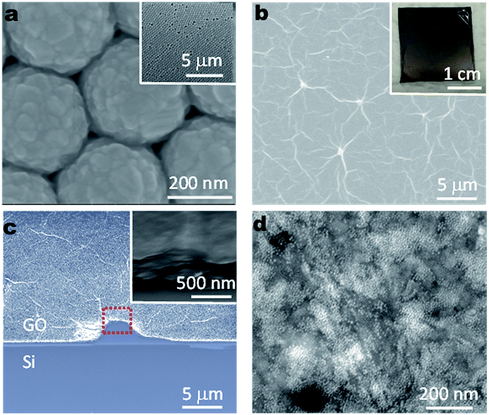 | ||
| Fig. 2 SEM images of the SERS substrates. (a) Shows the silica nanosphere (SiNS) lithography surface where a layer of Ag was deposited (with a thickness of ∼200 nm) on the top of a monolayer of SiNS. (b and c) Depict the GO membrane of the top-view (b) and the side-view with a titling angle ∼30° (c). (d) Illustrates the AgNPs deposited on GO surface. All insets are under different magnifications. | ||
 | ||
| Fig. 3 Raman spectra of the assembly of dye–FS–Ag. All spectra were collected from the Ag surface shown in Fig. 2(a). The incubation solutions contained 0.1 ppm EV, 10 mM NaCl (“Control”) and 5 ppm FS. FS was PFOA in (a and b), PFOS in (c) or 6:2FTS in (d), respectively. (b) Shows the typical spectra in the finger-print range from (a) after averaging. | ||
In Fig. 3(a), the spectra looks similar, suggesting the main contributor for the Raman scattering originates from the EV dye (in the “Control”), rather than from PFOA. However, there are two main differences between the spectra of EV–PFOA and that of EV (“Control”): (i) the appearance of a broad peak in the range of 2500–4000 cm−1; and (ii) the strengthened (5–20 times) Raman scattering compared to the “Control”. Regarding the former (i), the broad peak is commonly assigned to the fluorescence background. It has been reported that the triphenylmethane dye itself exhibits a weak fluorescence whilst the fluorescence can be significantly increased when the ion-pair in aqueous solution has formed.35 Fortunately, this wavenumber range does not interfere with the Raman finger-print range of organic molecules, 0–1800 cm−1, as shown in Fig. 3(b) (characteristic peaks are marked to identify the dye probe of EV).
With respect to the latter (ii), the strengthened Raman scattering means either the amount of loaded EV molecules has been increased, or the Raman activity of EV–PFOA ion-pair is stronger than that of EV.36,37 However, we did not observe the peaks' position shifting in Fig. 3(b), implying that molecular configuration modification made only a limited contribution. The main explanation for this is that the loading amount of EV has been amplified. Because the EV–FS ion-pair had a much lower solubility than EV in aqueous solution, its loading affinity onto the SERS substrate has been increased. Note the Raman signal of PFOA is not observed here due to its low Raman activity (ESI, Fig. S1†).
Similar results were observed for PFOS, 6:2FTS (Fig. 3(c) and (d)), SDS and LAS (not shown here). These confirm the above assumption that the formation of the ion-pair EV–FS can increase the loading affinity and boost the Raman activity by measuring EV's signal rather than FS. We hence selected EV as a Raman probe for the detection of FS.
Dye–FS–GO
Although most SERS substrates are made of Ag or gold, GO has also been recently explored as SERS substrate.27–30 Because the EV dye is an organic moiety, it is assumed that the ion-pair EV–FS can be loaded onto the hydrophobic GO surface more easily than onto the hydrophilic Ag surface.28,31 To confirm this assumption, we prepared GO membrane on the silicon surface (ESI, Fig. S2†) for the following experiments.38 The morphology is presented in Fig. 2(b) and (c). The surface is smooth to load the target samples via adsorbing rather than trapping or embedding, etc.In Fig. 4(a), the GO membrane has been incubated in a solution of 5 ppm PFOA + 1 ppm EV + 10 mM NaCl overnight. For comparison, an EV spectrum was shown when it has been collected from an Ag surface where only EV was loaded. It is interesting to notice that the characteristic peaks' intensity of EV is of 2–5 times of that from the GO surface. Because the comparable Raman signal has been significantly enhanced on the Ag surface, that Raman scattering should also be enhanced on the GO surface,27–30 although not as significantly as on the Ag surface.
 | ||
| Fig. 4 Raman spectra of the assembly of dye–FS–GO. All spectra were collected from the GO surface shown in Fig. 2(b) and (c). The incubation solutions were 1 ppm EV (a–c) or MB (d), 10 mM NaCl and 5 ppm FS. FS was PFOA in (a and d), PFOS in (b) or 6:2FTS in (c), respectively. In the absence of FS, the spectra of dye are presented for comparison, which were collected from Ag surface (a and d) (EV/MB) and GO membrane surface (b–d) (Control). | ||
In Fig. 4(b) and (c), “Control” was collected when the GO membrane (not Ag surface) was incubated in a solution of 1 ppm EV + 10 mM NaCl (no FS). Compared to “Control”, EV's characteristic peaks have been increased (2–20 fold), again, confirming the assumption that the presence of a dye can increase the loading affinity of FS onto GO surface. Note that PFOA has been replaced with PFOS (Fig. 4(b)), 6:2FTS (Fig. 4(c)), respectively.
To further confirm the above assumption, we changed another component in the ion-pair of dye–FS, the dye, from EV to MB. The results are presented in Fig. 4(d). Similarly, we can clearly identify the characteristic peaks of MB when compared with the standard spectrum of MB that was collected from Ag surface (1/2 to 1/5 in terms of the characteristic peaks' intensity), indicating the enhancement from the GO membrane surface. Compared with the “Control” that was also collected from GO surface in the absence of any FS, the intensity has been enhanced, suggesting the loading affinity has been increased too.
LOD
In Fig. 5(a), we checked the LOD of EV on the Ag surface, which seems to be 50 ppb (signal/noise > 3 at the marked peaks). A higher concentration (0.5 ppm and 5 ppm) emits a stronger signal whilst the lower one has almost no characterized signal (5 ppb). We thus selected 5 ppb of EV as the Raman probe to detect PFOA as “Control”. In this case the “Control” refers to a blank and clean background. | ||
| Fig. 5 LOD of the assemblies of dye–FS–Ag (a and b) and dye–FS–GO (c and d). The incubation solutions contained dye in (a and c) or dye + PFOA in (b and d) (concentrations were indicated). | ||
In Fig. 5(b), we fixed the probe (EV) concentration at 5 ppb whilst adjusting the concentration of PFOA. The dependence of signal (characteristic peaks' intensity) on the concentration of PFOA (500 ppb to 50 ppm) offers the promise for semi-quantitative test. The LOD was ∼500 ppb (signal/noise > 3) for PFOA. This value is encouraging for AFFFs SERS detection.
Similarly, the LOD of EV on GO membrane surface was 500 ppb so we selected 50 ppb EV as the Raman probe for FS detection on GO surface, as presented in Fig. 5(c). Here the silicon peak at 512 cm−1 served as an internal standard when the GO membrane was thin. In Fig. 5(d), the signal's dependence on the concentration is not so obvious as that in Fig. 5(b), suggesting a lower sensitivity due to the limited enhancement of GO (compared to Ag). The LOD of PFOA was also ∼500 ppb in Fig. 5(d). Note the probe EV's concentration (50 ppb) on GO surface was 10 times higher than on Ag surface (5 ppb) due to the stronger enhancement from the Ag surface. However, the LOD of PFOA is similar (∼500 ppb) from both SERS substrate (signal/noise > 3). The reason was that the higher loading capacity on GO surface compensates the higher enhancement on Ag surface.
Dye–FS–AgNP–GO
To combine the high loading affinity of GO surface and the strong enhancement of Ag surface, we incubated the GO membrane in an aqueous solution containing PFOA + EV + AgNP + NaCl. Here the AgNP was introduced by adding an AgNP colloid into the incubation solution (diluting) and served as the Ag surface for enhancement. The topography of the substrate surface is presented in Fig. 2(d) while the test results are shown in Fig. 6. Similarly, in Fig. 6(a) in the absence of PFOA, we identified 5 ppb EV as the background. Subsequently, in Fig. 6(b), LOD of 50 ppb of PFOA was reached using the dye–FS–AgNP–GO assembly, thus providing evidence for the hypothesis. Using the developed assembly, 100 ppb of PFOA was successfully detected when spiked into groundwater, as demonstrated in Fig. 6(c). Note the clean background of the Raman spectrum might be attributed to the selective precipitation of FS with the help of dye and the subsequent washing procedure prior to the Raman test. The intensity of characteristic peaks in Fig. 6(c) of 100 ppb is between these of 50–500 ppb in Fig. 6(b), suggesting the satisfy recovery. | ||
| Fig. 6 LOD of the assembly of dye–FS–AgNP–GO. All spectra were collected from the AgNP–GO surface shown in Fig. 2(d). The incubation solutions contained dye (a) or dye + PFOA (b) (concentrations were indicated). (c) Shows the result of 100 ppb PFOA spiked in a groundwater using the developed assembly. | ||
Admittedly, positive response from other anionic surfactants rather than FS should not be ignored if they also feature the immiscible ion-pair with the dye. Therefore, sample preparation should be carried out to avoid those kinds of interferences and also to enhance the LOD through pre-selection and pre-concentration. Fortunately, the interference from other anionic surfactants at the FS-contaminated site is rare, such as the groundwater sample tested here. Compared to the similar approach using dye for SERS analysis, such as DNA test,19 the dye in this report works not only as a Raman probe, but also as a co-participant to diminish solubility of the target, FSs, in this report.
Conclusions
In general, we successfully detected AFFF fluorosurfactants including PFOA, PFOS and 6:2FTS using SERS. Due to the Raman probe's (EV or MB) Raman activity being much higher than FSs, we collected the probe Raman signal rather than AFFF FS itself. This Raman probe also increased the loading affinity of FSs onto the SERS substrate surface by forming the immiscible ion-pair precipitate in aqueous solution. Because the GO membrane had a higher loading capacity whilst the Ag featured a strong enhancement, FS was detected on the combined dual-substrate surface with a LOD of ∼50 ppb for PFOA. This encouraging result validated the SERS application for AFFF detection as a pre-screening tool.Experimental
Chemicals and materials
All chemicals including silica nanosphere (SiNS, Φ 300 nm), AgNP (Φ 10 nm), EV, MB, PFOA, PFOS, 6:2FTS, SDS and LAS were purchased from Sigma-Aldrich (Australia) and were used as supplied. Graphene oxide (GO) (ACS materials, 0.5 mg mL−1) was sonicated for at least 120 min before using.Preparation of Ag SERS substrate
Prior to SiNS deposition, the silicon wafer was cleaned by dipping it into Piranha solution (2![[thin space (1/6-em)]](https://www.rsc.org/images/entities/char_2009.gif) :1 H2SO4:H2O2, v/v) (be careful, this solution reacts vigorously with organic compounds!) overnight to remove any possible organic contaminants, then into SC-1 solution (5:1:1 H2O:NH3:H2O2, v/v) for ∼60 min at 70–80 °C to remove residual impurities.39
:1 H2SO4:H2O2, v/v) (be careful, this solution reacts vigorously with organic compounds!) overnight to remove any possible organic contaminants, then into SC-1 solution (5:1:1 H2O:NH3:H2O2, v/v) for ∼60 min at 70–80 °C to remove residual impurities.39
Ag SERS substrate was prepared as before.40 In general, on a clean silicon surface (∼2 cm × 2 cm), SiNS solution (∼10 μL) was dropped and spin-coated at 100 rpm for 2 min using a spin coater (WS-400B-6NPP/LITE, Laurell, USA). Subsequently, the spinning speed was increased to 800 rpm for 30 s to remove stacked multilayers of NS in order to obtain a monolayer template. After drying in air, the next step was to sputter coat a thin bottom layer of Ag (with a thickness of ∼300 nm) onto the template of monolayer SiNS using a Quorum tech sputter coater (K575X, Australia).
Preparation of GO SERS substrate
Similarly, on a clean silicon surface, ∼10 μL GO solution (0.5 mg mL−1) was spread to cover the surface with a spinning rate of 100 rpm for 10 min. The wafer was dried in air overnight at room temperature (∼24 °C).Loading of sample onto SERS substrate
Usually the SERS substrate was incubated in the aqueous solution containing FS sample overnight. In order to load ion-pair (dye–FS) rather than dye on the substrate, the concentration of FS was at least 5 times bigger than the dye in the incubation solution.34 10 mM NaCl (pH of ∼5.8 and conductivity of ∼1 mS cm−1) was presented in the incubation solution either in order to further enhance the Raman signal on Ag surface,40 or to increase the loading affinity due to salting-out interaction,35 or to mimic the underground water sample. To form a dye–FS–AgNP–GO assembly, AgNP was also presented in the incubation solution after 10 times dilution (v/v to 0.002 mg mL−1) from the original solution. Ground water was collected from Williamtown, Australia with pH of ∼6.3 and conductivity of ∼0.77 mS cm−1. After filtered with nylon syringe filter (∼0.2 μm), PFOA was spiked and marked as a real sample to evaluate the developed assembly.After loading, the SERS substrate was washed with Milli-Q water and gently dried with nitrogen blow. It is noted that GO membrane is easily lifted up and peeled off from the surface during the washing process so it needs to be handled carefully. The Raman tests were carried out within 24 hours when stored in air.
Surface characterization
Scanning electron microscopy (SEM) (Quanta 450, FEI Co., USA) was employed to characterize the surface topography of the substrate. UV-vis spectra were collected via Agilent 8453.Raman characterization
All Raman spectra were collected in air using a Witec confocal Raman microscope (Alpha 300RS, Germany) equipped with a 532 nm laser diode (<60 mW). For robust test, the laser intensity was fixed as a constant during the signal collection process. A CCD detector (cooled to −60 °C) was used to collect Stokes Raman signals under a 100× objective (Nikon) at room temperature over the wavenumber range of 0–2000 cm−1 with an integration time of 5 s for measurements of single spectra. For clarity of presentation, all the Y-scales have been off-set in this report unless indicated.Acknowledgements
The authors kindly acknowledge funding support from the Australian Government Department of Defence, and CRC CARE.Notes and references
- R. Naidu, Current research, understandings and future research, 5th International Contaminated Site Remediation Conference, Melbourne, Australia, September 15–18, 2013, p. A23 Search PubMed.
- A. Kärrman, K. Elgh-Dalgren, C. Lafossas and T. Møskeland, Environ. Chem., 2011, 8, 372–380 CrossRef.
- R. C. Buck, J. Franklin, U. Berger, J. M. Conder, I. T. Cousins, P. de Voogt, A. A. Jensen, K. Kannan, S. A. Mabury and S. P. J. van Leeuwen, Integr. Environ. Assess. Manage., 2011, 7, 513–541 CrossRef CAS PubMed.
- Z. Wang, I. T. Cousins, M. Scheringer, R. C. Buck and K. Hungerbühler, Environ. Int., 2014, 70, 62–75 CrossRef CAS.
- Z. Wang, I. T. Cousins, M. Scheringer, R. C. Buck and K. Hungerbühler, Environ. Int., 2014, 69, 166–176 CrossRef CAS PubMed.
- K. Prevedouros, I. T. Cousins, R. C. Buck and S. H. Korzeniowski, Environ. Sci. Technol., 2006, 40, 32–44 CrossRef CAS PubMed.
- S. Taniyasu, K. Kannan, Y. Horii, N. Hanari and N. Yamashita, Environ. Sci. Technol., 2003, 37, 2634–2639 CrossRef CAS PubMed.
- B. Boulanger, J. Vargo, J. L. Schnoor and K. C. Hornbuckle, Environ. Sci. Technol., 2004, 38, 4064–4070 CrossRef CAS PubMed.
- A. L. George and G. F. White, Environ. Toxicol. Chem., 1999, 18, 2232–2236 CrossRef CAS.
- M. Megharaj, N. Ravendra and P. Mercurio, Anionic surfactant detection, US patent application No. 20110097815, US Patent Office, Washington, DC, 2011 April 28.
- R. Knob, V. Maier, J. Petr, V. Ranc and J. Ševčík, Electrophoresis, 2012, 33, 2159–2166 CrossRef CAS PubMed.
- C. Fang, Z. Chen, M. Megharaj and R. Naidu, Environmental Technology & Innovation, 2016, 5, 52–59 Search PubMed.
- L. D. Chen, C.-Z. Lai, L. P. Granda, M. A. Fierke, D. Mandal, A. Stein, J. A. Gladysz and P. Bühlmann, Anal. Chem., 2013, 85, 7471–7477 CrossRef CAS PubMed.
- L. Tong, T. Zhu and Z. Liu, Chem. Soc. Rev., 2011, 40, 1296–1304 RSC.
- R. A. Halvorson and P. J. Vikesland, Environ. Sci. Technol., 2010, 44, 7749–7755 CrossRef CAS PubMed.
- C. Fang, D. Brodoceanu, T. Kraus and N. H. Voelcker, RSC Adv., 2013, 3, 4288–4293 RSC.
- C. Fang, A. V. Ellis and N. H. Voelcker, J. Electroanal. Chem., 2011, 659, 151–160 CrossRef CAS.
- C. Fang, A. Agarwal, E. Widjaja, M. V. Garland, S. M. Wong, L. Linn, N. M. Khalid, S. M. Salim and N. Balasubramanian, Chem. Mater., 2009, 21, 3542–3548 CrossRef CAS.
- C. Fang, A. Agarwal, K. D. Buddharaju, N. M. Khalid, S. M. Salim, E. Widjaja, M. V. Garland, N. Balasubramanian and D.-L. Kwong, Biosens. Bioelectron., 2008, 24, 216–221 CrossRef CAS PubMed.
- J. M. Martin, Y. L. Xing, H. Joel and Y. Peidong, J. Am. Chem. Soc., 2010, 132, 268–274 CrossRef PubMed.
- Y. L. Seung, H. Ling, S. L. Garrett, E. C. Jane, D. M. Isaak and O. Rabin, ACS Nano, 2010, 4, 5763–5772 CrossRef PubMed.
- K. B. Biggs, J. P. Camden, J. N. Anker and R. P. V. Duyne, J. Phys. Chem. A, 2009, 113, 4581–4586 CrossRef CAS PubMed.
- C. L. Haynes and R. P. Van Duyne, J. Phys. Chem. B, 2001, 105, 5599–5611 CrossRef CAS.
- K. S. Novoselov, A. K. Geim, S. V. Morozov, D. Jiang, Y. Zhang, S. V. Dubonos, I. V. Grigorieva and A. A. Firsov, Science, 2004, 306, 666–669 CrossRef CAS PubMed.
- M. J. Allen, V. C. Tung and R. B. Kaner, Chem. Rev., 2009, 110, 132–145 CrossRef PubMed.
- Y. Shao, J. Wang, H. Wu, J. Liu, I. A. Aksay and Y. Lin, Electroanalysis, 2010, 22, 1027–1036 CrossRef CAS.
- C. Qiu, H. Zhou, H. Yang, M. Chen, Y. Guo and L. Sun, J. Phys. Chem. C, 2011, 115, 10019–10025 CAS.
- X. Liu, L. Cao, W. Song, K. Ai and L. Lu, ACS Appl. Mater. Interfaces, 2011, 3, 2944–2952 CAS.
- X. Ling, L. Xie, Y. Fang, H. Xu, H. Zhang, J. Kong, M. S. Dresselhaus, J. Zhang and Z. Liu, Nano Lett., 2009, 10, 553–561 CrossRef PubMed.
- K. P. Loh, Q. Bao, G. Eda and M. Chhowalla, Nat. Chem., 2010, 2, 1015–1024 CrossRef CAS PubMed.
- Y. Li, Q. Du, T. Liu, X. Peng, J. Wang, J. Sun, Y. Wang, S. Wu, Z. Wang, Y. Xia and L. Xia, Chem. Eng. Res. Des., 2013, 91, 361–368 CrossRef CAS.
- C. Fang, M. Megharaj and R. Naidu, Environ. Toxicol. Chem., 2015, 34, 2625–2628 CrossRef CAS PubMed.
- S. Yamamoto, S. Kobashi, K.-i. Tsutsui and Y. Sueishi, Spectrochim. Acta, Part A, 2007, 66, 302–306 CrossRef PubMed.
- R. Patel and K. Singh Patel, Analyst, 1998, 123, 1691–1695 RSC.
- S. Moore, K. Glenn and R. Palepu, J. Solution Chem., 2007, 36, 563–571 CrossRef CAS.
- C. L. Haynes, A. D. McFarland and R. P. V. Duyne, Anal. Chem., 2005, 77, 338 A–346 A CrossRef CAS.
- P. L. Stiles, J. A. Dieringer, N. C. Shah and R. P. Van Duyne, Annu. Rev. Anal. Chem., 2008, 1, 601–626 CrossRef CAS.
- G. K. Ramesha, A. Vijaya Kumara, H. B. Muralidhara and S. Sampath, J. Colloid Interface Sci., 2011, 361, 270–277 CrossRef CAS PubMed.
- A. Sherman, J. Electrochem. Soc., 1990, 137, 1892–1897 CrossRef CAS.
- C. Fang, N. M. Bandaru, A. V. Ellis and N. H. Voelcker, Biosens. Bioelectron., 2013, 42, 632–639 CrossRef CAS PubMed.
Footnotes |
| † Electronic supplementary information (ESI) available. See DOI: 10.1039/c5ra26114g |
| ‡ Formerly at Centre for Environmental Risk Assessment and Remediation (CERAR), Mawson Lakes, University of South Australia, SA 5095, Australia. |
| This journal is © The Royal Society of Chemistry 2016 |