
Preparation of structurally colored films assembled by using polystyrene@silica, air@silica and air@carbon@silica core–shell nanoparticles with enhanced color visibility†
Fen Wang*,
Xin Zhang,
Jianfeng Zhu and
Ying Lin
School of Materials Science and Engineering, Shaanxi University of Science and Technology, Xi'an 710021, China. E-mail: wangf@sust.edu.cn; Fax: +86 02986168688; Tel: +86 15114805183
First published on 22nd March 2016
Abstract
Polystyrene@silica (PS@SiO2) core–shell nanospheres were synthesized using a surfactant free method followed by a modified Stöber method in the research reported in this paper. Hollow SiO2 was obtained by calcining the PS@SiO2 core–shell nanoparticles (NPs) at 500 °C in air and air@C@SiO2 (where C represents carbon) was prepared by calcining PS@SiO2 in argon (Ar). Scanning electron microscopy and transmission electron microscopy were used to confirm the formation of a homogeneous SiO2 shell on the negatively charged PS beads. Energy dispersive X-ray spectroscopy element mapping was utilized to confirm the existence and homogeneity of the C layer in the air@C@SiO2 nanospheres. After calcination, C partly remained inside the SiO2 shell and functioned as an absorbent material. The advantages of using negatively charged PS beads to prepare PS@SiO2 core–shell NPs and calcination of PS@SiO2 in Ar to prepare hollow SiO2 are: (1) the lower cost compared with the positively charged PS beads, because the negatively charged PS beads could be obtained by using cheap anionic initiators (such as potassium persulfate); (2) the color saturation of the photonic crystals (PCs) composed from hollow SiO2 is significantly enhanced without disturbing the PCs arrays when the calcination process is carried out in Ar. Hollow SiO2 PCs with enhanced color saturation will enrich the application of core–shell structures in many fields such as bionic colors, paintings, cosmetics, and photonic papers.
1. Introduction
Photonic crystals (PCs) with a photonic stop band have many potential technological applications, such as in optical communications, photonic computing, switching, sensing, lasing, and solar cells.1–9Silica (SiO2) as a primary component of soil has been widely used to fabricate PCs. Furthermore, the toxicity of silica particles that are greater than 300 nm in diameter has not been found in vivo. It was also found that sub-micrometer sized SiO2 nanoparticles (NPs) became one of the best candidates for fabricating the environmental friendly materials.10,11
The brilliant structural color of PCs arises from interference, diffraction, or scattering in periodic arrays in the visible region according to the Bragg equation.12–14 Recently, PCs assembled using hollow spheres with novel geometric structures have received considerable attention. PCs formed of hollow spheres were expected to be able to be used as a support to synthesize materials with full photonic band gaps.15–20 Core–shell NPs are one of the new building blocks for fabricating PCs with photonic properties which vary from those constructed from single materials.21 To obtain hybrid, multi-functional colloidal NPs, core–shell NPs provide a simple way to incorporate different materials into the same structure.22–25 As a widely used coating material, SiO2 has many advantages: firstly, SiO2 is hydrophilic and negatively charged, which can prevent the aggregation of the colloidal particles; secondly, hollow SiO2 can easily be obtained by removing the core via calcination or etching.26–32
Negatively charged polystyrene (PS) beads with a uniform spherical shape were one of the most widely used template materials. Furthermore, it could be obtained by using cheap anionic initiators [e.g., potassium persulfate (KPS)] and the cost of this is lower compared to the positively charged PS beads.26,27,33 The Stöber method could be employed to fabricate an SiO2 coating on PS, if the surface charge is handled properly.34,35,37–40 In general, negatively charged PS beads were not suitable for use as core materials for the deposition of SiO2 on them directly, because of the existence of a strong electrostatic repulsive force.35,36 SiO2 particles tended to exist independently in the ethanol solution instead of being deposited on the surface of the negatively charged PS beads. However, Jiang et al.36 found that the SiO2 shell could be coated onto the surface of negatively charged PS beads with the help of a nonionic surfactant such as poly(vinyl pyrrolidone), but this method involved several steps. Most recently, Deng and Marlow35 reported prepared using homogeneous PS@vinyl-SiO2 core–shell particles with vinyl silane three oxygen radicals (vinyltrimethylsilane) as a precursor of SiO2, and a high yield of SiO2 coating on negatively charged PS beads was obtained in this way. However, the expensive raw material was not suitable for mass production. Previously, Lu et al.34 also reported a simple one step method to prepare the PCs of PS-core SiO2-shell spheres by selecting the PS spheres terminated with an amine (–NH2) group. In addition, color saturation is also very important for PCs. But PCs assembled from hollow spheres usually have a low color visibility because there is only a thin layer of high refractive index material and this induces a small effective modulation of the refractive index.15
Black materials with high absorption in the visible region could be used to enhance the color saturation and the color saturation could be enhanced significantly by mixing black materials of several nanometers thick [such as acetylene black and iron(II, III)oxide (Fe3O4)] into colloidal systems.41–45 But this method is not suitable for preparing PCs because they tended to cause defects and inevitably broke down the long range order.
In the research described in this paper, homogeneous PS@SiO2 core–shell NPs were prepared using a simple surfactant free method and a modified Stöber method. Air@SiO2 and air@C@SiO2 were obtained by calcining the PS@SiO2 at 500 °C in air and argon (Ar), respectively. The advantages of using negatively charged PS beads to prepare PS@SiO2 core–shell NPs and calcination of PS@SiO2 in Ar to prepare hollow SiO2 are: (1) the lower cost of negatively charged PS beads compared with the positively charged PS beads, because the negatively charged PS beads could be obtained by using cheap anionic initiators [such as potassium persulfate (KPS)]; (2) the color saturation of PCs assembled from hollow SiO2 is significantly enhanced without disturbing the PC arrays when the calcination process is carried out in Ar. The PCs of air@C@SiO2 with enhanced color saturation will enrich the application of core–shell structure in many fields such as bionic colors, paint, cosmetics, and photonic papers.
2. Experimental section
2.1. Chemicals and materials
Styrene (St), sodium hydroxide (NaOH), KPS, tetraethoxysilane (TEOS), ethanol, and ammonia (28%) were purchased from the Sinopharm Chemical Reagent Co., Ltd of China. Concentrated sulfuric acid (H2SO4; 96%), methacrylic acid (MAA) and hydrogen peroxide (H2O2; 30%) were all purchased from the Tianli Chemical Reagent Co., Ltd., China. St was extracted by washing three times with aqueous NaOH (5 wt%), followed by washing six times with deionized water. Other reagents of analytical grade were used directly without further purification. Deionized water (18.2 MΩ cm resistivity) was used in all experiments. The glass substrate was treated in a mixture containing concentrated 98% H2SO4 and 30% H2O2 with a volume ratio of H2SO4/H2O2 = 3![[thin space (1/6-em)]](https://www.rsc.org/images/entities/char_2009.gif) :1 v/v at 60 °C for 2 h before use.
:1 v/v at 60 °C for 2 h before use.
2.2. Synthesis of PS NPs
An emulsifier free, emulsion polymerization method was used to synthesize the PS NPs. In a typical process, a poly(tetrafluoroethylene) stirring rod was fixed on a 250 mL three necked round bottomed flask in an oil bath. Deionized water (100.0 mL), St (6.0–8.0 mL) and MAA (1 mL) were added into the flask at room temperature and slowly heated to 75.0 °C with a mixing speed of nearly 300 rpm. Then, 5.0 mL of deionized water containing 0.15 g KPS was poured into the flask as quickly as possible. The experiment was carried out under a nitrogen atmosphere and kept at a constant temperature for 8 h. Finally, the PS suspension was washed three times with ethanol and then stored in ethanol before use.2.3. Preparation of monodisperse PS@SiO2 spheres
Generally, PS beads terminated in –SO3H or an –COOH group were considered to be negatively charged. It is hard to develop an SiO2 coating directly on to PS nanospheres with a negative charge on the surface. However, PS beads terminated with the –NH2 group were considered to be slightly positively charged or essentially neutral, and could easily be coated with uniform shells of amorphous silica by controlling the hydrolysis and condensation of the TEOS precursor.In this study, the SiO2 shell was prepared using a modified Stöber procedure which involved the slow hydrolysis and condensation of TEOS. In a typical synthesis, 0.03 g of PS nanospheres was completely dispersed in a mixture of 2 mL deionized water and 35 mL ethanol with ultrasonic mixing. To make PS nanospheres terminated in an –NH2 group, 0.5 mL of ammonia was added into the reactor under constant stirring for 60 min. Then, various amounts of TEOS (as specified in each figure caption) were poured into the flask as quickly as possible. The hydrolysis reaction was allowed to proceed at room temperature for 8 h under constant magnetic stirring. Finally, the colloidal dispersions were collected by centrifugation. Because of the negative charges on the surface of the silica shells, the core–shell particles could form stable suspensions in aqueous media without adding any surfactant.
2.4. Crystallization of the core–shell nanospheres
Three-dimensional (3D) PCs of PS and PS@SiO2 spheres were fabricated using a simple vertical deposition method.15 In a typical process: first, about 0.01–0.02 g of dried PS powder or 0.02–0.04 g of PS@SiO2 powder was dispersed in 10 mL of ethanol with ultrasonic mixing for 30 min at ambient temperature. Then these dispersions were poured into a 25 mL beaker and glass substrates were carefully placed into the beaker. The whole process was carried out at 40 °C for PS and 50 °C for PS@SiO2.2.5. Fabrication of silica shell PCs
PCs of hollow SiO2 were acquired by calcining PS@SiO2 at 500 °C. The calcination process in detail is as follow: the PC samples were calcined at 500 °C at a rate of 3 °C min−1 and kept at 500 °C for 2 h in a protective Ar atmosphere. For comparison, the samples were also calcined in air. Finally, the samples were naturally cooled in the furnace.2.6. Characterization
A transmission electron microscope (TEM) (FEI Tecnai G2 F20 S-TWIN) was used for observing the morphology and measuring the geometric parameters of the particles. The samples were prepared by dipping a carbon coated copper grid into a diluted ethanol solution of particles, taking out the copper grid, and evaporating the ethanol solvent.The morphology of colloidal crystal films was observed by using scanning electron microscopy (SEM) (Hitachi S-4800). A thin gold layer (10 nm) was sputtered on the film before observation. The reflection spectra of the colloidal crystals were recorded using an ultraviolet-visible-near infrared spectrometer (Agilent Cary 5000).
The optical photographs and microscopy images of the fabricated APSs were taken using an optical microscope (Leica DM2500 M) connected with a charge coupled device camera.
The diameters of PS spheres, PS@SiO2 spheres and hollow silica spheres were determined using a statistical method. For example, the mean diameter of spheres was obtained statistically using about 30 spheres from the SEM images. The inner diameter of the hollow silica spheres and the thickness of the silica shells were also determined by the statistical method using TEM images.
Proton nuclear magnetic resonance (1H-NMR) spectra were taken on a nuclear magnetic resonance spectrometer (Bruker AV400) with a proton frequency of 300 MHz and the solvent was deuterated dimethyl sulfoxide. Fourier transform infrared (FTIR) spectra were recorded spectrometrically (Agilent FTIR 8400S) in potassium bromide pellets between 6000 and 20 cm−1 in air.
3. Results and discussion
3.1. Characterization of PS@SiO2 spheres and photonic crystal films
In this study, PS templates of 180 ± 5 nm, 200 ± 5 nm, 240 ± 5 nm, and 290 ± 5 nm in size with a low polydispersity were synthesized in advance. SEM images in Fig. S1 (ESI†) indicate that the as-prepared monodisperse PS spheres are suitable to be used as templates. PS@SiO2 spheres were prepared by coating SiO2 on those PS beads terminated with a –NH2 group and the shell thickness was controlled by adjusting the concentration of TEOS. All of the reactions were carried out at the same ammonia concentration under constant stirring. The formation procedure of PS@SiO2, air@SiO2 and air@C@SiO2 core–shell NPs are illustrated in Scheme 1. The measured diameter of PS, PS@SiO2 nanospheres, and their corresponding reflection peaks and shell thickness are summarized in Table 1. | ||
| Scheme 1 Particle formation, colloidal crystal self-assembly and calcination of PS@SiO2 and air@C@SiO2 PCs. | ||
| Sample | Core size (nm) | Ref. peak (exp) (nm) | Ref. peak (cal) (nm) | CTEOS (μL) | DPS@SiO2 (nm) | Ref. peak (x) (nm) | Ref. peak (cal) (nm) | Shell size (nm) |
|---|---|---|---|---|---|---|---|---|
| 1 | 180 ± 5 | 380 | 429 | 100 | 220 ± 5 | 440 | 620 | 20 |
| 2 | 200 ± 5 | 430 | 476 | 150 | 250 ± 5 | 510 | 704 | 25 |
| 3 | 240 ± 5 | 525 | 572 | 150 | 260 ± 5 | 580 | 747 | 10 |
| 200 | 300 ± 5 | 640 | 845 | 30 | ||||
| 4 | 290 ± 5 | 660 | 691 | 150 | 310 ± 5 | 730 | 893 | 10 |
| 200 | 340 ± 5 | 760 | 936 | 25 |
Fig. 1 shows the SEM images of PS@SiO2 NPs with different sizes. The PS@SiO2 NPs are monodisperse with an uneven surface when compared to the pure PS beads, and the surface roughness of PS@SiO2 confirms the formation of a silica shell on PS beads. Furthermore, freestanding SiO2 particles are absent in the production. For comparison, the SEM images in Fig. S2 (ESI†) show the SiO2 coated PS and NH3·H2O modified PS NPs. When pure PS beads are used as core material, immobilized SiO2 and freestanding SiO2 particles coexist in the production indicating that SiO2 could hardly be coated directly on negatively charged PS beads (Fig. S2a; ESI†). When the negatively charged PS beads were modified by NH3·H2O before coating, the surface of the PS beads are fully occupied by the immobilized SiO2 particles and freestanding SiO2 particles were absent in the production (Fig. S2b; ESI†).
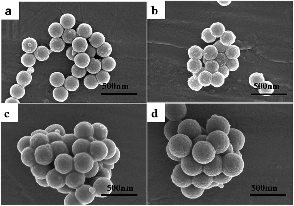 | ||
| Fig. 1 PS@SiO2 spheres prepared by coating uniform amorphous silica on different PS NPs: (a) 220 nm ± 5; (b) 250 nm ± 5; (c) 300 nm ± 5; (d) 340 nm ± 5. | ||
The shell thickness of SiO2 strongly depends on the concentrations of TEOS, and the shell thickness is increased with the concentration of TEOS. PS beads terminated with an –NH2 group could change their surface charge from negative into neutral (or slightly positively charged) and silica sols could easily be nucleated on the surface of each PS bead and eventually merge and grow into a thin shell characterized by uniform thickness.
FTIR spectra of the PS NPs and the ammonium treated PS are shown in Fig. 2a. The characteristic bands of PS could be observed in both of the samples: C–H stretch around 3000 cm−1, aromatic C–C stretch around 1470 cm−1, C–H out-of plane bend at 765 cm−1, and aromatic C–C out-of-plane bend at 700 cm−1. The characteristic absorption of the amino group at 3404 cm−1 indicates the existence of –NH2 in the ammonium treated sample.
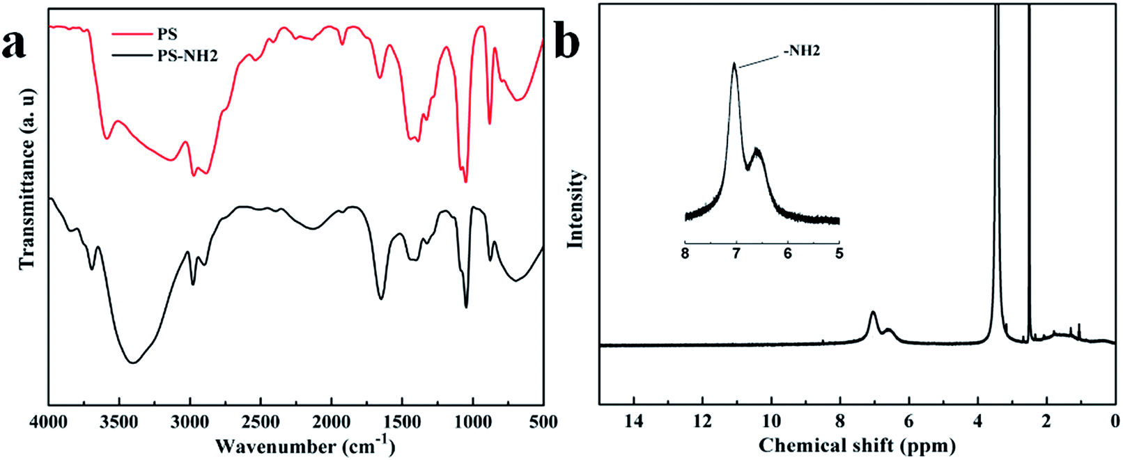 | ||
| Fig. 2 (a) Infrared spectra (FTIR) of PS NPs and the ammonium treated NPs. (b) 1H-NMR spectra of the –NH2 modified PS. | ||
1H-NMR was also used to confirm the existence of –NH2 on PS NPs. Fig. 2b shows the 1H-NMR spectra and the proton attached to the primary amine (–NH2) is observed at 7.2 ppm.
Fig. S3 (ESI†) shows the results of the electrophoretic measurement of pure PS beads and –NH2 terminated PS beads and the colloidal stability was apparent from these measurements. The decrease in electrophoretic mobility from −0.6914 to −0.2941 μm cm V−1 s−1 indicates the success of the –NH2 group anchored on the surface of the PS NPs. A change in the zeta potential of the particles was observed from approximately −33.3 mV for a bare PS surface to −14.17 mV. Thus, the –NH2 is successfully anchored on the surface of PS NPs.
The measured zeta potentials for the PS, PS@SiO2 NPs are approximately −33.3 mV and −31.48 mV, respectively, and the zeta potential is high enough for the suspension to keep stable for several hours. Fig. S4 (ESI†) shows the transmittance changes of the PS@SiO2 solution over time. The PS@SiO2 sample (Fig. S4a†) appeared very stable over 26 hours and the transmittance only changed a little (Fig. S4b†). Thus, the homogeneous PS@SiO2 spheres could be utilized to fabricate 3D PCs.
Fig. 3 displays the SEM image of large scale domains of PS@SiO2 crystalline arrays with dimensions of approximately 20 μm. The crystalline arrays are ordered 3D hexagonal close-packed structures, and both of the six-fold symmetry and high degree of crystalline order are reflected in the fast Fourier transform (FFT) spot pattern (shown in the insert of Fig. 2). Whereas peaks up to third orders are clearly present, some defects still exist in the crystalline arrays. The formation of defects may result from the evaporation of a water molecule and a hydroxyl group on the surface of PS@SiO2 spheres during self-assembly and the thermal treatment process.37
 | ||
| Fig. 3 SEM images of large scale domains of PS@SiO2 crystalline arrays with hexagonal close-packed structures. The insert in Fig. 3 is the FFT spot pattern of a single crystal domain. | ||
3.2. Air@C@SiO2 nanospheres
The TEM images of various core–shell particles prepared at different TEOS concentration are shown in Fig. 4. For example, the PS@SiO2 spheres with the core sizes of 180 nm, 200 nm, 240 nm and 290 nm are coated on silica shells with thicknesses of 20 nm, 25 nm, 30 nm and 25 nm in different TEOS concentrations, respectively. The particle size and shell thickness of the core–shell particles after calcination are listed in Table S2 (ESI†). | ||
| Fig. 4 The TEM images of various core–shell particles prepared at the same TEOS concentration. For example, the PS@SiO2 spheres with a core size of (a) 180 nm, (b) 200 nm, (c) 240 nm and (d) 290 nm were coated on silica shells with thicknesses of (a) 20 nm, (b) 25 nm, (c) 30 nm and (d) 25 nm, respectively, and were fabricated at the same TEOS concentration. | ||
The traditional way for fabricating PCs from hollow shells involves two steps: first, the formation of colloidal crystals of core–shell particles and this is followed by the removal of the organic core by corrosion or calcination. In this study, air@C@SiO2 core–shell spheres were obtained by calcining the PS@SiO2 PCs at 500 °C for 2 h in Ar, PCs of PS@SiO2 were calcined at 500 °C for 2 h in air have also been prepared for comparison. PS cores were burned away when calcined in air whereas part of the carbon still remained inside the shell as an absorbent layer when calcination was carried out in Ar. Thus, bi-layer core–shell nanospheres composed of a thin carbon layer in the interior of the silica shell were generated.
Energy-dispersive X-ray spectroscopy (EDX) element mapping of air@C@SiO2 NPs, shown in Fig. 5, was used to show the space distribution of Si, O, and C elements. The intense Si and O signals throughout the shells suggest that the SiO2 shell is homogeneous. The enhanced C signals in the internal edge of SiO2 shell show that the carbon black originated from the PS NPs.
 | ||
| Fig. 5 EDX element mapping of the identical NPs of air@C@SiO2 and air@SiO2. | ||
3.3. Optical properties of PS, PS@SiO2 and hollow SiO2 photonic crystals
The microscopic images of PCs structurally colored films and the corresponding reflective spectra are shown in Fig. 6. The peak positions shift to a longer wavelength as the shell thickness increased and the shift trend of the reflection spectra agrees very well with other work reported in the literature.25 The changes in reflection peak positions result from the variation of inter-planar spacing and effective refractive index. The Bragg law is given by eqn (1):34,46,47|
mλpeak = 2dhkl[neff2 − sin2θ]
| (1) |
 | (2) |
| neff = [nsphere2f + nair2(1 − f)]1/2 | (3) |
 | ||
| Fig. 6 Microscopic image reflective model: (a1 and a2) colloidal crystal film of PS180, PS@SiO2 220 nm; (b1 and b2) PS200, PS@SiO2 250 nm; (c1–c3) PS240, PS@SiO2 260 nm, PS@SiO2 300 nm; (d1–d3) PS290, PS@SiO2 310 nm, PS@SiO2 340 nm; (A–D) are the corresponding reflective spectra of PCs of PS and PS@SiO2 spheres at normal incidence. | ||
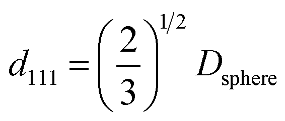
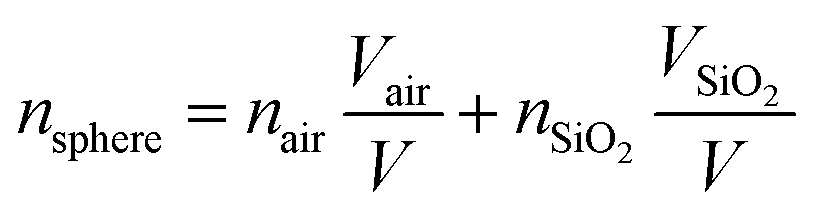
For the PS@SiO2 spheres, nsphere can be calculated by using eqn (4):
 | (4) |
Thus, for PS NPs:
| λ = 2.382Dsphere |
| nPS@SiO2 = 1.46 + 0.13 × (r/R)3 |
The reflection peak positions of PCs assembled by PS and PS@SiO2 NPs shown in Fig. 7 indicate that some discrepancies exist between the calculated and measured values, and the previously mentioned difference could be resolved by taking the defects of the PCs into account. Fig. 3 shows that some defects still exist in the PCs although the ordered packing of the PCs is characterized by hexagonal close-packed arrays. Thus, the volume of the sphere is partly replaced by the solvent or air and the effective refractive index of the PCs is lower than 0.74.
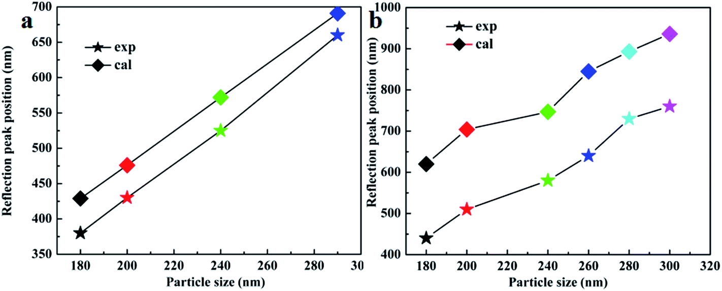 | ||
| Fig. 7 The calculated (cal) and experimental (exp) reflection peak positions of (a) PS and (b) PS@SiO2 PCs. | ||
Fig. 8 shows the variation tendency of reflection peak positions for different PC films, and the stop band of the hollow SiO2 PCs have an obvious blue-shift because of the decrease of effective refractive index (neff) and particle size during calcination when compared with PCs assembled by PS and PS@SiO2. In order to theoretically calculate the Bragg diffraction peak, eqn (4) should be modified by using eqn (5):
 | (5) |
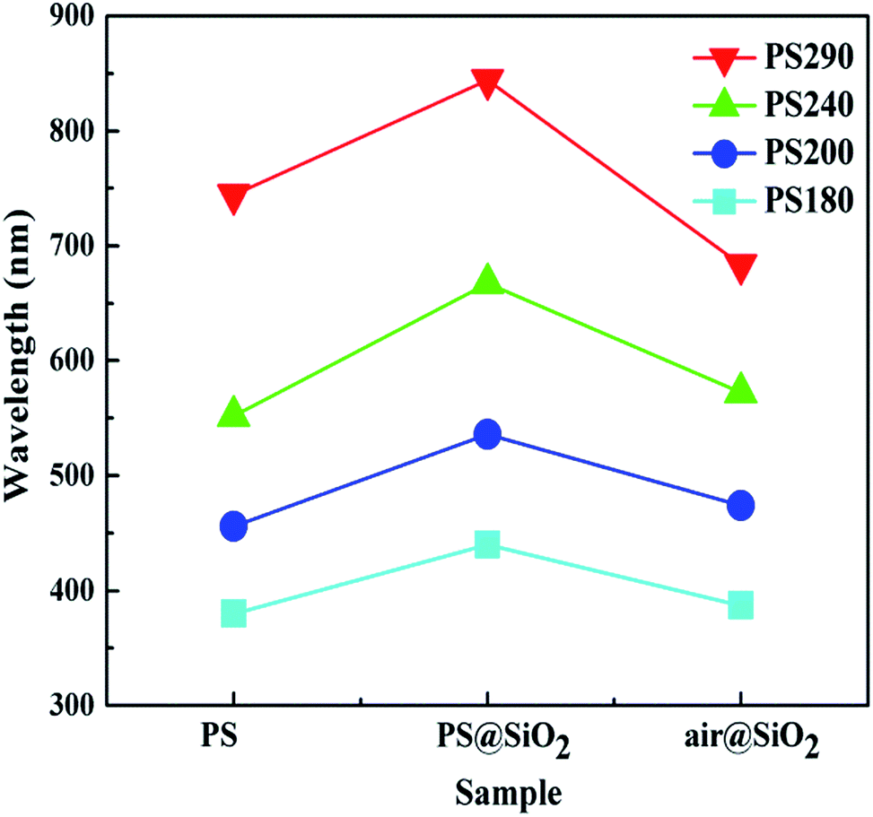 | ||
| Fig. 8 Tendency of reflection peak positions of photonic crystal films. | ||
3.4. Photonic crystal of air@C@SiO2 with enhanced color saturation
When the calcination process was carried out in air, the sample showed an extremely weak appearance of color. However, the color saturation was significantly enhanced when the calcination process was carried out at 500 °C in argon. Fig. 9 shows the images of colored films and PCs domains assembled by air@C@SiO2 NPs. Because the absorbing materials originated from the carbonization of PS this causes the multiple scattering of lights to be reduced considerably whereas the reflection intensity caused by coherent scattering was only slightly decreased. In this way, the color saturation could be enhanced significantly without disturbing the PCs arrays. In addition, PCs calcined in air and Ar have the same color appearance, indicating that the black material originated from PS just absorbs the incoherent scattering light and makes no contribution to the structural colors. Interestingly, the colorful PCs samples in powder form still possess brilliant structural colors (shown in Fig. 10), which could be used as physical pigments. | ||
| Fig. 9 The optical images of colored films and photonic crystal domains of air@C@SiO2 nanospheres. (a and a′) Air@C@SiO2 220 nm; (b and b′) air@C@SiO2 250 nm; (c and c′) air@C@SiO2 300 nm; (d and d′) air@C@SiO2 340 nm. The core size from (a–d) is 180 nm, 200 nm, 240 nm; 290 nm, separately. | ||
 | ||
| Fig. 10 Photonic crystal domains of PS@SiO2 NPs calcination in different environments. (A–D) Calcination under Ar protection. (A′–D′) Calcination in air. (A) PS@SiO2 220 nm; (B) PS@SiO2 250 nm; (C) PS@SiO2 300 nm; PS@SiO2 340 nm. The core size from (A–D) is 180 nm, 200 nm, 240 nm; 290 nm, respectively. | ||
4. Conclusion
PS@SiO2 core–shell nanoparticles with shell thickness ranging from 20 nm to 30 nm by coating uniform shells of amorphous silica on PS beads which were terminated with –NH2 groups were prepared, and the particle sizes could be easily controlled by manipulating the hydrolysis and condensation of the TEOS precursor. 3D PCs of PS and PS@SiO2 were fabricated via vertical deposition. The PS cores were burned away when calcined in air whereas part of the carbon still remained inside the shell when calcination was at 500 °C in Ar, and bi-layered nanospheres composed of a carbon black layer in the interior of the silica shell were generated. Most importantly, the visibility of these hollow SiO2 PCs was significantly enhanced without disturbing the PCs arrays when calcination was carried out in Ar, and the black materials originated from PS just absorb incoherent scattering light and make no contribution to the colored appearance. This method will be widely useful for improving the color saturation without disturbing the PCs. Furthermore, hollow SiO2 photonic crystals with a high color saturation will enrich the application of core–shell NPs in many fields such as bionic colors, paint, cosmetics, and photonic papers.Acknowledgements
This work was supported by the National Natural Science Foundation of China (51472153, 51232008).References
- S. G. Johnson, J. D. Joannopoulos, J. N. Winn and R. D. Meade, Photonic Crystals: Molding the Flow of Light, 2011 Search PubMed.
- O. Painter, R. Lee, A. Scherer, A. Yariv, J. O'Brien, P. Dapkus and I. Kim, Science, 1999, 284, 1819–1821 CrossRef CAS PubMed.
- H. Altug and J. Vučković, Appl. Phys. Lett., 2005, 86, 111102 CrossRef.
- Y. H. Liu, X. Y. Hu, D. X. Zhang, B. Y. Cheng, D. Z. Zhang and Q. B. Meng, Appl. Phys. Lett., 2005, 86, 151102 CrossRef.
- M. Scalora, J. P. Dowling, C. M. Bowden and M. J. Bloemer, Phys. Rev. Lett., 1994, 73, 1368 CrossRef CAS PubMed.
- H. T. Yang and P. Jiang, Langmuir, 2010, 26, 13173–13182 CrossRef CAS PubMed.
- Q. S. Jiang, C. Li, S. G. Shi, D. G. Zhao, L. Xiong, H. L. Wei and L. Yi, J. Non-Cryst. Solids, 2012, 358, 1611–1616 CrossRef CAS.
- S. K. Yang, W. P. Cai, L. C. Kong and Y. Lei, Adv. Funct. Mater., 2010, 20, 2527–2533 CrossRef CAS.
- S. K. Yang, M. I. Lapsley, B. Q. Cao, C. L. Zhao, Y. H. Zhao, Q. Z. Hao, B. Kiraly, J. Scott, W. Z. Li and L. Wang, Adv. Funct. Mater., 2013, 23, 720–730 CrossRef CAS.
- K. Yamashita, Y. Yoshioka, K. Higashisaka, K. Mimura, Y. Morishita, M. Nozaki, T. Yoshida, T. Ogura, H. Nabeshi and K. Nagano, Nat. Nanotechnol., 2011, 6, 321–328 CrossRef CAS PubMed.
- Y. Takeoka, S. Yoshioka, A. Takano, S. Arai, K. Nueangnoraj, H. Nishihara, M. Teshima, Y. Ohtsuka and T. Seki, Angew. Chem., Int. Ed., 2013, 52, 7261–7265 CrossRef CAS PubMed.
- S. John, Phys. Rev. Lett., 1987, 58, 2486 CrossRef CAS PubMed.
- E. Yablonovitch, Phys. Rev. Lett., 1987, 58, 2059 CrossRef CAS PubMed.
- M. Srinivasarao, Chem. Rev., 1999, 99, 1935–1962 CrossRef CAS PubMed.
- Y. Gotoh, H. Suzuki, N. Kumano, T. Seki, K. Katagiri and Y. Takeoka, New J. Chem., 2012, 36, 2171–2175 RSC.
- Y. Takeoka, M. Honda, T. Seki, M. Ishii and H. Nakamura, ACS Appl. Mater. Interfaces, 2009, 1, 982–986 CAS.
- V. L. Colvin, MRS Bull., 2001, 26, 637–641 CrossRef CAS.
- X. L. Xu and S. A. Asher, J. Am. Chem. Soc., 2004, 126, 7940–7945 CrossRef CAS PubMed.
- L. Wang and S. A. Asher, Chem. Mater., 2009, 21, 4608–4613 CrossRef CAS PubMed.
- H. Nakamura and M. Ishii, J. Appl. Polym. Sci., 2007, 103, 2364–2368 CrossRef CAS.
- Y. Lu, Y. D. Yin, Z. Y. Li and Y. N. Xia, Nano Lett., 2002, 2, 785–788 CrossRef CAS.
- F. Caruso, M. Spasova, V. Salgueiriño-Maceira and L. Liz-Marzán, Adv. Mater., 2001, 13, 1090–1094 CrossRef CAS.
- Y. N. Xia, B. Gates, Y. D. Yin and Y. Lu, Adv. Mater., 2000, 12, 693–713 CrossRef CAS.
- K. P. Velikov, A. Moroz and A. van Blaaderen, Appl. Phys. Lett., 2002, 80, 49–51 CrossRef CAS.
- Z. Y. Zhong, Y. D. Yin, B. Gates and Y. N. Xia, Adv. Mater., 2000, 12, 206–209 CrossRef CAS.
- A. Guerrero-Martínez, J. Pérez-Juste and L. M. Liz-Marzán, Adv. Mater., 2010, 22, 1182–1195 CrossRef PubMed.
- H. Zou, S. Wu and J. Shen, Chem. Rev., 2008, 108, 3893–3957 CrossRef CAS PubMed.
- Y. J. Wong, L. Zhu, W. S. Teo, Y. W. Tan, Y. Yang, C. Wang and H. Chen, J. Am. Chem. Soc., 2011, 133, 11422–11425 CrossRef CAS PubMed.
- F. Mahtab, Y. Yu, J. W. Lam, J. Liu, B. Zhang, P. Lu, X. Zhang and B. Z. Tang, Adv. Funct. Mater., 2011, 21, 1733–1740 CrossRef CAS.
- L. H. Jing, C. H. Yang, R. R. Qiao, M. Niu, M. H. Du, D. Y. Wang and M. Y. Gao, Chem. Mater., 2009, 22, 420–427 CrossRef.
- B. Tan and S. E. Rankin, Langmuir, 2005, 21, 8180–8187 CrossRef CAS PubMed.
- W. G. Leng, M. Chen, S. X. Zhou and L. M. Wu, Langmuir, 2010, 26, 14271–14275 CrossRef CAS PubMed.
- W. Stöber, A. Fink and E. Bohn, J. Colloid Interface Sci., 1968, 26, 62–69 CrossRef.
- Y. Lu, J. McLellan and Y. Xia, Langmuir, 2004, 20, 3464–3470 CrossRef CAS PubMed.
- T.-S. Deng and F. Marlow, Chem. Mater., 2012, 24, 536–542 CrossRef CAS.
- Q. S. Jiang, J. Zhong, X. Hu, F. F. Song, K. Ren, H. L. Wei and L. Yi, Colloids Surf., A, 2012, 415, 202–208 CrossRef CAS.
- H. L. Li, W. T. Dong, H.-J. Bongard and F. Marlow, J. Phys. Chem. B, 2005, 109, 9939–9945 CrossRef CAS PubMed.
- H. Míguez, F. Meseguer, C. López, Á. Blanco, J. S. Moya, J. Requena, A. Mifsud and V. Fornés, Adv. Mater., 1998, 10, 480–483 CrossRef.
- Z. Z. Gu, H. Uetsuka, K. Takahashi, R. Nakajima, H. Onishi, A. Fujishima and O. Sato, Angew. Chem., Int. Ed., 2003, 42, 894–897 CrossRef CAS PubMed.
- S. Yoshioka and Y. Takeoka, ChemPhysChem, 2014, 15, 2209–2215 CrossRef CAS PubMed.
- J. D. Forster, H. Noh, S. F. Liew, V. Saranathan, C. F. Schreck, L. Yang, J. G. Park, R. O. Prum, S. G. Mochrie and C. S. O'Hern, Adv. Mater., 2010, 22, 2939–2944 CrossRef CAS PubMed.
- W. T. Wang, B. T. Tang, W. Ma, J. Zhang, B. Z. Ju and S. F. Zhang, J. Opt. Soc. Am. A, 2015, 32, 1109–1117 CrossRef CAS PubMed.
- C. I. Aguirre, E. Reguera and A. Stein, ACS Appl. Mater. Interfaces, 2010, 2, 3257–3262 CAS.
- X. Du and J. H. He, J. Appl. Polym. Sci., 2008, 108, 1755–1760 CrossRef CAS.
- I. Tissot, J. Reymond, F. Lefebvre and E. Bourgeat-Lami, Chem. Mater., 2002, 14, 1325–1331 CrossRef CAS.
- Z. Chen, P. Zhan, Z. Wang, J. Zhang, W. Zhang, N. Ming, C. T. Chan and P. Sheng, Adv. Mater., 2004, 16, 417–422 CrossRef CAS.
- H. Nakamura, M. Ishii, A. Tsukigase, M. Harada and H. Nakano, Langmuir, 2006, 22, 1268–1272 CrossRef CAS PubMed.
Footnote |
| † Electronic supplementary information (ESI) available. See DOI: 10.1039/c5ra25680a |
| This journal is © The Royal Society of Chemistry 2016 |