 Open Access Article
Creative Commons Attribution 3.0 Unported Licence
Reproducible shape control of single-crystal SnO micro particles†
Mai Thanh Nguyen,
Hiroaki Shirai,
Chondanai Tiankanon‡
,
Hiroki Tsukamoto,
Yohei Ishida and
Tetsu Yonezawa*
Division of Materials Science and Engineering, Faculty of Engineering, Hokkaido University, Kita 13 Nishi 8, Sapporo, Hokkaido 060-8628, Japan. E-mail: tetsu@eng.hokudai.ac.jp
First published on 7th March 2016
Abstract
A straightforward method for synthesizing single-crystalline SnO micro particles in an organic medium using tin acetylacetonate as the precursor and oleylamine as the capping ligand is proposed. For the first time, well-defined four-petal starfish-like SnO sheets were obtained in the organic medium. In addition, the shape of the particles could be reproducibly tuned such that their structures varied from cubes to squares and then to starfish-like sheets by simply changing the concentration of oleylamine. The underlying mechanism of this process was found to be closely related to the interaction of the stabilizing agent with the SnO crystal planes. Changing the concentration of the stabilizing agent could modify this interaction, leading to the preferential growth of certain crystal planes of SnO particles which determined the particle shape. This synthesis approach is advantageous in terms of allowing control over the particle shape as well as for its simplicity and short reaction time. Our results yield crucial insights regarding the shape evolution of SnO particles.
Introduction
Tin monoxide (SnO) belongs to a class of materials that show considerable promise for use in rechargeable Li ion battery electrodes,1–3 as a native p-type conducting material,4,5 and as catalysts.6,7 Additionally, when exhibiting the intermediate oxidation state SnO can be used to prepare SnO2, which is also highly attractive as a material for energy conversion and storage devices,8,9 and gas sensors,10 as well as for n-type transparent conductive oxides.9,11 However, the fact that SnO can transform into the more thermodynamically stable Sn and SnO2 phases, making it a challenge to prepare stable single-phase crystalline SnO materials.12 Only in some cases under thermal vapor deposition conditions or performing long reaction time of a hydrothermal synthesis, it is possible to obtain single crystalline SnO.13,14 Therefore, a new process for synthesizing single-crystalline SnO using a simpler solution-based approach would be highly desirable.For the applications of tin oxides, controlling the morphology and structure of the particles is the key factor, as it significantly influences the outcome properties of the resulting materials12,15 including the capacity and cycling stability,1–3,8,9 gas sensing and catalytic activities,9,10,12,16 optical and electrical properties.9,11,17 In term of particle morphologies, the vacuum techniques13,18,19 often result in diskette SnO particles while the solution method is more feasible to synthesize SnO with different morphologies such as truncate pyramids,14 square sheets,14,20–23 crosses,24 meshes,25 and flower like structure.26,27 However, these solution syntheses mainly rely on the hydrothermal reaction in water-based media in which tin salts undergo the hydrolysis under alkaline condition then decomposition at elevated temperature and pressure to form SnO. Despite high energy consumption and the complex nature of the process, which involves the management of various parameters and a long reaction time, SnO particles of a single morphology were obtained in each synthesis method. It is likely that the extreme conditions result in only one thermodynamic stable form, with being less possibility of kinetically surfactant-supported particle growth towards other types of morphologies. This has limited the systematic study and control of the morphology-dependent properties of SnO particles.
On the other hand, we noticed that the synthesis in organic media under milder conditions while employing capping ligands can help modify particle morphology and structure without having to control over the pH or pressure.15 However, in a previous study on the synthesis of SnO in an organic medium,27 water was still added to hydrolyze SnCl2, giving assemblies of polycrystalline SnO nanoparticles. So far, the synthesis of SnO in organic media has not been investigated widely and the tunable morphologies and the formation mechanism of SnO have not been fully achieved.
In this study, we developed a facile synthesis strategy based on the reaction of tin(II) acetylacetonate (Sn(acac)2) in the presence of a capping ligand in an organic medium to allow for the reproducible, simple and easy control of the structure and morphology of SnO particles. Sn(acac)2 was selected as the precursor instead of inorganic tin salts because metal acetylacetonates are soluble in organic solvents and decompose readily to form metal oxides at relatively low temperatures.28,29 By using the corresponding metal acetylacetonates, nanoparticles of various oxides, such as Fe3O4, CoFe2O4, MnFe2O4, CoO, Co3O4, MnO, Mn3O4, NiO, and ZnO, to name a few, with high uniformity, good dispersibility and controllable morphologies have been prepared previously.30–35 Of the various stabilizing agents available, we chose oleylamine, since it has been shown to function not only as a mild complexing agent for metal precursors to be decomposed/reduced in a controlled way but also as a molecular capping ligand to aid the shape evolution of various nanoparticle systems.36 The reaction medium produced by adding oleylamine to octadecene is compatible with the metal source, Sn(acac)2, and allows for varying its composition systematically; hence it is promising and suitable for the controlling formation and shape evolution of SnO particles while using Sn(acac)2 as precursor. Using this simple approach, neither water nor an alkali was added, single-crystal SnO micro particles with tailorable and well-defined shapes were obtained reproducibly. Surprisingly, the shapes of the SnO micro particles were only a function of the concentration of oleylamine. This novel synthesis approach is advantageous in that it results in the robust nucleation and selected growth of particles and allows for the easy control of the shapes and size of the SnO particles. The single-crystal nature of the obtained SnO micro particles, their chemical states, shape formation mechanism, and the preparation of SnO2 from SnO particles of similar shapes were also investigated.
Experimental
Chemicals
Tin acetylacetonate (Sn(acac)2, purity 99.9%), oleylamine (OAM, assay 70%) and 1-octadecene (OD, assay 90%) were purchased from Sigma Aldrich. OAM was distilled and stored under dry conditions with an activated molecular sieve (type 3A), while other chemicals were used as received. Ethanol and hexane were used as received.Synthesis of SnO micro particles
A total of 27.5 mL of a solution of OAM and OD (the volume percentages of OAM was 0–100%) was added into a round-bottomed three-neck flask without any scratches inside. The solution was purged with nitrogen for 1 h at room temperature and again at 120 °C in order to remove oxygen and any volatile molecules. All procedures were performed under nitrogen. Next, 1.52 mmol of Sn(acac)2 was added to the solution. The reaction solution was then heated to 200 °C at a heating rate of 3 °C min−1 using an oil bath. The reaction was allowed to occur for 20 min at 200 °C under vigorous stirring. The flask was then taken out from the oil bath and cooled to room temperature using a blower. An ethanol/hexane mixture (1/1 v/v) was added to the reaction solution, and the resulting particles were separated from the matrix by centrifugation at 3000 rpm (×800g). The purification procedure was repeated five times. Finally, the obtained particles were collected and stored in a nitrogen atmosphere for characterization. After the first centrifugation process, no unreacted Sn precursor molecules in the supernatant were detected by X-ray fluorescence (XRF, JEOL JSX-3100RII Element Analyzer) spectroscopy; this suggested that the conversion of tin precursor had been complete.For the time-dependent particle growth, 36 vol% OAM was used in the synthesis. When the reaction solution reached 200 °C, 3 mL reaction solution was sampled using a syringe and needle after various reaction time (0–20 min), then immediately injected into 12 mL ethanol (precool in a cool bath at −5 °C) to quench the reaction. The obtained particles were then purified as described above.
In some cases, the obtained SnO particles were annealed in air using a furnace (Full-tech, FT101-FM) at 370, 500 and 700 °C for 2 h; the ramp rate used was 20 °C min−1.
Characterizations
Powder X-ray diffraction (XRD) measurements (Rigaku MiniFlex II with a Cu Kα, 30 kV 15 mA) were performed on dry powders of the resulting particles immediately after the purification. Scanning electron microscope (SEM) observations were performed on a JEOL JSM-6701F field-emission SEM at an acceleration voltage of 15 kV and emission current of 10 μA. The morphology and selected area electron diffraction (SAED) patterns of the resulting particles were determined using transmission electron microscope (TEM) systems (JEOL JEM-2100F and JEM-2010) at an acceleration voltage of 200 kV. Focused ion beam (FIB) was performed using a JEOL JIB-4600F/HKD multi beam system. The sample for FIB was prepared by first pasting the synthesized particles on a piece of conductive carbon tape and then coating particles with a layer of tungsten prior to cutting them using the FIB along the top-down direction of the particles (normal to the substrate). Cs-corrected scanning TEM (STEM) and EDS mapping images were collected using an FEI Titan3 G2-60-300 (300 kV).The chemical state of the particles near their surface area was analysed with a JEOL JPS-9200 X-ray photoelectron spectroscopy (XPS) system using X-ray radiation from a Mg Kα anode (1253.6 eV) and a JEOL JAMP-9500F field emission Auger (AES) microprobe with a probe current of 70 nA using the M3 analysis channel. For the XPS and AES measurements, dispersions of the particles in hexane were dropped onto cleaned Si wafers. Si 2p3/2 (at 99.2 eV) was used as the reference for the charging effect correction of the narrow-scan Sn 3d XPS spectra. For AES measurements, all the parameters, including the sample tilt angle (30° from the direction of the incident electron beam), probe current, and analysis channel were the same as those used to obtain the standard spectra of Sn, SnO and SnO2. The chemical states of samples were analysed by curve fitting the obtained spectra using the standard spectra of Sn in Sn, SnO and SnO2.
Fourier transformation infrared (FT-IR) spectra were collected using a Jasco FT/IR-4600 Spectrometer in range of 400–4000 cm−1 for purified SnO particles (synthesized using 36 vol% OAM) and pure OAM.
The optical absorption spectra of the samples were collected using a Jasco V-670 spectrophotometer.
Results and discussion
Crystal structure and morphology of SnO micro particles formed using OAM in various concentrations
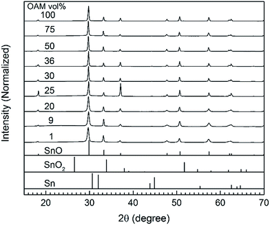
The crystal structures of the as-synthesized SnO micro particles were characterized using X-ray diffraction (Fig. 1). In the absence of OAM, the obtained powder was yellowish orange and did not exhibit a crystalline structure (Fig. S1A†). The amorphous particles were of 100 nm in size and shaped like thin circles and thus different from all other particles synthesized with OAM (Fig. S1B and C†). When OAM was used (1 to 100 vol% OAM), the resulting particles were crystalline SnO with a tetragonal structure. Moreover, no signals from any other phases such as metallic Sn, SnO2, or tin oxide hydroxides were observed. The presence of OAM was thought to be necessary to form an intermediate complex/compound with Sn(acac)2 which could decompose under the reaction condition (200 °C, 20 min) to form crystalline SnO particles, as also reported when SnCl2 was used as a metal source.27 The average crystalline size of particles calculated from line broadening of the XRD peaks (Table S1†) indicated that the average crystalline size is in range of 116–140 nm for all samples synthesized using OAM from 25 vol%. In this size range, the crystalline size does not directly indicate the real particle size and the obtained results reach the limit of the laboratory XRD equipment. The particles synthesized using less OAM vol% show smaller crystallite sizes 50–60 nm, but noticeable high strain broadening (0.35–0.44%). Such high strain also hinders the crystallite size verified based on the line broadening (normally 1% strain limits the maximum crystallite size to as small as ∼30 nm). The results indicated that the particles are considerable large for the crystallite size analysis based on XRD, suggesting long range order of the crystal structures.The structures and morphologies of the SnO particles synthesized using OAM in different concentrations were observed using FE-SEM. Fig. 2 shows side-view images of the synthesized SnO particles and their over-view SEM images are collected in Fig. S2.†
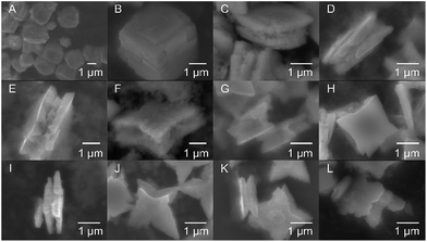 | ||
| Fig. 2 SEM side-view images of the SnO particles obtained using OAM in different concentrations: (A) 1%, (B) 9%, (C and D) 20%, (E and F) 25%, (G and H) 30%, (I and J) 50%, (K) 75%, and (L) 100%. | ||
The particle morphology significantly varied with the volume ratio of OAM. Cubic particles with a size of 2–3 μm were obtained for the lowest OAM concentrations (1–9 vol%). The cracks observed in these particles are thought to be induced by the strain generated during the growth of the particles. An increase in OAM concentration to 20 vol% resulted in the formation of square sheets of 2–3 μm in size. A further increase in the OAM concentration (25 to 75 vol%) led to the growth of sheets with starfish-like shape. Finally, when only OAM was used as the solvent and stabilizing reagent, starfish-like structures with smoother petals were formed. It should be notable that these synthesized particles had surface diagonals of similar lengths, which were also similar to those of the square sheets; however, the particle thickness decreased with an increase in the amount of OAM used. The thickness of the SnO particles decreased from 1800–1500 nm for the cubic particles (9 vol% OAM) to 900–1000 nm for the square sheets (20 vol% OAM) and 700–500 nm for the starfish-like particles (25–100 vol% OAM). These results indicated that the particle shape was closely related to the concentration of OAM during the synthesis process. A summary of the structure and morphology of SnO particles is given in Table 1.
| OAM (vol%) | Structure | Morphology | Thickness [nm] |
|---|---|---|---|
| 0 | Amorphous | Spherical shape | 50–100 |
| 1–9 | Crystalline | Cube | 1500–1800 |
| 9–20 | Crystalline | Square sheet | 900–1000 |
| 20–25 | Crystalline | Square to starfish-like sheet | 700–900 |
| 25–100 | Crystalline | Starfish-like sheet | 500–700 |
A closer look at the structures shows that the square sheets and the starfish-like particles consisted of sheets that were stuck together. Further, a number of double-stacked sheets can also be seen (Fig. 2C–L). Especially, for starfish-like particle, each stacked sheet is composed of a number of thin SnO layers (Fig. 2E–L, also see Fig. 4). In addition, a concave surface between the double-stacked sheets is also observed (Fig. 2C–L), most clearly seen in case of starfish-like sheets such as Fig. 2G, J, and K.
The synthesis method was also able to tune the size of the particles while allowing their shape being maintained. An example of this is shown in Fig. S3,† where the particle size was varied as a function of the amount of Sn(acac)2 used with the constant concentration (9 vol%) of OAM.
SAED patterns and HR-TEM images
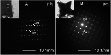
The morphology of the synthesized particles was correlated to the crystal structure and growth mechanism. The representative SAED patterns for the cubic and starfish-like particles, which were obtained using 9 and 36 vol% OAM, respectively (Fig. 3). In the case of the cubic SnO particles, the particle thickness was several micrometers (Fig. 2). This was too high to be able to obtain their SAED pattern using TEM. Therefore, FIB milling was used to cut one such particle into a thin (<100 nm) film in the direction normal to its surface. An SEM image of the micro particle (top-down surface) before the FIB treatment and a TEM image of the thin film after FIB etching are shown in Fig. S4.†The SAED patterns exhibited that the particles were single crystals in the both cases. The SAED pattern (Fig. 3A) of the cubic particle suggests the presence of a (001) crystal plane as the particle surface and (110) crystal planes as the side surfaces of the micro particle. On the other hand, in the case of the starfish-like particles (Fig. 2E–L and 3B), the surface plane was normal to the [001] direction, while the [110] and [100] directed to the side edge and the tip, respectively. These results suggested that, in the both cases, the surfaces of particles were normal to [001] direction, the [110] direction was towards the lateral surfaces and the [100] direction was along the intersections of these lateral surfaces.
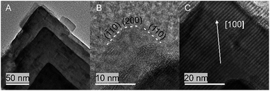
A detailed HRTEM examination of the structure of the starfish-like particles (Fig. 4) confirmed that the [200] direction was the preferred growth direction (towards the tip of the particle) in the case of these particles. The images showed that they comprised multiple thin SnO layers with the same crystal structure and orientation. The epitaxial growth of these layer during particle formation accounts for the obtained morphology.
Time dependent shape formation of starfish-like SnO particles
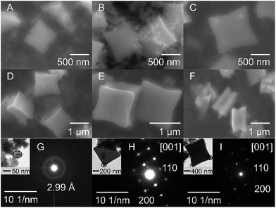
The time-dependent shape evolution of starfish-like SnO particles was investigated (Fig. 5) using 36 vol% OAM in the synthesis as a case study. We noted that near 200 °C (∼195–198 °C) the colour of the reaction solution was still yellow-orange which turned to grey at 200 °C and soon later became black, indicating the formation of SnO particles. When temperature reached 200 °C (0 min reaction), particles of 500–700 nm (side dimension) shaped nearly square (Fig. 5A and inset of 5H) were obtained beside a large number of small particles, about several nm of the diameter (Fig. 5A, insets of 5G). Increase in reaction time (1, 3, 6 min), the distorted square particles grew in their size (∼800–900 nm, 1000–1200, 1200–1400 nm, respectively) and their shape towards starfish-like (Fig. 5B–D). Particle growth became mature after 20 min reaction with all feature of the starfish-like particles obtained in the standard reactions (Fig. 5E–F). The distorted square and starfish-like particles exhibited SAED patterns of single crystalline SnO (Fig. 5H–I). The aggregation of small particles (several nm) observed at 0 min reaction gave a ring pattern in electron diffraction, which reflected small size nature of the particles in the aggregate. The d-spacing 2.99 Å reveals either the primary (101) planes in SnO (2.9890 Å) or (202) planes in Sn6O4(OH)4 (2.9889 Å). The XRD pattern (Fig. S5†) of sample obtained when reaction temperature reached 200 °C (0 min) suggested that SnO was formed as the main phase, and Sn6O4(OH)4 was found as minor phase. After 1 min reaction, the signals from Sn6O4(OH)4 were not detected and only signals from SnO presented in the XRD pattern (Fig. S5†). It is noticeable that the small particles still exist after 1 min reaction as shown in SEM and TEM images (Fig. 5), and just become less for longer reaction time. Based on these results, we thought that tin oxide hydroxide found at 0 min reaction is probably a result of the reaction between metal precursor and water in the solvent during purification process; and the small particles are SnO, being consumed for the growth of the starfish-like SnO particles.FT-IR spectrum of SnO particles
FT-IR spectrum (Fig. S6†) and the detailed peak assignment and interpretation (Table S2†) of the purified SnO particles are shown in comparison to those of pure OAM. The spectrum of SnO reveals the characteristic vibration mode from Sn–O at 499 cm−1.37 Moreover, the characteristic modes of OAM are clearly seen: δ(NH2) (1550–1620 cm−1 and 790–810 cm−1), δ(C–N) (1060–1090 cm−1), ν(![[double bond, length as m-dash]](https://www.rsc.org/images/entities/char_e001.gif) C–H) (3003–3006 cm−1), νas(C–H) and νs(C–H) (2920 and 2851 cm−1), ν(C
C–H) (3003–3006 cm−1), νas(C–H) and νs(C–H) (2920 and 2851 cm−1), ν(C![[double bond, length as m-dash]](https://www.rsc.org/images/entities/char_e001.gif) C) (1640–1660 cm−1), δ(CH3) (1485–1405 cm−1).38 Some bands from SnO sample (bending modes of C–N and –NH2, and stretching mode of –NH2) show lower intensity and more broadened than that of pure OAM, but in general the characteristic modes of OAM from the SnO particles present at identical positions with those of pure OAM. This suggests that OAM molecules are absorbed on the surface of the SnO particles.
C) (1640–1660 cm−1), δ(CH3) (1485–1405 cm−1).38 Some bands from SnO sample (bending modes of C–N and –NH2, and stretching mode of –NH2) show lower intensity and more broadened than that of pure OAM, but in general the characteristic modes of OAM from the SnO particles present at identical positions with those of pure OAM. This suggests that OAM molecules are absorbed on the surface of the SnO particles.
Proposed shape formation mechanism
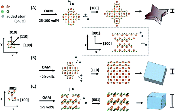
Using thermal vapour deposition method in the absence of capping agent, Dai et al. suggested that the initial growth along [100] direction was slightly faster than that along the [110] direction, giving small sized SnO diskettes an octagonal surface with long and short sides and larger SnO ones a circle contour (to lower the surface energy).13 Moving to a solution synthesis using hydrothermal reaction without surfactants, based on the fact that changing the reaction temperature could change the surface shape of single crystal SnO plates, the authors proposed that the shapes of particles were governed by the crystal structure and surface energy,14 this is similar to the above report. On the other hand, under sonication aided solution synthesis, previous study indicated that the use of different surfactants could change the growth rate of the (110) and (100) crystal planes to transform the basal surfaces of SnO particles from square to circle and again to square shapes with either (110) or (100) as the side planes.39 In the present study, various anisotropic shapes of SnO particles formed with varying OAM vol% under constant temperature reveals the role of OAM in directing the shape formation of the particle, possibly via control of the kinetic growth process of (100), (110) and (001) planes. According to the SAED, HR-TEM, and time-dependent shape growth results described above, the formation of particles of various shapes, as shown in Fig. 6, was owing to the preferential crystal growth along different directions induced by the concentration of OAM. According to these results we propose that OAM plays an important role in determining the preferential growth direction and the shape of SnO during particle formation and growth.The form transition from cube to square and to starfish-like sheets was induced by the increase of OAM concentration in the preparation solution (Table 1). As the OAM concentration was increased, first cubes and then square sheets were formed, suggesting that the basal (001) surface was stabilized by amines, leading to a decrease in the particle thickness.
The use of a high concentration of OAM (25–100 vol%, Fig. 6A) during the synthesis process induced relatively preferential growth along the [100] direction in SnO of tetragonal structure, leading to the four star-shaped petals, that is starfish-like sheets. Their thickness (the (001) plane was considered the surface plane) decreased with the increase in OAM concentration. Thus, the particles transformed into starfish-like particles with a lower thickness. When a smaller amount of OAM was used (∼20 vol%), there was no significant difference in the growth rates along the [110] and [100] directions (Fig. 6B). Finally, uniform growth along the [110] direction and somewhat restricted growth along the [001] direction were the main reason for the formation of the square sheets (Fig. 6B). When a very small amount of OAM (from 9 vol% or less) was used, it probably had a negligible effect on suppressing the crystal growth in the [001] and [110] directions (Fig. 6C). As a result, cubic particles were formed, and their surfaces were the most stable crystal planes ((001) and (110) planes). It is also known that (001) and (110) planes of SnO have the lowest surface energy.40
Moreover, it is interesting that, in the magnified side-view images of the particles prepared with OAM concentration of 20 vol% (square sheets, Fig. 2C and D), especially from 25 vol% OAM (starfish-like particle, Fig. 2E–L), particles clearly appeared to comprise a set of double-stacked sheet with a concave surface between the double-stacked sheet and each sheet consisted of multiple thin layers (see Fig. 4). The formation of the similar double-stacked sheet fashion (called “solid wheel with a drop centre rim”) for single crystalline SnO diskettes was also reported using thermal vapour deposition method, even though the formation mechanism was not clearly understood.13 The formation of this sheet stacking structure with an inner concave surface could be related also to the growth process, whereas the materials for particles growth could be supplied more easily to the outer layer than to the inner layer (inset Fig. 6), owing to the lower diffusion rate to grow the inner layer or stereo effect.41 Thus, together with the preferential growth along the [100] direction and the [110] direction for the starfish-like and square sheets, square particles and starfish-like particles consisting of double-stacked sheets could be obtained.
The above proposed mechanism allows for explaining the obtained results, such as the crystal structure and orientation regarding the particle shapes, the particle shape dependence on the OAM vol% used, and the shape growth with the reaction time. On the other hand, recent findings have explored many cases where the single crystalline particles of micron sizes obtained in the solution synthesis could undergo mesoscale assemblies or oriented attachments of the nanoparticles followed by their fusion and displacement of organic stabilizers (non-classical crystallization mechanisms).42,43 The final product shows similar scattering properties with the single crystals formed by classical crystal growth; this fact makes difficulties to distinguish the two mechanisms.44 We do not rule out a possibility for the non-classical crystallization mechanism playing its role in our case with OAM as a stabilizer and a particle shape mediator. However, (i) at the current state, we did not find a clear evidence (defects, boundaries in microscope images) of the subunits in the mesocrystals and (ii) by this way it is not clearly explained how the particle shapes can vary with OAM vol% and the starfish-like shape evolution with the reaction time.
Oxidation state of SnO particles
It is well known that SnO is thermodynamically unstable and can disproportionate to Sn and SnO2.12 The XPS result (Fig. 7A), however, shows that metallic Sn was not present in the obtained particles. The spin–orbit splitting (8.5 eV) and peak positions (486.7 and 495.2 eV) could be attributed to tin oxides SnO and/or SnO2. The bumps observed at higher binding energy (5 eV) from the peaks with exactly same energy splitting (8.5 eV) were ascribable to the shake-up satellites. Because the difference in the binding energy of Sn(II) and Sn(IV) oxides (0.2 eV) is not large enough to be distinguished in the XPS spectra, an AES analysis was also performed. The results (Fig. 7B) indicated that on the surface of the particles there was more than 75 mol% of the Sn in SnO and less than 25 mol% of the Sn in SnO2; this was probably owing to the surface oxidation. It is also worth noting that at a depth of 30 nm from the surface (see AES depth profile, ESI, Fig. S7†), the concentration of SnO2 was negligible low, this indicated that our samples consisted of highly pure SnO.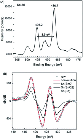 | ||
| Fig. 7 (A) Narrow-scan Sn 3d XPS spectrum and (B) the differentiated AES spectra of the SnO particles synthesized using 30 vol% of OAM. | ||
Shape preservation in SnO2 particles synthesized from SnO particles
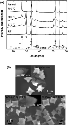
The SnO particles could act as an intermediate for forming SnO2 via annealing in air at 370, 500, and 700 °C for 2 h. The results (Fig. 8) shown correspond to the starfish-like SnO particles obtained using 75 vol% OAM.The conversion of SnO into SnO2 was partial at 370 °C (2 h), became more significant at 500 °C (2 h), and was complete at 700 °C after 2 h (Fig. 8A). At 370 °C, the main phase was still SnO, with some XRD signals (broadened peaks) related to SnO2 (marked with dashed lines) also being observed; these were sharper and better defined in the case of the sample annealed at 500 °C. After annealing at 500 °C, tetragonal SnO2 was obtained as the main phase, while minor peaks were observed at 24.2°, 25.0°, and 35.7° in 2θ; these could be assigned to orthorhombic SnO2. The SnO phase still existed (related peaks were observed at 18.1°, 26.4°, and 50.5° in 2θ) with high contribution after annealing at 370–500 °C as a main phase. After annealing at 700 °C, the XRD patterns showed peaks related primarily to tetragonal SnO2, with minor peaks related to orthorhombic phases also being present.
The oxidation of SnO to SnO2 occurred gradually, as the grain size of SnO became smaller and that of SnO2 became larger with an increase in the annealing temperature; this was determined from the width of the XRD peaks (Fig. 8A). The crystallite sizes of SnO corresponding to the peaks at 29.6° and 33.1° in 2θ were 120 nm for the as-synthesized sample and 30–60 nm for sample annealed at 500 °C. In addition, when the annealing temperature increased from 500 to 700 °C, the crystallite sizes of SnO2 corresponding to the peak at 33.7° in 2θ increased from 15 nm to 30 nm. This did not preclude the possibility that SnO transformed into SnO2 through multiple steps of disproportionation of SnO and other formed intermediate oxides (i.e., 2SnO → Sn3O4 + Sn, Sn3O4 → SnO2 + Sn; other unidentified oxide phases were also observed) and oxidation (Sn + O2 → SnO2), as has been reported for SnO diskettes under similar annealing conditions.13 However, in the present study, the diffraction signals related to the intermediate oxide phases and Sn were not observed in the XRD patterns of the annealed samples at different temperatures (370–700 °C). Based on this result, it was assumed that by simple annealing, the one step disproportionation of SnO (2SnO → SnO2 + Sn) then the oxidation of metallic Sn occurred.
The overall morphology and the multiple-thin-layered structure of the resulting SnO2 particles were identical to those of the as-synthesized SnO micro particles (Fig. 8B). It is likely that the multiple-thin-layered structure of the particles retarded mechanical expansion during the transformation of SnO into SnO2 via annealing at high temperature. This probably helped keeping the particle shape. Lack of the benefit from the thin-layered structure, in general, similar results (crystal structure and morphology) were still achieved for the particles synthesized using 9 vol% OAM under same annealing conditions (Fig. S8A–C†). A few SnO2 particles shaped like assemblies of a number of smaller cubes and square sheets were also observed. These were probably formed by thermal expansion-related cracking and the SnO-to-SnO2 phase-transition-induced strain (Fig. S8D and E†). Furthermore, the optical absorption properties of the as-synthesized and annealed samples (Fig. S9†) were in good agreement with the transformation from SnO, which has an energy gap (Eg) of 2.3 eV, to SnO2 (Eg = 3.5 eV) upon annealing. Thus, the fact that the SnO2 particles exhibited the same morphology as the SnO particles suggested that SnO can be used as a template to produce SnO2 particles with tunable morphology.
Conclusions
In this study, we demonstrated a straightforward approach for synthesizing well-defined single-crystal SnO particles shaped as cubes, assemblies of squares, and starfish-like sheets using tin(II) acetylacetonate as the precursor in a mixture of oleylamine and octadecene. The growth of the SnO particles of different shapes was driven by the differences in the growth rates along the (100), (110), and (001) planes, owing to the interactions with the stabilizing agent, OAM. Finally, it was also proved that the size of SnO particles could be varied easily for a similar shape and the synthesized SnO particles of various shapes could be used as intermediate materials for the synthesis of similar-shaped SnO2 particles.Acknowledgements
This work is partially supported from KAKENHI (A) (24241041 to TY) from JSPS, Japan and Research Grant from Hokkaido University. MTN acknowledge the financial support from F3 program of Hokkaido University. CT thanks the financial support from CEED, Hokkaido University for his stay in Sapporo. A part of this work was also supported by the Advanced Characterization Nanotechnology Platform of the laboratory of Nano–Micro Material Analysis and the XPS laboratry of Hokkaido University as a program of the microstructural characterization platform of Nanotechnology Platform of the Ministry of Education, Culture, Sports, Science and Technology (MEXT), Japan. We acknowledge Ryo Oota, Takashi Tanioka and Dr Yongming Wang for the technical support in TEM observation, Takashi Endo for the technical support in FIB operation, and Keita Suzuki for the technical assistance in AES measurements (Hokkaido University).Notes and references
- D. Aurbach, A. Nimberger, B. Markovsky, E. Levi, E. Sominski and A. Gedanken, Chem. Mater., 2002, 14, 4155 CrossRef CAS.
- K. Sakauchi, Y. Oaki, H. Uchiyama, E. Hosono, H. Zhou and H. Imai, Small, 2010, 6, 776 CrossRef PubMed.
- N. Nitta and G. Yushin, Part. Part. Syst. Charact., 2014, 31, 317 CrossRef CAS.
- L. Y. Liang, Z. M. Liu, H. T. Cao and X. Q. Pan, ACS Appl. Mater. Interfaces, 2010, 2, 1060 CAS.
- A. C. Sharitha, K. S. Sasanka, M. Majeesh, K. Hasna, P. Subha, L. S. Vikas and M. K. Jayaraj, J. Electron Devices, 2014, 19, 1642 Search PubMed.
- S. Kobayashi, T. Kawasuji and N. A. Mori, Chem. Lett., 1994, 23, 217 CrossRef.
- F. R. Abreu, M. B. Alves, C. C. S. Macêdo, L. F. Zara and P. A. Z. Suarez, J. Mol. Catal. A: Chem., 2005, 227, 263 CrossRef CAS.
- J. S. Chen and X. W. Lou, Small, 2013, 9, 1877 CrossRef CAS PubMed.
- H. Wang and A. L. Rogach, Chem. Mater., 2014, 26, 123 CrossRef CAS.
- J. S. Chen and X. W. Lou, J. Am. Chem. Soc., 2008, 130, 12527 CrossRef PubMed.
- T. T. Emons, J. Li and L. F. Nazar, J. Am. Chem. Soc., 2002, 124, 8516 CrossRef CAS PubMed.
- M. Batzill and U. Diebold, Prog. Surf. Sci., 2005, 79, 47 CrossRef CAS.
- Z. R. Dai, Z. W. Pan and Z. L. Wang, J. Am. Chem. Soc., 2002, 124, 8673 CrossRef CAS PubMed.
- Y. Q. Guo, R. Q. Tan, X. Li, J. H. Zhao, Z. L. Luo, C. Gao and W. J. Song, CrystEngComm, 2011, 13, 5677 RSC.
- C. Burda, X. Chen, R. Narayanan and M. A. El-Sayed, Chem. Rev., 2005, 105, 1025 CrossRef CAS PubMed.
- A. Gurlo, Small, 2010, 6, 2077 CrossRef CAS PubMed.
- G. Sun, F. Qi, Y. Li, N. Wu, J. Cao, S. Zhang, X. Wang, G. Yi, H. Bala and Z. Zhang, Mater. Lett., 2014, 118, 69 CrossRef CAS.
- K.-C. Kim, D.-H. Lee and S. Maeng, Mater. Lett., 2012, 86, 119 CrossRef CAS.
- J. Calderer, P. Moninàs, J. Sueiras, E. Llobet, X. Vilanova, X. Correig, F. Masana and A. Rodríguez, Microelectron. Reliab., 2000, 40, 807 CrossRef.
- G. Sun, N. Wu, Y. Li, J. Cao, F. Qi, H. Bala and Z. Zhang, Mater. Lett., 2013, 98, 234 CrossRef CAS.
- M. Z. Iqbal, F. Wang, R. Ud-din, Q. Javed, M. Y. Rafique, Y. Li and P. Li, Mater. Lett., 2012, 68, 409 CrossRef CAS.
- M. Z. Iqbal, F. Wang, T. Feng, H. Zhao, M. Y. Rafique, R. Din, M. H. Farooq, Q. Javed and D. F. Khan, Mater. Res. Bull., 2012, 47, 3902 CrossRef CAS.
- G. Saito, S. Hosokai, M. Tsubota and T. Akiyama, Cryst. Growth Des., 2012, 12, 2455 CAS.
- X. Xu, M. Ge, K. Ståhl and J. Z. Jiang, Chem. Phys. Lett., 2009, 482, 287 CrossRef CAS.
- C. T. Cherian, M. V. Reddy, S. C. Haur and B. V. R. Chowdari, RSC Adv., 2013, 3, 3118 RSC.
- M. Z. Iqbal, F. Wang, Q. Javed, M. Y. Rafique, H. Qiu and G. Nabi, Mater. Lett., 2012, 75, 236 CrossRef CAS.
- J. Ning, Q. Dai, T. Jiang, K. Men, D. Liu, N. Xiao, D. Li, B. Liu, B. Zou, G. Zou and W. W. Yu, Langmuir, 2009, 25, 1818 CrossRef CAS PubMed.
- J. V. Hoene, R. G. Charles and W. M. Hickam, J. Phys. Chem., 1958, 62, 1098 CrossRef.
- N. Pinna, G. Garnweitner, M. Antonietti and M. Niederberger, J. Am. Chem. Soc., 2005, 127, 5608 CrossRef CAS PubMed.
- S. Sun, H. Zeng, D. B. Robinson, S. Raoux, P. M. Rice, S. X. Wang and G. Li, J. Am. Chem. Soc., 2004, 126, 273 CrossRef CAS PubMed.
- W. S. Seo, H. H. Jo, K. Lee, B. Kim, S. J. Oh and J. T. Park, Angew. Chem., 2004, 116, 1135 CrossRef.
- J. Park, E. Kang, S. U. Son, H. M. Park, M. K. Lee, J. Kim, K. W. Kim, H.-J. Noh, J.-H. Park, C. J. Bae, J.-G. Park and T. Hyeon, Adv. Mater., 2005, 17, 429 CrossRef CAS.
- Y. Li, M. Afzaal and P. O'Brien, J. Mater. Chem., 2006, 16, 2175 RSC.
- A. Famengo, S. Anantharaman, G. Ischia, V. Causin, M. M. Natile, C. Maccato, E. Tondello, H. Bertagnolli and S. Gross, Eur. J. Inorg. Chem., 2009, 5017 CrossRef CAS.
- K. M. Nam, J. H. Shim, D.-W. Han, H. S. Kwon, Y.-M. Kang, Y. Li, H. Song, W. S. Seo and J. T. Park, Chem. Mater., 2010, 22, 4446 CrossRef CAS.
- S. Mourdikoudis and L. M. Liz-Marzán, Chem. Mater., 2013, 25, 1465 CrossRef CAS.
- J. Li, H. Li, Z. Wang, L. Chen and X. Huang, J. Power Sources, 2002, 107, 1 CrossRef CAS.
- N. Shukla, C. Liu, M. Jones and D. Weller, J. Magn. Magn. Mater., 2003, 266, 178 CrossRef CAS.
- S. Wang, S. Xie, H. Li, S. Yan, K. Fan and M. Qiao, Chem. Commun., 2005, 507 RSC.
- Y. Duan, Phys. Rev. B: Condens. Matter Mater. Phys., 2008, 77, 045332 CrossRef.
- V. Gorshkov, A. Zavalov and V. Privman, Langmuir, 2009, 25, 7940 CrossRef CAS PubMed.
- M. Niederberger and H. Cölfen, Phys. Chem. Chem. Phys., 2006, 8, 3271 RSC.
- L. Zhou and P. O'Brien, Small, 2008, 4, 1566 CrossRef CAS PubMed.
- R.-Q. Song and H. Cölfen, Adv. Mater., 2010, 22, 1301 CrossRef CAS PubMed.
Footnotes |
| † Electronic supplementary information (ESI) available: SEM, TEM images of powder synthesized using only OD; over-view SEM images of SnO particles synthesized using 1–100 vol%OAM; SEM image of particles synthesized using 9 vol% OAM with various input Sn(acac)2 amount; SEM and cross sectional TEM images of SnO particle synthesized using 9 vol% OAM in the typical synthesis; XRD patterns of particles obtained at various reaction times; FT-IR spectra of purified SnO particles and pure OAM and interpretation; Crystallite size and strain of SnO particles estimated from XRD peak broadening; AES depth profile of SnO particles synthesized using 30 vol% OAM; XRD patterns and SEM images of as-synthesized and annealed particles synthesized using 9 vol% OAM. See DOI: 10.1039/c5ra25676c |
| ‡ Present address: International School of Engineering, Chulalongkorn University, 254 Phyathai Road, Patumwan, Bangkok 10330, Thailand. |
| This journal is © The Royal Society of Chemistry 2016 |

