DOI:
10.1039/C5RA25358F
(Paper)
RSC Adv., 2016,
6, 18198-18203
Photocatalytic H2 generation on macro-mesoporous oxide-supported Pt nanoparticles†
Received
29th November 2015
, Accepted 29th January 2016
First published on 1st February 2016
Abstract
A series of photocatalysts were prepared with crystalline macro-mesoporous oxides and Pt nanoparticles (Pt–TiO2, Pt–Ta2O5, Pt–Nb2O5, Pt–ZrO2, and Pt–Al2O3). Transmission electron microscopy, X-ray diffraction, and N2 adsorption–desorption isotherms reveal that the oxides have prominent macro- and mesoporosity in the crystalline walls. The high surface area and crystalline walls of the oxides play significant roles in photocatalytic H2 production. Pt–TiO2 catalysts show enhanced photocatalytic water splitting efficiency for H2 generation (solar energy conversion efficiency of 1.06%) under a 150 W and 1.5 AM solar simulator. Pt–Ta2O5 and Pt–Nb2O5 also generate noticeable photocatalytic activities of 0.21% and 0.16%, respectively. The enhanced photocatalytic activity is attributed to correct band alignment of the porous oxides with absorption in the UV-visible range, and ordered macro- and mesoporosity of the crystalline oxides for efficient charge transfer.
1 Introduction
Photocatalytic water splitting for the generation of H2 fuel under solar light illumination has been studied as a clean and renewable energy technology that overcomes the limitations of fossil fuels.1–7 This thermodynamically uphill, two-electron reaction requires 237 kJ mol−1 to split a water molecule into H2 and O2.8 Despite the revolutionary Fujishima–Honda effect discovered in 1972, photocatalytic/photo-electrochemical H2 production is still challenging to achieve.9 Construction of a stable and practical solar power system with economic viability is highly demanding. Several factors have been proven to affect the solar-to-H2 energy conversion efficiencies, including morphology, surface area, crystallinity, and band structure of the catalyst and charge transfer at oxide–metal interfaces.10,11 Transition metal oxides with ordered pore structures have numerous catalytic applications.12–15 In heterogeneous catalysis, it is known that the interaction between metal nanoparticles and oxide supports plays a crucial role in determining the catalytic activity.16,17 Especially, mesoporous metal oxides with a crystalline wall possess not only high thermal and mechanical stability, but also specific electronic orbitals and lattice defects that influence catalytic performance and photocatalytic efficiencies.18,19 Many different kinds of mesoporous oxides have been prepared using a soft template, such as block copolymers that have both hydrophilic and hydrophobic groups.20,21 As an alternative route, the nanocasting method is employed, in which a hard template e.g. a polymer bead or silica sphere is used as a sacrificial template.22 However there are some limitations to directly comparing the catalytic effect of different mesoporous oxides because each oxide has a different pore size, channel structure, and surface area. Furthermore, some mesoporous oxides do not have large enough pore sizes and volumes to load metal nanoparticles and create supported catalysts. Recently, mesoporous oxides with macropores were prepared using dual templates. Dacquin et al. reported highly ordered macro-mesoporous aluminas with bimodal pore structures.23 In their report, Pluronic P123 triblock copolymer was used as the structuring agent to form the mesopores, while monodispersed polystyrene beads created macropores in the crystalline walls of the mesostructures.
In this study, we prepared macro-mesoporous oxides that have crystalline and well-defined macro- and meso-frameworks. Using P123 as the soft template and polystyrene beads with an average diameter of 500 nm as the hard template, we generated crystalline macro-mesoporous oxides of TiO2, Ta2O5, Nb2O5, ZrO2, and Al2O3 that contain 300 nm macropores in mesoporous frameworks. By supporting colloidal Pt nanoparticles in the oxides, we prepared supported photocatalysts i.e. Pt–TiO2, Pt–Ta2O5, Pt–Nb2O5, Pt–ZrO2, and Pt–Al2O3. With a set of oxide-supported Pt-nanoparticle photocatalysts, photocatalytic water splitting experiments were conducted for the generation of H2. We observed enhanced photocatalytic activity following the introduction of Pt and macro-mesoporous structures with crystalline walls. Following which, we investigated the correlation between the type of macro-mesoporous oxide and the photocatalytic water splitting efficiency.
2 Experimental
2.1 Synthesis of macro-mesoporous oxide
Macro-mesoporous oxides were prepared using the dual templating method, in which Pluronic P123 surfactant and polystyrene beads were used as soft and hard templates, respectively. Potassium persulfate (0.03 g dissolved in water) was added as an initiator for the polymerization. The polystyrene beads were synthesized through emulsifier-free emulsion polymerization.24 Briefly, 14 g styrene monomer and 0.7 g divinyl benzene as a cross linker were washed 4 times with a 0.1 M NaOH solution to remove inhibitors, and then washed with DI water 4 times. The solution was mixed with 140 mL DI water at 70 °C and purged by flowing Ar for 1 h. For initiation, 0.03 g potassium persulfate dissolved in 2 mL water was added to the solution. Upon addition of the initiator, polymerization took place; the reaction was then maintained at 70 °C for 12 h. White solids containing the polystyrene beads were obtained by centrifugation after washing with methanol and water. To synthesize the meso-macroporous oxides, metal chloride or alkoxide precursors were dissolved in an acidic solution in the presence of P123 and mixed thoroughly under vigorous stirring for the sol–gel reaction. The polystyrene beads were added to the precursor solution before the evaporation-induced self-assembly step. For the macro-mesoporous alumina, 4.0 g P123 ((EO)20(PO)70(EO)20 triblock copolymer (EO = ethylene oxide, PO = propylene oxide, Mw = ∼5800)) was dissolved in 40 mL ethanol for 4 h. For the precursor solution, 8.16 g aluminum isopropoxide was dissolved in 20 mL ethanol and 6.4 mL 68–70 wt% nitric acid, and then this precursor solution was added drop wise into the P123 solution. For the macro-mesoporous Nb2O5 and Ta2O5, 30 mmol niobium chloride or tantalum chloride, respectively, was dissolved in 30 mL ethanol with 3 g P123. For the macro-mesoporous TiO2 and ZrO2, 20 mmol titanium isopropoxide or zirconium isopropoxide, respectively, in 70 wt% 1-propanol was added to a P123 solution that also contained ethanol and HCl. Each precursor solution mixed with P123 was stirred for 5 h; 4 g dried polystyrene beads (powder) was then added to the solution. The mixture solution was placed on a hot plate at 60 °C for 48 h for solvent evaporation. The collected solid was calcined in a muffle furnace at 700 °C for 6 h (for Al2O3, 900 °C for 10 h) in air. Through calcination, we obtained crystalline macro-mesoporous Al2O3, TiO2, Nb2O5, Ta2O5, and ZrO2 with an average pore size of 300 nm.
2.2 Deposition of Pt on macro-mesoporous oxide
To synthesize the 2.7 nm Pt nanoparticles, we mixed H2PtCl6·xH2O, and Pt(acac)2 as the precursor; poly(vinylpyrrolidone) and the precursor were then added to ethylene glycol in a 50 mL three-necked flask. The mixture was then heated to 200 °C and maintained at this temperature for 10 min under Ar gas. The solution was precipitated with excess acetone and re-dispersed in ethanol.25 To prepare the oxide-supported Pt-nanoparticle photocatalysts, the desired amount of macro-mesoporous oxide was added to poly(vinylpyrrolidone) (PVP)-capped Pt nanoparticles dispersed in ethanol26 and sonicated for 2 h. The catalysts were collected by centrifugation and dried. To remove the organic capping molecules, the catalysts were calcined at 360 °C for 6 h in air.
2.3 Characterization of photocatalysts
High-resolution transmission electron microscopy (HR-TEM) images of the Pt nanocatalyst were obtained using a JEOL JEM-ARM200F (Cs-corrected scanning transmission electron microscope). The morphology was characterized using scanning electron microscopy (SEM, Magellan 400). The oxidation states of the catalysts were investigated using XPS. The XPS spectra were taken using a Thermo VG Scientific Sigma Probe system equipped with an Al-Kα X-ray source (1486.3 eV) with an energy resolution of 0.47 eV FWHM under ultra-high vacuum at 10−10 Torr. The amount of Pt nanoparticles loaded on the oxide powder was measured by inductively coupled plasma atomic emission spectroscopy (ICP-AES). XRD patterns were measured on a Bruker D8 GADDS diffractometer using Co Kα radiation (1.79 Å). Nitrogen physisorption data was obtained on a Micromeritics ASAP 2020.
2.4 Photocatalytic hydrogen evolution measurement
The photocatalytic H2 production reactions were performed in a Pyrex top, irradiation-type vessel connected to a closed gas circulation system at room temperature. A 0.1 g sample was dispersed in 100 mL of an aqueous solution i.e. 10 mL methanol (10 vol%) and 90 mL ultrapure water. The reactant solution was evacuated several times to ensure complete air removal, followed by the introduction of back-filled argon (ca. 5 kPa) into the system. The reaction was initiated by irradiation with a 150 W solar simulator (1.5 AM, 1 sun). The reaction was carried out at a power of 50 mW cm−2 with an irradiation area of 19.6 cm2. The evolved gases were analyzed by online gas chromatography (DS Science with a TCD detector and MS-5A column, and argon carrier gas). The photocatalytic H2 evolution activity was estimated from the initial gas evolution rate.
3 Results and discussion
3.1 Characterization of oxide-supported Pt-nanoparticle photocatalysts
Macro-mesoporous oxides are prepared using the dual templating method in which Pluronic P123 surfactant and polystyrene beads are used as soft and hard templates, respectively. When metal chloride or alkoxide precursors are cured by the sol–gel reaction in the presence tri-block copolymer P123 and polystyrene beads, porous oxides having both meso- and macropores are obtained after calcination. At high temperatures i.e. above 700 °C, the inorganic frameworks are crystallized and the organic polymers are burned out, generating dual-pore structures (Fig. 1a). When PVP-capped Pt nanoparticles with an average diameter of 2.7 nm are deposited into the pores of the oxides, oxide-supported Pt-nanoparticle photocatalysts are produced with high loading (ca. 1 wt% Pt in the catalyst).
 |
| | Fig. 1 (a) Illustration of the preparation of macro-mesoporous oxides using P123 and polystyrene beads and the corresponding oxide-supported Pt nanoparticle catalysts. (b–e) Representative TEM images of (b and c) Pt–Nb2O5 and (d and e) Pt–Ta2O5 catalysts showing the macro-mesoporous dual structures. | |
Fig. 1a illustrates the detailed synthesis procedure for the preparation of the macro-mesoporous oxides and their supported Pt nanoparticle catalysts. Representative transmission electron microscopy (TEM) images in Fig. 1b and d reveal that the as-prepared Nb2O5 and Ta2O5 have distinct macropores with an average diameter of 300 nm traced by the removal of the polystyrene beads at high temperature. In addition, the macroporosity of the oxide-supported Pt-nanoparticle photocatalysts is observed using FE-SEM (Fig. S1 in ESI†). The FE-SEM images in Fig. S1(a) and (b)† show an ordered macroporous structure and well-interconnected macropores. It is clear that the Pt nanoparticles are evenly incorporated in the macropores without agglomeration, as shown in Fig. S1(c) and (d).† The TEM images shown in Fig. 1c and e of Pt–Nb2O5 and Pt–Ta2O5, respectively, contain mesoporosity that can shorten the diffusion length to a few nanometers, thus facilitating charge transfer. From these morphological studies, we can confirm that the oxide-supported Pt nanocatalysts have dual-pore structural morphologies consisting of macro- and mesoporosity and that the Pt nanoparticles are incorporated into the inner pores. The presence of ordered macroporosity as well as mesoporosity could synergistically boost light harvesting and charge transfer.27 The mesoporous nature of the oxide photocatalysts is confirmed from N2 sorption studies (Fig. 2). In the adsorption–desorption isotherms in Fig. 2a, each oxide i.e. TiO2, Nb2O5, ZrO2, and Al2O3—excluding Ta2O5—display a typical type-IV hysteresis loop, which is a characteristic of mesoporous materials with uniform pore structure. The pore size distributions calculated from the nitrogen sorption isotherm are shown in the Fig. 2b. The mesopores created by P123 ranged in size from 2.8 to 11.8 nm, which are all in the mesoporous range. The physicochemical characterization data i.e. surface area, pore size, and pore volume are summarized in Table 1. The porosity of the oxide-supported Pt-nanoparticle photocatalysts can be retained at temperatures as high as 700 °C, indicating high thermal stability. Ta2O5, Nb2O5, and Al2O3 show higher surface areas of 96.7, 102.9, and 123.6 m2 g−1, respectively, whereas TiO2 and ZrO2 show much lower surface areas. Through TEM images (Fig. S2†), we confirmed that the low surface area in the case of Pt–TiO2 is associated with mesopores created by agglomerated TiO2 nanoparticles. The characteristic features of the crystalline walls can be identified from X-ray diffraction (XRD) studies (Fig. 3). Anatase TiO2 with dominant (101) peaks, orthorhombic L- or β-Ta2O5, pseudo-hexagonal Nb2O5, tetragonal ZrO2, and gamma-phase Al2O3 are identified by the Joint Committee on Powder Diffraction Standards i.e. JCPDS. Well-defined peaks corresponding to the crystal structure of each oxide are clearly evident. Small-angle X-ray diffraction (XRD) patterns of the calcined Pt-oxide photocatalysts (Pt–TiO2, Pt–Ta2O5, Pt–Nb2O5) are shown in Fig. S3b in ESI.† Strong peaks in the region of 2θ = 0.44–0.632° correspond to mesostructures, which imply that the photocatalysts keep their porous structure after calcination at high temperature. Mesoporosity with crystalline walls results in faster diffusion and more efficient transfer of charge carriers from the bulk to the surface by suppressing the recombination of holes and electrons.19 To access the optical response of the oxide-supported Pt nanoparticle catalysts, we studied the UV-Vis absorbance spectra (Fig. 4). The UV-Vis absorbance spectra showed Pt–TiO2 absorbed in the visible light (>400 nm) region while Pt–Nb2O5 and Pt–Ta2O5 only absorbed light in the UV range. The onset of absorbance for Pt–Al2O3 and Pt–ZrO2 started near the IR region; alumina and zirconia are generally considered to be insulators because of direct wide band gaps. The band gap energy of macro-mesoporous oxides obtained from the UV-Vis absorbance is similar to their theoretical band gap values. To confirm the efficiency of charge carrier transfer by Pt doping, photoluminescence (PL) measurements were carried out. PL spectra of Pt–TiO2, Pt–Ta2O5, and Pt–Nb2O5 exhibit quenching, in comparison with the oxide support without Pt nanoparticles (Fig. S4 in ESI†). However, Pt–Al2O3 and Pt–ZrO2 did not show any quenching behaviour even after Pt nanoparticles were introduced to the oxide support. In particular, the PL intensity of Pt–TiO2 shows the most significantly diminished PL intensity, compared with the bare oxide; a lower PL intensity indicates a reduced charge recombination process. Thus, photoinduced electrons from the TiO2 can be injected into the Pt nanoparticles by formation of a Schottky barrier at the Pt and TiO2 interface that demonstrates efficient charge transfer. In addition, we carried out X-ray photoelectron spectroscopy to study the influence of the oxidation state of Pt on photocatalytic activity. Fig. S5 in ESI† shows the XPS peaks of Pt in the oxide-supported Pt-nanoparticle photocatalysts; in all of the photocatalysts, Pt is mainly present in its metallic state. The presence of a high percentage of metallic Pt nanoparticles acts as a co-catalyst for efficient charge transfer.
 |
| | Fig. 2 (a) Nitrogen adsorption–desorption isotherms and (b) pore size distribution curves deduced from the adsorption branches of TiO2, Ta2O5, Nb2O5, ZrO2, and Al2O3. | |
Table 1 Physico-chemical characterization data of BET surface area, pore size, pore volume, theoretical band gaps, and solar energy conversion efficiency of the oxide-supported Pt nanoparticle catalysts
| Photocatalyst |
SBET (m2 g−1) |
Vporea (cc g−1) |
Dporeb (nm) |
Ptc (wt%) |
Conv.d (%) |
| Pore volume. Pore size. Pt loading/ICP. Solar energy conversion efficiency. |
| Pt–TiO2 |
12.9 |
0.045 |
11.8 |
1.20 |
1.06 |
| Pt–Ta2O5 |
96.7 |
0.068 |
2.8 |
1.11 |
0.21 |
| Pt–Nb2O5 |
102.9 |
0.098 |
3.8 |
1.04 |
0.17 |
| Pt–ZrO2 |
19.2 |
0.047 |
9.7 |
1.16 |
— |
| Pt–Al2O3 |
123.3 |
0.206 |
6.6 |
1.09 |
— |
 |
| | Fig. 3 X-ray diffraction (XRD) patterns of TiO2, Ta2O5, Nb2O5, ZrO2, and Al2O3. | |
 |
| | Fig. 4 UV-Vis absorbance of the oxide-supported Pt nanoparticle catalysts i.e. Pt–TiO2, Pt–Ta2O5, Pt–Nb2O5, Pt–ZrO2, and Pt–Al2O3. | |
3.2 Photocatalytic water splitting for H2 generation
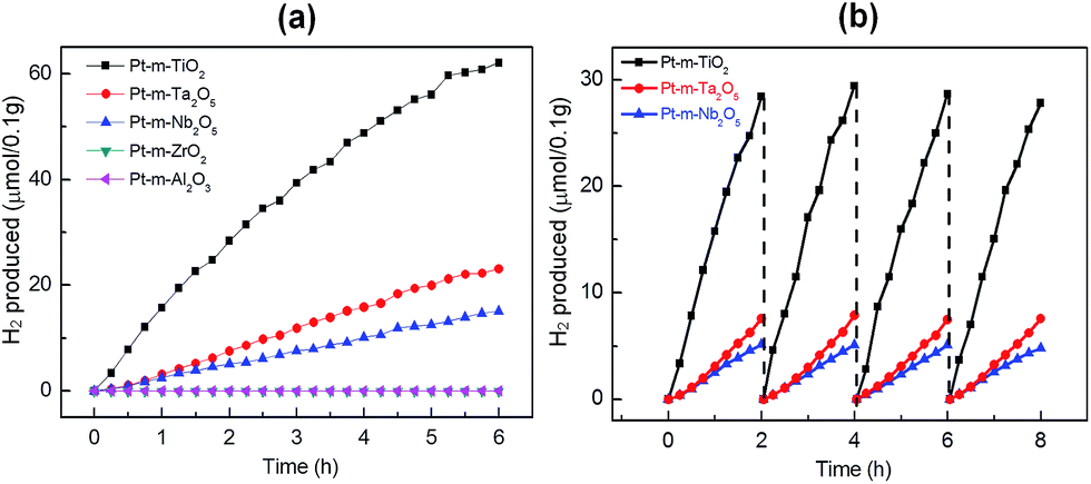
Ordered macro-mesoporous oxides have been employed for higher photocatalytic activity in the past few decades because of better mass and radiation transport through the ordered porous network.28,29 Recently, Naik et al. reported hierarchical porous N-doped TiO2 photocatalysts for enhanced photogeneration of H2 in solar light.5 To investigate the effect of macro-mesoporous oxides, photocatalytic H2 production under simulated solar light was carried out using 10 volume% methanol solutions as sacrificial agents over the oxide-supported Pt-nanoparticle photocatalysts. We did not observe any H2 production in the absence of either light or catalyst. Among the oxide-supported Pt-nanoparticle photocatalysts, Pt–TiO2 showed the highest photocatalytic H2 generation activity (157.5 μmol g−1 h−1), as shown in Fig. 5a. Pt–Ta2O5 (31.3 μmol g−1 h−1) and Pt–Nb2O5 (24.9 μmol g−1 h−1) also exhibited a considerable amount of photocatalytic H2 generation. However, Pt–Al2O3 and Pt–ZrO2 catalysts did not evolve any photocatalytic H2 because they can only be excited under UV-light irradiation due to their large bandgaps. The measured solar energy conversion efficiencies are 1.06% for Pt–TiO2, 0.21% for Pt–Ta2O5, and 0.17% for Pt–Nb2O5 (Table 1). Fig. 5b shows the time-dependent study of H2 evolution for Pt–TiO2 i.e. the best-performing catalyst; the catalyst evolved 28.4 μmol of H2 in the initial two hours of photocatalytic reaction. After two hours of reaction, the reactor was evacuated, backfilled with Ar, and then the photocatalytic experiment was repeated. The activity was found to be almost the same in four successive runs, without any decrease after 8 h. Additionally, the Pt–Ta2O5 and Pt–Nb2O5 catalysts revealed no decrease in activity even after the 4th cycle i.e. after 8 h. This demonstrates the photo-stability of these catalysts and that they can be used for a long time. Photocatalytic water-splitting results for the Pt–TiO2 photocatalyst i.e. that has the highest solar energy conversion efficiency of 1.06% are compared with those in the recent report by Zhang et al. where hierarchical ordered macro-mesoporous anatase calcined at 400 °C exhibited 0.23% quantum efficiency.30 Previously, our ordered hierarchical porous N-doped TiO2 photocatalyst with Pt nanoparticles had a quantum efficiency of 1.38%. For comparison, the N-doped Pt–TiO2 photocatalyst with macroporosity exhibits lower efficiency (0.58%), indicating that the macro-mesoporous structure has an advantage in improving photocatalysis activity for H2 evolution.15 The exceptionally high photocatalytic water splitting activity of Pt–TiO2 could also be attributed to the red shift of the absorption and the presence of the macro-mesoporous structure with crystalline walls. Obviously, the UV-Vis diffuse absorption spectra of Pt–TiO2 displayed a significant shift in absorption to the visible light region. Moreover, the suitable band position and band gap of TiO2 is valuable to initiate hydrogen production. In photocatalytic water splitting for the production of H2, the position of the conduction band should be above the hydrogen reduction potential and the valence band should be below the oxygen oxidation potential; all three photoactive oxides fulfil these requirements (Fig. 6a). As the solar simulator intensity is much higher in the visible range, the Pt–TiO2 catalyst therefore shows much higher activity than Pt–Ta2O5 and Pt–Nb2O5. Fig. 6b illustrates the mechanism for photocatalytic H2 generation by light absorption and charge transfer in the macro-mesoporous oxide-supported Pt-nanoparticle photocatalysts. The presence of ordered meso- and macro-porosities with a higher effective surface area facilitates more active sites for the reaction, resulting in higher activity. Apart from surface area, the crystalline walls of the porous oxides play a significant role in the high photocatalytic activity. The crystallized anatase phase facilitated rapid transfer of photoelectrons from the bulk to the surface, which could effectively inhibit recombination of the photo-generated electrons and holes to improve the photocatalytic activity. The higher photocatalytic activity may also be attributed to a combination of the following synergetic effects: the dual pore structure of the catalyst with crystalline domains plays the most important role for the photocatalytic process. Ordered macroporosity serves as the light harvesting medium and provides multiple reflections3 owing to its capacity for easy transport of the reactant mass and radiation. The presence of mesoporosity helps to shorten the diffusion length of charge carriers from the bulk to the surface for efficient charge transfer.31 Apart from charge separation, the mesoporosity introduces a higher surface area and hence more active sites for photocatalysis. The deposited Pt nanoparticles create a Schottky barrier with porous semiconductor oxides acting as co-catalysts and promoting charge transfer.32–35 It is believed that the red shift in the longer wavelength range is related to the presence of new electronic states produced by the deposition of Pt nanoparticles.35 The synergistic effects of visible light absorption, fast diffusion of charge carriers, and effective transfer are vital parameters for enhancing visible-light photocatalytic activity.
 |
| | Fig. 5 (a) Photocatalytic H2 generation by Pt-macro-mesoporous oxides. (b) Time-dependent study of photocatalytic H2 generation by Pt-mesoporous TiO2, Pt-mesoporous Ta2O5 and Pt-mesoporous Nb2O5. | |
 |
| | Fig. 6 (a) Band structures of oxide photocatalysts relative to redox potential. (b) Mechanism for photocatalytic H2 generation by light absorption and charge transfer through Pt–TiO2 photocatalysts. | |
4 Conclusions
In conclusion, we investigated the role of ordered macro-mesoporous oxides with crystalline walls for photocatalytic water splitting to generate H2. Among the oxide-supported Pt-nanoparticle photocatalysts, Pt–TiO2 exhibits 1.06% solar energy conversion efficiency, followed by Pt–Ta2O5 (0.21%) and Pt–Nb2O5 (0.16%), while there is no generation of H2 on Pt–Al2O3 and Pt–ZrO2. The high photocatalytic activity of the Pt–TiO2 photocatalyst is attributed to proper position of the band structure. Ordered macro-mesoporosity of the oxide is responsible for enhanced mass and electromagnetic radiation transport, and multiple internal reflections boosting light harvest. The crystalline walls of the porous oxides facilitate charge separation with faster diffusion in the crystalline channel. The presence of Pt at the surface results in the formation of a Schottky barrier at the metal–oxide interface, which facilitates interfacial electron transfer and subsequently encourages charge carrier separation. As a result, charge carrier transfer is remarkably improved, which in turn results in enhanced photocatalytic H2 generation.
Acknowledgements
The work was supported by IBS-R004-G4 and partly by the 2015 Research Fund (1.150109.01) of UNIST.
Notes and references
- A. J. Bard and M. A. Fox, Acc. Chem. Res., 1995, 28, 141–145 CrossRef CAS.
- K. Maeda, K. Teramura, D. L. Lu, T. Takata, N. Saito, Y. Inoue and K. Domen, Nature, 2006, 440, 295 CrossRef CAS PubMed.
- M. G. Walter, E. L. Warren, J. R. McKone, S. W. Boettcher, Q. X. Mi, E. A. Santori and N. S. Lewis, Chem. Rev., 2010, 110, 6446–6473 CrossRef CAS PubMed.
- Z. G. Zou, J. H. Ye, K. Sayama and H. Arakawa, Nature, 2001, 414, 625–627 CrossRef CAS PubMed.
- B. Naik, S. M. Kim, C. H. Jung, S. Y. Moon, S. H. Kim and J. Y. Park, Adv. Mater. Interfaces, 2014, 1, 1300018 Search PubMed.
- N. Zhang, S. Q. Liu and Y. J. Xu, Nanoscale, 2012, 4, 2227–2238 RSC.
- N. Zhang, M. Q. Yang, S. Q. Liu, Y. G. Sun and Y. J. Xu, Chem. Rev., 2015, 115, 10307–10377 CrossRef CAS PubMed.
- K. Maeda and K. Domen, J. Phys. Chem. Lett., 2010, 1, 2655–2661 CrossRef CAS.
- A. Fujishima and K. Honda, Nature, 1972, 238, 37 CrossRef CAS PubMed.
- M. A. Fox and M. T. Dulay, Chem. Rev., 1993, 93, 341–357 CrossRef CAS.
- J. Y. Park, S. M. Kim, H. Lee and B. Naik, Catal. Lett., 2014, 144, 1996–2004 CrossRef CAS.
- M. E. Davis, Nature, 2002, 417, 813–821 CrossRef CAS PubMed.
- Y. Ren, Z. Ma and P. G. Bruce, Chem. Soc. Rev., 2012, 41, 4909–4927 RSC.
- A. Taguchi and F. Schuth, Microporous Mesoporous Mater., 2005, 77, 1–45 CrossRef CAS.
- B. Naik, S. Y. Moon, S. H. Kim and J. Y. Park, Appl. Surf. Sci., 2015, 354, 347–352 CrossRef CAS.
- D. Park, S. M. Kim, S. H. Kim, J. Y. Yun and J. Y. Park, Appl. Catal., A, 2014, 480, 25–33 CrossRef CAS.
- G. A. Somorjai and J. Y. Park, Angew. Chem., Int. Ed., 2008, 47, 9212–9228 CrossRef CAS PubMed.
- C. Jo, Y. Seo, K. Cho, J. Kim, H. S. Shin, M. Lee, J. C. Kim, S. O. Kim, J. Y. Lee, H. Ihee and R. Ryoo, Angew. Chem., Int. Ed., 2014, 53, 5117–5121 CAS.
- J. Lee, M. C. Orilall, S. C. Warren, M. Kamperman, F. J. Disalvo and U. Wiesner, Nat. Mater., 2008, 7, 222–228 CrossRef CAS PubMed.
- G. J. D. A. Soler-Illia, E. L. Crepaldi, D. Grosso and C. Sanchez, Curr. Opin. Colloid Interface Sci., 2003, 8, 109–126 CrossRef CAS.
- D. H. Wang, R. Kou, D. Choi, Z. G. Yang, Z. M. Nie, J. Li, L. V. Saraf, D. H. Hu, J. G. Zhang, G. L. Graff, J. Liu, M. A. Pope and I. A. Aksay, ACS Nano, 2010, 4, 1587–1595 CrossRef CAS PubMed.
- P. D. Yang, T. Deng, D. Y. Zhao, P. Y. Feng, D. Pine, B. F. Chmelka, G. M. Whitesides and G. D. Stucky, Science, 1998, 282, 2244–2246 CrossRef CAS PubMed.
- J. P. Dacquin, J. Dhainaut, D. Duprez, S. Royer, A. F. Lee and K. Wilson, J. Am. Chem. Soc., 2009, 131, 12896 CrossRef CAS PubMed.
- M. Park, K. Gandhi, L. Sun, R. Salovey and J. J. Aklonis, Polym. Eng. Sci., 1990, 30, 1158–1164 CAS.
- T. Teranishi, M. Hosoe, T. Tanaka and M. Miyake, J. Phys. Chem. B, 1999, 103, 3818–3827 CrossRef CAS.
- K. An, S. Alayoglu, N. Musselwhite, K. Na and G. A. Somorjai, J. Am. Chem. Soc., 2014, 136, 6830–6833 CrossRef CAS PubMed.
- C. M. A. Parlett, K. Wilson and A. F. Lee, Chem. Soc. Rev., 2013, 42, 3876–3893 RSC.
- T. Brezesinski, J. Wang, S. H. Tolbert and B. Dunn, Nat. Mater., 2010, 9, 146–151 CrossRef CAS PubMed.
- Y. Li, Z. Y. Fu and B. L. Su, Adv. Funct. Mater., 2012, 22, 4634–4667 CrossRef CAS.
- R. Y. Zhang, D. K. Shen, M. Xu, D. Feng, W. Li, G. F. Zheng, R. C. Che, A. A. Elzatahry and D. Y. Zhao, Adv. Energy Mater., 2014, 4, 1301725 Search PubMed.
- K. Sivaranjani and C. S. Gopinath, J. Mater. Chem., 2011, 21, 2639–2647 RSC.
- J. Y. Park, J. R. Renzas, B. B. Hsu and G. A. Somorjai, J. Phys. Chem. C, 2007, 111, 15331–15336 CAS.
- J. Y. Park, L. R. Baker and G. A. Somorjai, Chem. Rev., 2015, 115, 2781–2817 CrossRef CAS PubMed.
- S. M. Kim, S. J. Lee, S. H. Kim, S. Kwon, K. J. Yee, H. Song, G. A. Somorjai and J. Y. Park, Nano Lett., 2013, 13, 1352–1358 CrossRef CAS PubMed.
- B. K. Vijayan, N. M. Dimitrijevic, J. S. Wu and K. A. Gray, J. Phys. Chem. C, 2010, 114, 21262–21269 CAS.
Footnotes |
| † Electronic supplementary information (ESI) available: Experimental data including FE-SEM (Fig. S1), HR-TEM (Fig. S2), small-angle XRD patterns (Fig. S3) and XPS (Fig. S4). Photoluminescence (Fig. S5). See DOI: 10.1039/c5ra25358f |
| ‡ These authors contributed equally to this work. |
|
| This journal is © The Royal Society of Chemistry 2016 |
Click here to see how this site uses Cookies. View our privacy policy here.