Fabricating binary anti-corrosion structures containing superhydrophobic surfaces and sturdy barrier layers for Al alloys

Yinghao Wuab, Wenjie Zhao*a, Wurong Wangb and Wenjie Suia
aKey Laboratory of Marine Materials and Related Technologies, Zhejiang Key Laboratory of Marine Materials and Protective Technologies, Ningbo Institute of Materials Technology and Engineering, Chinese Academy of Sciences, Ningbo 315201, China. E-mail: zhaowj@nimte.ac.cn; Tel: +86-0574-86694901
bSchool of Materials and Engineering, Shanghai University, Shanghai 200000, China

Received 26th November 2015 , Accepted 23rd December 2015

First published on 4th January 2016


Abstract

Aluminum alloys with novel binary anti-corrosion structures on the surface showing superhydrophobic properties were fabricated via chemical etching, anodic oxidation and chemical modification. Surface morphologies and chemical elements of the as-prepared films were investigated by Fourier transform infrared spectrometer, scanning electron microscopy and confocal laser scanning microscope. Surface wettability was investigated by the contact angle meter. Manipulation of surface morphology by anodic oxidation current density and the influence of surface chemical modification on the wettability were investigated. The anti-corrosion properties of the as-prepared films were characterized using an electrochemistry workstation. The results showed that surface water contact angle could reach 156° after chemical modification when the current density of anodic oxidation was 5 A dm−2. The corrosion potential (Ecorr) was positively increased from −1189 mV for bare Al alloys to −304 mV for the samples anodized at 5 A dm−2. The synergetic effect between the protective properties of air trapped in a low adhesion superhydrophobic surface and good barrier properties of the barrier layer of anodic oxidation film was remarkably enhanced the corrosion resistance of aluminum alloys. Influences of the anodic oxidation current density and the self-assembled films on the anti-corrosion performance were discussed in detail.
1. Introduction

Aluminum and aluminum alloys are widely used in the architectural, automotive and ocean environments for both technical and economic considerations,1 which is the largest usage amount of metal materials in industry, second only to steel.2 However, Al alloys are reactive and the demands of corrosion resistance for some applications cannot be met. In order to improve the corrosion resistance properties of Al alloys, the surface modification technology has developed rapidly in recent years, which is related to electrochemistry, chemistry, metallography, and other disciplines.3–8 The surface modification of Al alloys is generally consisted of chemical etching, anodic oxidation, coating, and etc.9–12 It has been reported that the chemical modified samples which present superhydrophobicity can enhance the corrosion resistance of Al alloys.13–15 The resulting superhydrophobic performance is attributed to the combined effects of micro/nano-structure on Al alloys surface and the modification of low surface energy materials.

Chemical etching can enhance the surface roughness values of Al alloys,16,17 thus leads to the enhancement of both the hydrophobic and hydrophilic properties.18,19 Yin et al.20 fabricated a superhydrophobic film on Al alloys by chemical etching and surface modification. The Al alloys were covered by etch pits and rather rougher than untreated surface. The superhydrophobic surface modified by fluorosilane significantly improved the corrosion resistance of Al alloys with a WCA of 161.2°. Xianming Shi et al.15 also revealed that nano-silica particles deposited on acid-etched aluminum substrates present superhydrophobic property, when the surface roughness value of Ra exceeds 450 nm, contact angle was greater than 154°. The electrochemical data suggested that the superhydrophobic surface enhanced the corrosion resistance of Al alloys. Although the micro/nano-binary structure fabricated by chemical etching meet the need of surface superhydrophobicity, the convexities on etched Al alloys can hold a large amount of corrosion medium which will decrease the anti-corrosion of Al alloys.

As a cost-effective and ready-to-implement process, anodic oxidation was applied extensively on Al alloys to improve the corrosion resistance.21–23 Kong et al. found that the anodic oxidation could improve the corrosion resistance of Al alloys. After anodic oxidation, the barrier layer of Al2O3 on Al alloys surface remarkably prevented the corrosive anions from entering the substrate to improve the corrosion resistance.5 However, there are many nanopores on the anodized sample surfaces, of which the chloride ions in liquid can stay in the pores. As time going on, the chloride ions could permeate the barrier film and corrode the aluminum substrate. The superhydrophobic surface can protect the aluminum substrate from corrosion.24–26 Li et al.24 fabricated a superhydrophobic surface by anodic oxidation and self-assembly. The influence of anodic oxidation current density and the self-assembly time were studied. The result of electrochemical measurement indicated that the anti-corrosion performance of Al alloys was greatly improved by the self-assembled superhydrophobic film. It also showed that changing the anodic oxidation condition can manipulate the surface morphology of Al alloys.27–29 Ludmila Boinovich revealed the synergetic effect of superhydrophobic surface and good barrier properties of the oxide sublayer which fabricated by laser treatment could remarkably enhanced the corrosion resistance of aluminum alloys.30

To the best of our knowledge, many studies have been previously carried out about the independent effect of anodic oxide films and surface superhydrophobicity on the anti-corrosion properties. However, utilizing the synergistic effect of anodic oxide films and surface superhydrophobicity (especially the regular binary structure fabricated by anodic oxidation) to prepare the anti-corrosion films, was rarely referred to. In particular, it is necessary to explore the relationship between the anti-corrosion properties and the binary structures on Al alloys surface manipulated by anodic oxidation current density.

Inspired by the above-mentioned influences of surface morphology and chemical modification on corrosion resistance, in this work, Al alloys surfaces were treated by an acid etching, anodic oxidation and chemical modification method. A versatile procedure combining micro/nano-binary structures, anodic oxidation porous films and further modification with low-surface-energy molecules were proposed to fabricate excellent anti-corrosion films on Al alloys substrates. The various anodic current densities were used to manipulate the surfaces morphology of Al alloys. Electrochemical and surface analysis methods were used in this paper to revel the corresponding synergetic corrosion resistance of anodic oxide films with various micro/nano-structure manipulated by anodic oxidation current density and chemical modification.

2. Experimental

2.1. Preparation of self-assembled monolayers (SAMs)

1H,1H,2H,2H-Perfluorooctyltriethoxysilane [CF3(CF2)5(CH2)2Si(OCH2CH3)3, PTES] was obtained from Aladdin and used without further purification. Other chemical compounds used were analytical grade. All the aqueous electrolyte solutions used here were obtained using deionized water.

The experimental material is 2024 Al alloys with the chemical compositions as follows: 4.5%Cu, 1.5%Mg, 0.5%Fe, 0.6%Mn, 0.5%Si, 0.5% others and Al as the remainder. The Al alloys with a size of 25 mm × 25 mm × 5 mm were used as substrate. The substrates were ground by emery paper (no. 400, 800, 1200) gradually, and polished, then ultrasonically cleaned in acetone–ethanol and deionized water for 10 min, respectively. The substrates were chemically etched by hydrochloric acid solution (VHCl[thin space (1/6-em)]:[thin space (1/6-em)]VH2O = 1[thin space (1/6-em)]:[thin space (1/6-em)]2) for 3 min. All the etched samples were ultrasonically cleaned with deionized water to remove any residual dust particles formed in the pores. The anodic oxidation was carried out using constant current operation in 4.5 g L−1 sulfuric acid solution for 30 min, the anodic oxidation current density varied from 2 A dm−2 to 6 A dm−2 (included 2 A dm−2, 3 A dm−2, 4 A dm−2, 5 A dm−2, 6 A dm−2). After ultrasonically cleaned with deionized water the samples were dried by N2. Then the as-prepared samples were immersed in 5 mM PTES solution in a mixture of ethanol and water (the volume ratio of ethanol and water was 1[thin space (1/6-em)]:[thin space (1/6-em)]1) at 60 °C. After 6 h, the obtained specimens were taken out and then dried at 60 °C for 2 h. The fabrication procedure of forming the superhydrophobic film on Al alloy surface is shown in Fig. 1. The micro/nano-structure in circles of Fig. 1 was upwards-magnifying to shown the typical morphology at different stages of the fabrication of superhydrophobic surface on Al alloys.


image file: c5ra25153b-f1.tif
Fig. 1 Schematic illustration of the preparation process of micro/nano-structures and SAMs on an Al alloys substrate.

2.2. Characterization of surfaces

The morphologies of the sample surfaces were investigated using a confocal laser scanning microscope (CLSM) and field emission scanning electron microscope (SEM, FEI Quanta 250 FEG, USA) under a vacuum environment, with an accelerating voltage of 20 kV. The chemical composition of surfaces was studied using Fourier Transform Infrared Spectrometer (FTIR, Nicolet 6700, Thermo Fisher scientific, USA). The static water contact angle (WCA) of different samples was measured by a contact angle meter (OCA20, Germany). Water droplets were placed on the surface with a volume of 5.0 μL. The data were the average value of at least 5 measurements for each sample.

2.3. Electrochemical measurements

Electrochemical corrosion tests were performed on an electrochemistry workstation (Modulab, Solartron, USA) by potentiodynamic polarization in a three-electrode system: the specimen was used as the working electrode with a test area of 0.2 cm2, a saturated calomel reference electrode, and a platinum wire counter electrode. All electrochemical measurements were performed in 3.5 wt% NaCl aqueous solution at room temperature. Dynamic measurement of polarization curves in a Tafel model was carried out with respect to the open circuit potential (OCP) at a scanning rate of 2 mV s−1. Electrochemical impedance spectroscopic measurements were conducted in the frequency ranging from 10 mHz to 10 kHz.

3. Results and discussion

3.1. Fabrication and characterization of the SAMs

The fabrication of superhydrophobic films on the anodized Al alloys was based on the hydrolysis of perfluorooctyltriethoxysilane molecules. Fig. 2 illustrates the reaction mechanism for the SAMs formed on anodized sample surface under investigation.31 The driving force for this assembly is the situ formation of polysiloxane, which is connected to the hydroxyl groups (–OH) on sample surface via Si–O–Al bonds.32 Then it followed by polymerization reactions and interfacial condensation between the hydroxyl groups and the silanol groups, leading to a covalent linkage between the organic layer and aluminum. In this process, PTES with –CF2– and –CF3 outer groups were covalently anchored onto the Al alloys surface.
image file: c5ra25153b-f2.tif
Fig. 2 Schematic illustration of the formation of the PTES film on the aluminum surface.

The self-assembled film is a robust film that is highly crosslinked both laterally and to the Al alloys surface. FTIR spectra (Fig. 3) were performed to investigate the surface chemistry of samples treated with PTES. The spectrum of pure Al alloys was given as a reference. Significant changes in the intensity of the bonds could be seen in the range from 850 to 1550 cm−1. For chemically modified Al alloys, the peak appeared at 1072 cm−1 responded to siloxane (–Si–O–Si–).33 The absorption peak at 1128 cm−1 was related to –Si–O–Al– bond. The absorption bond at 1150 cm−1 can be attributed to stretching vibration of Al–O–Al bond after being self-assembled, the Si–O–C bond broke during the complete hydrolysis of silane, and new bond Si–O–Si formed. The Si–O–Si bond at 1222 cm−1 could be observed clearly. The peaks at 1251 cm−1 and 1320 cm−1 represented –CF2– and –CF3 bonds, and –CF2– peak intensity were about 5 times stronger than –CF3 which respond to the molecular structure of PTES. The –CF3 and –CF2 groups in the ultrathin self-assembly PTES films decreased the surface energy which rendered the treated Al alloys surface being superhydrophobic.


image file: c5ra25153b-f3.tif
Fig. 3 FTIR spectra of samples treated with PTES and bare Al alloy.

To characterize the surface feature of various specimens, FESEM and CLSM pictures were obtained as shown in Fig. 4–6, respectively. We studied the micro/nano-structure evolution of Al alloys surface by varying the anodic oxidation current density while keeping the other experiment conditions constant. For the etched samples in Fig. 4, it can be seen that the surface consists of etch pits and convexities. But the pits and convexities irregularly arranged on the surface. This kind of structure can enhance the capability of air trapping and cause the surface exhibiting superhydrophobicity with appropriate surface roughness. Fig. 5 shows the microstructure of anodized aluminum surface with different current density. Typical SEM images of the aluminum block anodized for 30 min at different current density 2 A dm−2, 3 A dm−2, 4 A dm−2, 5 A dm−2 and 6 A dm−2 were shown in Fig. 5 (a and b: 2 A dm−2), (c and d: 3 A dm−2), (e and f: 4 A dm−2), (g and h: 5 A dm−2), (i and j: 6 A dm−2).


image file: c5ra25153b-f4.tif
Fig. 4 FESEM images of etched samples for (a) and (b); (c) and (d) for samples immersed in anodic oxidation electrolyte after etching without anodizing.

image file: c5ra25153b-f5.tif
Fig. 5 FESEM images for samples anodized at different current density: (a) and (b) 2 A dm−2; (c) and (d) 3 A dm−2; (e) and (f) 4 A dm−2; (g) and (h) 5 A dm−2; (i) and (j) 6 A dm−2.

image file: c5ra25153b-f6.tif
Fig. 6 CLSM images and surface roughness for Al alloys polished samples (a), anodized with different current density (b–f), etched samples (g), and immersed samples (h).

In Fig. 5 (a: 2 A dm−2) it can be seen that the pits and convexities arranged irregularly on the surface, and under higher magnifications (b: 2 A dm−2) compact nanopetals can be observed on Al alloys surface; in (c and d: 3 A dm−2), the same shape nanopetals to (b) was found, but decreased in number and little nanopores appeared below the petals; the pits on surface arranged more regular when anodic oxidation current density was 4 A dm−2 (e: 4 A dm−2), the nanopetals disappeared and the nanopores increased but didn't spread all over surface (f: 4 A dm−2); for (g: 5 A dm−2), it can be seen that as the anodic oxidation current density increased, pits and convexities arranged regularly, the pits and convexities structure became more unified in size. This structure can provide more space to trap air and increase the WCA. For (h: 5 A dm−2), the nanopores spread all over the surface. The continuous and highly ordered pores are the porous layer of anodic oxide film, the compact oxide film can prevent corrosive anions attach to aluminum substrate.5 When the current density continuously increased to 6 A dm−2 (i and j: 6 A dm−2), the Joule heat generated by anodizing lead to the broken of anodic oxide layer.34 As the current density increased to a critical degree, at the pointed end of protuberances on surface, Joule heat generated greatly. Heat conduction was inefficiency, and Joule heat could not remove from the specimen efficiently.35 Protuberances overheating were accelerated which lead to the ablation of the treated Al alloy surface.2,36 As we all known there were large numbers of dislocation defects in crystalline metals. These dislocation sites are more easier appears stress concentration. At these place cracks initiated and extended (in the ellipse of Fig. 5(j)). The cracks result in the attachment of chloride ions on aluminum substrate which would reduce corrosion resistance.

It can be seen that when anodic current density was low, for both Fig. 5 (b: 2 A dm−2) and (d: 3 A dm−2) nanopetals appeared on the Al surface. But there were no nanopetals on the etched sample surface in Fig. 4(b). We investigated the etched sample immersed in anodize electrolyte for the same time but with no electricity. For Fig. 4(c and d), we can't see nanopetals on aluminum surface, which indicated that the nanopetals and nanopores on anodized sample surface were not formed by etching effect but electrochemical reaction in the process of anodic oxidation. This indicated that we successfully controlled the micro-morphology of Al alloys surface by changing the current density in the anodic oxidation process. It is shown that continuous manipulation of the micro/nano-structure fabricated by adjusting anodic oxidation current density can be realized.

Chemical etching and anodic oxidation lead to a rough structure with pits and convexities, nanopetals and nanopores. Fig. 6 showed the surface roughness values (Ra) of different samples. The polished sample (a) had a roughness value of 0.65 μm, the etched sample (g) was 2.13 μm and the sample immersed in anodic oxidation electrolyte after etching without anodizing Fig. 6(h) was 2.25 μm. The Ra values of etched samples anodized for different current density were 2.19 μm, 2.20 μm, 2.23 μm, 2.30 μm and 2.42 μm Fig. 6(b–f), respectively. The value of Ra increased following the increase of anodic oxidation current density. It can be concluded that such an anodizing process plays an important role in fabricating micro/nano-structures on Al alloys and thus determining the Ra value. When the anodic oxidation current density was 5 A dm−2 Fig. 6(e), the surface of the Al alloys was completely anodized, and the fraction of micro/nano-structures was suitable for forming a superhydrophobic surface.

Fig. 7 showed the wettability results for the as-prepared specimen. After being polished, the Al alloy surface was hydrophilic with a Ra roughness of 0.65 μm providing a WCA of 65°. The polished sample assembled with PTES performed hydrophobicity with a WCA of 106°. The chemically etched Al alloys used here without being anodized have a better hydrophobicity, the surface roughness increased to 2.13 μm providing an obviously higher WCA of 134 ± 1°. This indicated that many micro-scale protrusions on the surface formed during etching enhanced the surface hydrophobicity. When the etched Al alloys were anodized with different current density, the value of contact angle displayed an obvious promotion. After being anodized the etched Al alloys surface turned to Al2O3 because of anodic oxidizing, and the nanostructure became more ordered. The nanostructure on Al alloys surface was controlled by anodic oxidation current density. When the anodic oxidation current density was 5 A dm−2, Al alloys showed the highest WCA, the maximum WCA reached 156 ± 1°. As mentioned above, on rough surface, the real contact area of water droplets on the surface was limited due to the existence of the dispersed protrusions on asperities. Such surface consisted of micro- and nano-binary structure, would trap a large amount of air into its rough structure.


image file: c5ra25153b-f7.tif
Fig. 7 Relationship between the anodic oxidation current density and the water contact angle of Al alloys surface.

Generally, on the low adhesion superhydrophobic surface, water droplets sit partially on the air pockets and roll easily when the surface is tilted even only a few degrees, exhibiting an enhanced hydrophobic behavior. The apparent contact angel can be expressed by Cassie's equation:37

 
cos[thin space (1/6-em)]θα = fx[thin space (1/6-em)]cos[thin space (1/6-em)]θ + (1 − fs)cos[thin space (1/6-em)]180° = fs(cos[thin space (1/6-em)]θ + 1) − 1 (1)
herein, θα is the WCA of the superhydrophobic aluminum surface; θ is the contact angel of the smooth surface modified with PTES; and fs is the surface area fraction of the solid, respectively. As lots of air gets trapped into the convexities on the special hierarchical structure of the anodized sample shown in Fig. 4, the water drop on such film only contacts the top of the convexities resulting in a large water–air interface termed as a composite surface which prevents water droplets from penetrating into the etching pits, leading to superhydrophobicity. According to the measured results, θα = 156°, and θ = 106°. According to the equation, the (1 − fs) value of the dual scale structure surface was calculated to be 0.8807, which indicated the trapped air occupies about 88.07% of the contact area between the water droplet and the porous surface. These result indicated that the wetted area was 11.93% of the contact area and the corrosive anions in corrosion medium could only have 11.93% chance to enter the self-assembled aluminum surface, which can excellently enhance the anti-corrosion property of Al alloys. The trapped air played an important role in preventing the penetration of water droplets to aluminum surface, increasing the WCA and enhancing the hydrophobicity of aluminum surface and that can lead to a better corrosion resistance of Al alloys. The samples were put into air environment for 3 months, the WCA decreased only a little, which indicated that the superhydrophobic surface has a good stability.

The non-sticking property of the superhydrophobic surface was analyzed using the method proposed by McCarthy.38 Fig. 8 showed the method, contact and departure process of a 5 μL water droplet with respect to the anodized Al surface. The arrows represented the substrate's moving direction. At first, the droplet was suspended due to the gravity Fig. 8(a), and then contacted with the lifting substrate which can be actualized by adjusting the height of the loading platform. It can be found that the suspending droplet is difficult to be adhered to the modified Al surface in all cases; which can indicate that the modified surface showed almost no obvious water adhesion to the suspending droplet. In addition, the droplet keep practically perfect sphere no matter whether it contacted with the modified Al surface slightly or tightly. Even the substrate pushed the droplet highly contact with the needle, and the needle was inserted in the droplet deeply, the droplet can also keep its spherical shape and leave the Al surface easily with no water droplet remaining when the loading platform lowered down (Fig. 8). This indicated that the adhesion of the modified surface along the vertical orientation is extremely feeble.


image file: c5ra25153b-f8.tif
Fig. 8 Sequential photograph of a 5 μL water droplet (a) suspend on syringe, (c) tightly contact with lifting surface, (d) severely contact and (e–f) departing from the lowering surface.

4. Corrosion test

The electrochemical behaviors of the treated Al alloys were studied by examining the polarization curves obtained in 3.5 wt% NaCl aqueous solution. In this work, both types of specimens were immersed in 3.5 wt% NaCl solution for 1 h before corrosion tests were performed.

The polarization curves in Fig. 9(a) showed the ability of the anti-corrosion surface to protect the aluminum substrate from corrosion. Tafel curves were measured following the OCP. The important parameters including corrosion current density (Icorr), corrosion potential (Ecorr) and protection efficiency (η) obtained from the polarization curves were listed in Table 1. The protection η of as-prepared samples was calculated from Icorr values according to the following equation:39

 
image file: c5ra25153b-t1.tif(2)
where, I0corr and Icorr are the corrosion current density of bare and as-prepared samples, respectively. For the anodized samples modified by PTES, as the anodic oxidation current density increased, the corrosion potential (Ecorr) positively increased from −1189 mV for the bare Al alloys to −304 mV for the samples anodized at 5 A dm−2. The shift of the Ecorr in the positive direction could be linked to an improvement of the protective properties of the excellent anti-corrosion aluminum surface. The corrosion current density (Icorr) of the superhydrophobic Al alloys (1.056 × 10⁻¹⁰ A cm−2) decreased by 4 orders of magnitude as compared to that of the untreated Al alloys (6.336 × 10⁻⁶ A cm−2). These results indicated that the Al alloys with novel micro/nano-structure and chemically modification with PTES showed superhydrophobic performance and displayed excellent corrosion resistance.


image file: c5ra25153b-f9.tif
Fig. 9 Tafel polarization curves (a) and Bode plots (b) of self-assembled samples and bare Al alloys.
Table 1 Electrochemical parameters for bare and treated Al obtained from polarization curves
Samples Bare Al alloys AWM 2 A dm−2 3 A dm−2 4 A dm−2 5 A dm−2 6 A dm−2
Ecorr (mV) −1189 −936 −774 −580 −307 −304 −745
Icorr (A cm−2) 6.336 × 10⁻⁶ 7.265 × 10⁻⁷ 3.115 × 10⁻⁷ 1.191 × 10⁻⁸ 5.711 × 10⁻¹⁰ 1.056 × 10⁻¹⁰ 3.204 × 10⁻⁷
η (%) 88.53% 95.08% 99.8% 99.991% 99.998% 94.94%


It is generally recognized that a more positive Ecorr indicates a lower corrosion tendency and a lower Icorr value represents a lower corrosion dynamic rate. Compared to polished sample, the achieved samples showed a substantial improvement of the corrosion resistance. When the anodic oxidation current density was 5 A dm−2, the anodized sample surface consisted of pits, convexities and compact nanopores. This micro- and nano-binary structure surface assembled with PTES performed the ability of superhydrophobicity can prevent the corrosive anions attach to aluminum substrate. However, when the current density continue increased to 6 A dm−2, the convexities on the anodic oxide film surface partly dissolved which lead to the reduction of WCA of aluminum surface, and the initiation and extending of cracks, thus water and corrosion anions can attach to aluminum substrate when the PTES film was broken. Although the corrosion resistance of the samples anodized at 6 A dm−2 decreased compared to the sample whose anodic oxidation current density was 5 A dm−2, it also owned a better corrosion resistance in contrast to the bare Al alloys. The sample anodized at 5 A dm−2 without modification (AWM) also showed an enhancement of anti-corrosion performance which was resulted of the barrier layer of anodic oxidation films (showed in Fig. 1) can prevent corrosive anions from attaching to the Al alloys surface. The in situ growth anodic oxide layers on etched sample surfaces can not only provided the needed roughness of superhydrophobicity but also increased the corrosion resistance of aluminum substrate. It could be found obviously that the Ecorr value (in Table 1) had a sequence of polished substrate < AWM samples < 2 A dm−2 < 3 A dm−2 < 6 A dm−2 < 4 A dm−2 < 5 A dm−2. For Icorr, a similar order can be found: the polished substrate > AWM samples > 6 A dm−2 > 2 A dm−2 > 3 A dm−2 > 4 A dm−2 > 5 A dm−2. The obtained results were consistent with tendency of polarization curves. These results indicated the surface of Al alloys anodized at 0.25 A of this experiment condition showed the best corrosion resistance, and the others also displayed better corrosion resistance.

Fig. 9(b) presented the impedance graphs for different samples. Universally, the impedance values at low frequency region were considered as an indicator of anti-corrosion representation. The samples anodized at different current density modified by PTES represents different impedance values at 0.01 Hz were 124.7 kΩ cm2 for 2 A dm−2, 4.1 × 10³ kΩ cm2 for 3 A dm−2, 10.76 × 10³ kΩ cm2 for 4 A dm−2, 26.5 × 10³ kΩ cm2 for 5 A dm−2, 694 kΩ cm2 for 6 A dm−2, the anodized sample without modification had a impedance value of 9.08 kΩ cm2 and the bare Al alloys had a impedance value of 7.46 kΩ cm2, respectively.

These results indicated that all PTES-modified surfaces have larger impedance values than the bare aluminum surfaces. Also it can be seen in Fig. 10 that the impedance of bare aluminum had a capacitive loop in the low frequency zone. The style of Nyquist plots of anodic oxidation film after modification was changed to a capacitive loop and a straight line appear at low frequency and high frequency, respectively. The evolution of the system can be observed showing what is known as Warburg or diffusion-controlled impedance, indicated by a straight line. The straight line created when charge transfer was influenced by a semi-infinite length diffusion process40 and was controlled by the diffusion of species through the inhibitor-formed layer.41 The value of semicircle diameter in Nyquist plots is proportional to corrosion resistance which is inversely proportional toIcorr. The sample anodized at 5 A dm−2 shown the tendency of the biggest diameter which means it had the best anti-corrosion performance.


image file: c5ra25153b-f10.tif
Fig. 10 Nyquist plots of self-assembled samples and bare Al alloys.

In Fig. 11 the impedance equivalent circuits consisted of capacitors, resistors, insulators and Warburg impedance. Among them, Rs is on behalf of the resistance of solution, Rfilm represents the resistance of SAMs and anodic oxide films and Rct represent the charger transfer resistance. Capacitors (Cdl) in EIS experiments often do not behave ideally; instead, they act as a constant phase element (Q). Diffusion can create impedance which was known as Warburg impedance (W). Therefore, the value of impedance modulus at low frequency, semicircle diameter and Rct can be applied as indicators of anti-corrosion property.42


image file: c5ra25153b-f11.tif
Fig. 11 Electrochemical equivalent circuit for EIS data fitting.

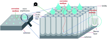
Based on above reported literature, the schematic shown in Fig. 12 was drawn to intuitively describe the anti-corrosion mechanism of self-assembled anodic oxide films with regular binary structure. With regards to the mechanism of the corrosion resistance, it can be attributed to the anodic oxide film worked in coordination with the superhydrophobic surface of Al alloys. Firstly, the superhydrophobic surface can prevent the corrosive anions in aqueous solution from attaching to aluminum substrate. Secondly, although the superhydrophobic surfaces have a good stability, during long-term contact of the superhydrophobic film with a corrosive solution, the wetted area (11.93%) of the surface is subjected to corrosion processes and the corrosion anions get into the pores of the anodic oxidation film. At that time, the barrier layer of anodic oxide films will prevent the corrosive anions from permeating in Al substrate which can also promote the anti-corrosion ability of Al alloys. Remarkable resistance was characteristic of the superhydrophobic films obtained by anodic oxidation and chemical modification. Electrochemical and wetting experiments showed that the protective potential is significantly enhanced. The as-prepared 2024 Al alloys behaves an excellent anti-corrosion performance and shows great potential application in many industrial areas. We attribute this to the synergetic effect between the protective properties of air trapped in a low adhesion superhydrophobic surface and good barrier properties of the barrier layer of anodic oxidation film that retard the corrosive anions, and water molecules.


image file: c5ra25153b-f12.tif
Fig. 12 Schematic of self-assembled anodic oxide films during corrosion process.

5. Conclusions

This paper described the aluminum alloys with excellent anti-corrosion property were fabricated by means of chemical etching, anodic oxidation and self-assembly of PTES. The SEM images indicated that anodic oxidation current densities can successfully manipulate the micro/nano-structure on Al alloys surface. As revealed by the potentiodynamic polarization tests and EIS measurements, the as-prepared PTES-SAMs showed an excellent anti-corrosion capability compared with bare Al alloys because of the anodic oxide layer and their surface superhydrophobicity. Furthermore, the anodic oxidation current density is the critical factor for the surface morphology fabrication and it is important for the anti-corrosion performance. The samples prepared by anodic oxidation current densities of 5 A dm−2 exhibited the best anti-corrosion behavior for its high WCA and low-adhesion than other samples. The results showed in this paper provided an effective protection method for Al alloys, which can prevent future corrosion via anodic oxidation and chemical modification, removing the need for replacement of the whole Al alloys. Through a combination of anodic oxidation films with novel micro/nano-binary structure and chemical modification, Al alloys with excellent anti-corrosion performance were obtained.

Acknowledgements

This work was supported by the National Key Basic Research Program of China (973) (2014CB643305), the National Natural Science Foundation of China (51202263), the Scientific and Technological Innovative Team Project of Zhejiang Province (2011R50006).

References

  1. G. E. Thompson, R. C. Furneaux, G. C. Wood, J. A. Richardson and J. S. Goode, Nature, 1978, 272, 433–435 CrossRef CAS.
  2. M. F. Naeini, M. H. Shariat and M. Eizadjou, J. Alloys Compd., 2011, 509, 4696–4700 CrossRef CAS.
  3. Q. Zhang, Y.-R. Zhu and Z.-Y. Huang, Chem. J. Chin. Univ., 2009, 30, 2210–2214 CAS.
  4. J. Ou, W. Hu, M. Xue, F. Wang and W. Li, ACS Appl. Mater. Interfaces, 2013, 5, 3101–3107 Search PubMed.
  5. D. Kong and J. Wang, J. Alloys Compd., 2015, 632, 286–290 CrossRef CAS.
  6. G. M. Scamans and A. S. Rehal, J. Mater. Sci., 1979, 14, 2459–2470 CrossRef CAS.
  7. C.-C. Tseng, J.-L. Lee, T.-H. Kuo, S.-N. Kuo and K.-H. Tseng, Surf. Coat. Technol., 2012, 206, 3437–3443 CrossRef CAS.
  8. B. Grignard, A. Vaillant, J. de Coninck, M. Piens, A. M. Jonas, C. Detrembleur and C. Jerome, Langmuir, 2011, 27, 335–342 CrossRef CAS PubMed.
  9. Z. G. Guo, F. Zhou, J. C. Hao and W. M. Liu, J. Am. Chem. Soc., 2005, 127, 15670–15671 CrossRef CAS PubMed.
  10. S. M. Li, S. Z. Zhou and J. H. Liu, Acta Phys.-Chim. Sin., 2009, 25, 2581–2589 CAS.
  11. F. Z. Zhang, L. L. Zhao, H. Y. Chen, S. L. Xu, D. G. Evans and X. Duan, Angew. Chem., Int. Ed., 2008, 47, 2466–2469 CrossRef CAS PubMed.
  12. L. Qin, W. Zhao, H. Hou, Y. Jin, Z. Zeng, X. Wu and Q. Xue, RSC Adv., 2014, 4, 60307–60315 RSC.
  13. Y. Liu, J. Liu, S. Li, Y. Wang, Z. Han and L. Ren, Colloids Surf., A, 2015, 466, 125–131 CrossRef CAS.
  14. Z. Chen, M. Shuai and L. Wang, J. Solid State Electrochem., 2013, 17, 2661–2669 CrossRef CAS.
  15. X. Shi, N. Tuan Anh, Z. Suo, J. Wu, J. Gong and R. Avci, Surf. Coat. Technol., 2012, 206, 3700–3713 CrossRef CAS.
  16. K. S. Kim, J. A. Hurtado and H. Tan, Phys. Rev. Lett., 1999, 83, 3872–3875 CrossRef CAS.
  17. R. Wu, S. Liang, A. Pan, Z. Yuan, Y. Tang, X. Tan, D. Guan and Y. Yu, Appl. Surf. Sci., 2012, 258, 5933–5937 CrossRef CAS.
  18. T. Onda, S. Shibuichi, N. Satoh and K. Tsujii, Langmuir, 1996, 12, 2125–2127 CrossRef CAS.
  19. T. Minami, N. Katata and K. Tadanaga, Preparation and characterization of super-water-repellent Al2O3 coating films with high transparency, 1997 Search PubMed.
  20. B. Yin, L. Fang, J. Hu, A. Q. Tang, J. He and J. H. Mao, Surf. Interface Anal., 2012, 44, 439–444 CrossRef CAS.
  21. D. Najjar, T. Magnin and T. J. Warner, Mater. Sci. Eng., 1997, 238, 293–302 CrossRef.
  22. W. L. Zhang and G. S. Frankel, Electrochim. Acta, 2003, 48, 1193–1210 CrossRef CAS.
  23. V. Moutarlier, M. P. Gigandet, B. Normand and J. Pagetti, Corros. Sci., 2005, 47, 937–951 CrossRef CAS.
  24. S.-M. Li, S.-Z. Zhou and J.-H. Liu, Acta Phys.-Chim. Sin., 2009, 25, 2581–2589 CAS.
  25. L. Feng, Y. Che, Y. Liu, X. Qiang and Y. Wang, Appl. Surf. Sci., 2013, 283, 367–374 CrossRef CAS.
  26. Z. Li, Y. Yuan and X. Jing, J. Alloys Compd., 2012, 541, 380–391 CrossRef CAS.
  27. W. Chen, J.-S. Wu and X.-H. Xia, ACS Nano, 2008, 2, 959–965 CrossRef CAS PubMed.
  28. K. Schwirn, W. Lee, R. Hillebrand, M. Steinhart, K. Nielsch and U. Goesele, ACS Nano, 2008, 2, 302–310 CrossRef CAS PubMed.
  29. O. Jessensky, F. Muller and U. Gosele, Appl. Phys. Lett., 1998, 72, 1173–1175 CrossRef CAS.
  30. L. B. Boinovich, A. M. Emelyanenko, A. D. Modestov, A. G. Domantovsky and K. A. Emelyanenko, ACS Appl. Mater. Interfaces, 2015, 7, 19500–19508 Search PubMed.
  31. F. Zhang, S. Chen, L. Dong, Y. Lei, T. Liu and Y. Yin, Appl. Surf. Sci., 2011, 257, 2587–2591 CrossRef CAS.
  32. A. Ulman, Chem. Rev., 1996, 96, 1533–1554 CrossRef CAS PubMed.
  33. O. P. Khatri, D. Devaprakasam and S. K. Biswas, Tribol. Lett., 2005, 20, 235–246 CrossRef CAS.
  34. S. Akiya, T. Kikuchi, S. Natsui and R. O. Suzuki, J. Electrochem. Soc., 2015, 162, E244–E250 CrossRef CAS.
  35. S. Ono, M. Saito and H. Asoh, Electrochim. Acta, 2005, 51, 827–833 CrossRef CAS.
  36. Y. Kihn, G. E. Thompson, G. Galaup, P. Skeldon, X. Zhou, K. Shimizu and H. Habazaki, Corros. Sci., 2000, 42, 533–544 CrossRef CAS.
  37. R. V. Lakshmi and B. J. Basu, J. Colloid Interface Sci., 2009, 339, 454–460 CrossRef CAS PubMed.
  38. L. Gao and T. J. McCarthy, J. Am. Chem. Soc., 2006, 128, 9052–9053 CrossRef CAS PubMed.
  39. S. Banerjee, A. Mishra, M. M. Singh, B. Maiti, B. Ray and P. Maiti, RSC Adv., 2011, 1, 199–210 RSC.
  40. M. M. Verdian, K. Raeissi and M. Salehi, J. Alloys Compd., 2010, 507, 42–46 CrossRef CAS.
  41. D. Colorado-Garrido, D. M. Ortega-Toledo, J. A. Hernandez, J. G. Gonzalez-Rodriguez and J. Uruchurtu, J. Solid State Electrochem., 2009, 13, 1715–1722 CrossRef CAS.
  42. M. Ates and N. Uludag, J. Appl. Polym. Sci., 2012, 124, 4655–4662 CAS.

This journal is © The Royal Society of Chemistry 2016
Click here to see how this site uses Cookies. View our privacy policy here.