Recycling and synthesis of LiNi1/3Co1/3Mn1/3O2 from waste lithium ion batteries using D,L-malic acid

Lu Yao*ab, Haisen Yaoc, Guoxi Xi*a and Yong Fenga
aKey Laboratory for Yellow River and Huai River Water Environment and Pollution Control, Ministry of Education, School of Environment, Henan Normal University, Xinxiang 453007, PR China. E-mail: yaolu1020@126.com; yaolu001@163.com; Fax: +86 373 3326336; Tel: +86 373 3325796 Tel: +86 139 37399599
bSchool of Chemistry and Chemical Engineering, Xinxiang University, Xinxiang 453007, PR China
cCOSL Drilling Pan-Pacific Ltd, Temasek Boulevard Penthouse Level Suite 2, Suntec Tower Four, 038986, Singapore

Received 26th November 2015 , Accepted 27th January 2016

First published on 29th January 2016


Abstract

If waste LIBs are disposed of in landfill sites, soil contamination will ensue from leakage of the organic electrolyte, and the heavy metals ions contained in the batteries would pose a threat to the environment. A new process for recycling valuable metal ions from waste lithium-ion batteries (LIBs) is introduced herein. D,L-malic acid was used as both a leaching reagent and chelating agent. By adjusting the metal ion ratio and pH of leachate, a new cathode material of LiNi1/3Co1/3Mn1/3O2 for lithium ion batteries through a sol–gel process without other chelating reagents was synthesized. Electrochemical tests showed the initial charge and discharge capacity of the regenerated material to be 152.9 mA h g−1 and 147.2 mA h g−1 (2.75–4.25 V, 0.2C), respectively. The capacity retention at the 100th cycle remains 95.06% of the original value (2.75–4.25 V, 0.5C). Results indicated that the LiNi1/3Co1/3Mn1/3O2 produced from waste LIBs possessed good electrochemical properties.
1. Introduction

Lithium ion batteries (LIBs) are widely used as electrochemical power sources in electronic equipment and electric vehicles (EV). Their desirable characteristics such as safe handling, good cycle performance, lower self-discharge rate, significantly higher energy density and higher voltage have made LIBs preferable to typical nickel-cadmium (Ni–Cd) or nickel–metal hydride (Ni–MH) batteries.1,2 Therefore the LIBs have been progressively introduced on the consumer market, and the market share has increased year by year. World LIB production reached 500 million units in 2000 and almost 4.6 billion in 2010.3 In 2014, the production of LIBs in China had reached 5.287 billion units. The greater number of LIBs being produced means that more waste LIBs will need to be recycled. Waste LIBs contain large amounts of valuable metals. The metal content is normally even higher than natural ores. Meanwhile, they are recognized as typical hazardous solid waste due to toxic metals and corrosive electrolytes.4,5 If waste LIBs are disposed of in landfill sites, soil contamination will ensue from leakage of the organic electrolyte, and the heavy metals contained in the batteries would pose a threat to the environment. From the viewpoints of environmental preservation and recovery of valuable resources, the recycling of spent lithium ion batteries is highly desirable. Hence, finding an effective way of recovering the valuable metals and preventing pollution from LIBs have become a global issue.

Recycling of waste batteries has aroused widespread interest in recent years. Global researchers have developed many processes on the recycling the waste LIBs with the first commercial cathode material of LiCoO2, and many processes have been proposed for recycling cobalt and lithium from LiCoO2 active materials.6–10 The current recycling processes for waste LIBs have been reviewed by Xu et al.11,12 The overall recycling process includes two basic classes: physical processes and chemical processes. Physical processes often associate the pre-treatment processes, such as crushing, sieving and separation of materials to separate the cathode materials from the case, collector and anode active materials. The chemical process can be summarized as pyrometallurgy,13 biometallurgy,7,14 hydrometallurgy.15–17 Pyrometallurgical processes are often accompanied by high gas emissions and have high energy consumption, so they require stringent air filtration standards and high equipment investment. The biometallurgy process has many attracting virtues such as high efficiency, low cost and the modest apparatus needed. But the long treatment period and the difficult incubation of bacteria restrict the popularization of this process. So the most well-established process is the hydrometallurgy. The hydrometallurgy process often started with the acid leaching, employing dilute H2SO4,5,10 HNO3,8,18 HCl,19 or even mixed acid to dissolve the cathode material.

LIBs consist of cathode electrode, anode electrode, organic electrolyte and separator. LiCoO2, LiMn2O4, LiNi1/3Co1/3Mn1/3O2 and LiFePO4 are the main cathode materials for almost all commercial LIBs.20 The traditional layered LiCoO2 cathode material suffers from the shortcomings such as high cost, safety hazards and environmental toxicity.21 The LiNi1/3Co1/3Mn1/3O2 (LNCM in the following), as they possesses a high discharge capacity, moderate voltage range and the resultant high energy density, has been considered as a promising cathode candidates in recent years.22,23The market share of the LNCM has been increased year by year. Cobalt, nickel and manganese are extremely similar in chemical property. The traditional process of separation from each other is difficult in this system. Weng et al.24 reported a process for recycling spent LIBs and prepared Li[(Ni1/3Co1/3Mn1/3)1−xMgx]O2. The recycling process consisted of thermal treatment, crushing, ball-milling, sieving, alkali leaching, sulfuric acid leaching, Na2S precipitation, D2EHPA solvent extraction, and at last, compound of NiSO4, CoSO4 and MnSO4 were recovered one by one as the final products by organic solvent extraction, the final cathode material was produced by solid-state calcination. The process is complex, and the reagent used in this system requires high equipment investment and the separation and purification process would produce second pollution. Xihua Zhang et al.25 tried to separating the cathode scraps which have not experienced the multiple charge–discharge cycles, and found that trifluoroacetic acid (TFA) can effectively remove LNCM from Al foil and resynthesized LNCM with solid state method. Francesca Pagnanelli et al.26,27 found that glucose and organic acid could reduce or dissolve the cobalt ions from LiCoO2.

In this paper, a novel recycling technology to regenerate LNCM as new lithium ion cathode material from exhausted LIBs was developed. D,L-Malic acid is inexpensive and non-hazardous. Li. et al. reported that it could leach lithium ion and cobalt ion effectively from the LiCoO2 of waste LIBs,26 but the recycling waste LNCM from waste lithium ion batteries with D,L-malic acid has not been reported. As for D,L-malic acid could offer H+ for the acid leaching process and carboxyl groups for the subsequent chelating process. In this study, we have recycled waste LIBs with LNCM as cathode active materials through an environmentally friendly process involving D,L-malic acid, which avoids complicated metal ion separation procedures. Moreover, a cathode material, LiNi1/3Co1/3Mn1/3O2, with good electrical property has been synthesized by a very simple method.

2. Experimental

2.1 Materials and reagents

The spent LIBs with LNCM as cathode material used in our study were kindly donated by Henan Huanyu Group (Xinxiang, China), D,L-malic acid was used as leaching agent and the chelating reagent in the process. Hydrogen peroxide (H2O2) was employed as a reductive reagent. All other reagents used in this study were analytical grade, and the solutions were prepared with specified concentration in distilled water.

2.2 Experimental procedure

The spent LIBs were firstly discharged with resistance to prevent short-circuiting and self-ignition, then dismantled manually into different components with appropriate safety precautions. Separated the cathode electrode and cut into small pieces with a certain length and placed into the vacuum furnace,28 heated to 600 °C with a heating rate of 5 °C min−1, and held at the desired temperature for 2 h. Cooled to room temperature and then the active materials were peeled from aluminum foils for the following experiments.

An overall recycling route proposed to treat spent LIBs is shown in Fig. 1


image file: c5ra25079j-f1.tif
Fig. 1 The flowchart of the whole process for the recycling of the used lithium ion battery.

The hydrometallurgical leaching experiments were carried out in a glass breaker, which was placed in a water bath to control the reaction temperature. The reactor was fitted with a magnetic stirring apparatus. 3.0 g waste LNCM was dissolved in 50 mL 1.0 mol L−1 D,L-malic acid solution. To accelerate the leaching efficiency, 3 mL H2O2 was added into the system. The temperature was kept at 50 °C for 30 min. The concentrations of lithium, nickel, cobalt, and manganese ions in the leachate were determined by inductively coupled atomic emission spectrometry (ICP-AES). The molar ratio of these metal ions was adjusted to =1.05[thin space (1/6-em)]:[thin space (1/6-em)]0.33[thin space (1/6-em)]:[thin space (1/6-em)]0.33[thin space (1/6-em)]:[thin space (1/6-em)]0.33, and the metals concentration with 1.0 mol L−1 by adding the corresponding metal nitrate, and the pH was adjusted to 8.0 by adding a suitable amount of aqueous ammonia. The solution was heated at 80 °C in a water bath to obtain a transparent gel, which was then dried at 110 °C in an oven for 24 h. The dried gel was preheated at 400 °C for 2 h in the ambient atmosphere for the decomposition of the organic compounds. After cooling to room temperature, the precursor mixture was ground again and heated at 650–950 °C for 2–8 h. For comparison, fresh-LNCM was synthesized with the same process with the metal nitrates as starting materials, which was denoted as FLNCM.

2.3 Characterizations and evaluation of electrochemistry activity

In order to analyze and adjust the concentration of the Li, Ni, Co and Mn metal ions, a Perkin Elmer ICP-OES (model Optima 2100DV, America) was used. X-ray diffraction (XRD) patterns of the product synthesized from the waste LIBs were collected on a Bruker X-ray diffraction with Cu Kα radiation (model BRUKER.axs, Germany) at 40 kV/40 mA, within 10–90° 2θ-theta range. Evaluation of the thermogravimetric analysis/differential scanning calorimetry (TG-DSC) (model STA-449 F3, Germany) at a heating rate of 10 °C min−1 in a static air. Fourier transform infrared spectroscopy (FT-IR) was recorded on a Bruker spectrometer in the range of 400–4000 cm−1 using the KBr pellet method (model Tensor 27, Bruker). The microstructure of the refreshed powder was observed using a field emission scanning electron microscope (FESEM) (model SUPRA 40).

The electrochemical performance was evaluated by using laboratory half-cells CR2016-type coin cells. The coin-type cells were assembled and sealed in a dry and argon-filled glove box. For the cathode assembly, the LNCM powders were thoroughly mixed with PVDF as a binder and two conducting media (Super-P and KS-6) at a weight ratio of 80[thin space (1/6-em)]:[thin space (1/6-em)]10[thin space (1/6-em)]:[thin space (1/6-em)]5[thin space (1/6-em)]:[thin space (1/6-em)]5 in NMP solvent to form the electrode slurry, which was pasted on an Al foil. The solvent was evaporated, and the prepared cathode sheets were dried in vacuum. Coin cells were then assembled in a glove box for electrochemical characterization. In the test cells, Li foil and a porous polypropylene film served as the counter electrode and the separator, respectively. The electrolyte was 1.0 mol L−1 LiPF6 in a mixture of ethylene carbonate, polycarbonate, and dimethyl carbonate with a weight ratio of 1[thin space (1/6-em)]:[thin space (1/6-em)]1[thin space (1/6-em)]:[thin space (1/6-em)]1. Charge/discharge tests were performed at 0.2C (30 mA) at room temperature in the voltage range 2.75–4.25 V.

3. Results and discussion

3.1 Leaching mechanism of the waste LNCM

The main metal ions in the waste LNCM are Li+, Co2+, Co3+, Ni2+, Ni3+, Ni4+, and Mn4+.29 Of these, Li+ and divalent metal ions may be readily leached by the acid, but high valent metal ions would not be easily leached without a reducing agent. There are many literatures show that hydrogen peroxide (H2O2), can reduce high-valent transition metal ions to low valent state.2,26,30 It is beneficial to deploy a reducing agent along with leaching acids. H. Zou et al. found that waste LiNi1/3Co1/3Mn1/3O2 could be dissolved in 4 mol L−1 sulfuric acid with 30 wt% H2O2, and the leaching equation was as follows:31
6LiNi0.33Mn0.33Co0.33O2 + 9H2SO4 + H2O2 = 2MnSO4 + 2NiSO4 + 2CoSO4 + 3Li2SO4 + 2O2 + 10H2O

In this system, H2O2 serves as a reductant, Ni4+ serves as an oxidant,

ΦΘNi4+/Ni2+ = 1.678 V, ΦΘO2/H2O2 = 0.699 V, ΔEΘ = ΦΘNi4+/Ni2+ΦΘO2/H2O2 = 0.979 V,

log[thin space (1/6-em)]K = nΔEΘ/0.059 = 33, K = 1033.

The stability constant K is sufficiently high and this redox reaction could proceed effectively. Similarly,

ΦΘMn4+/Mn2+ = 1.224,

ΔEΘ = ΦΘMn4+/Mn2+ΦΘO2/H2O2 = 0.525 V, log[thin space (1/6-em)]K = nΔEΘ/0.059 = 17.8, K = 1017.8.

ΦΘCo3+/Co2+ = 1.83, ΔEΘ = ΦΘCo3+/Co2+ΦΘO2/H2O2 = 1.131 V, log[thin space (1/6-em)]K = nΔEΘ/0.059 = 19.2, K = 1019.2.
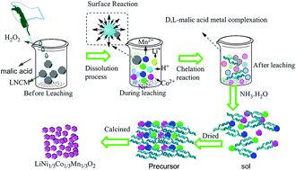
So, H2O2 can accelerate the leaching rates and efficiency. Thus the dissolution of high valent ions follows a reduction-complex mechanism: M3+/4+}oxide + H+ + H2O2 → M2+}oxide → M2+}(aq.) →M(II)–malic, (where M represents either nickel, cobalt or manganese).32 Such a heterogeneous reaction is expected to occur at the interface of solid (oxide lattice) and liquid.33

The schematic illustration of the leaching and complexing process is as follows: (Fig. 2)


image file: c5ra25079j-f2.tif
Fig. 2 Schematic illustration of the leaching of LNCM and the coordination of the metal ions with D,L-malic acid.

3.2 TG/DSC curves of the dried gel

The thermal behavior of the obtained LNCM precursor is analyzed using simultaneous TG/DSC measurements. The TG-DSC curves of the dried gel are shown in Fig. 3. The TG curve shows a multistep weight loss, and there is also an endothermic trough and one exothermic peak in the DSC curves. The initial weight loss of 5.19% and 22.44% with an endothermic trough, which were due to a dehydration of absorbed water and the decomposition of the D,L-malic acid. The strong exothermic peak at 391 °C with a large weight loss with 47.88% is due to the decomposition of the dried gels. Only a small amount of weight loss is observed in the TG curve which becomes smooth and flat in the temperature range from 400 to 1000 °C. So, the pre-calcined temperature was chosen as 400 °C.
image file: c5ra25079j-f3.tif
Fig. 3 TG/DSC curves of the dried gel.

3.3 Characterization of re-synthesized LNCM

The XRD patterns of the re-synthesized LNCM materials calcined at different temperature was shown in Fig. 4a. All the samples had the layered structure without any impurity reflections, and all the peaks could be indexed to the hexagonal α-NaFeO2 crystal structure with a space group of R3m. With the increase of the calcined temperature, the intensity of the peaks increased and the peaks become sharper and better-defined. The sharp and well-defined diffraction peaks indicated good crystallization. The clear splitting of the hexagonal doublets (006/102) around 38° and the (108)/(110) around 65° observed for the samples calcined at 850 °C and 950 °C, indicating the highly ordered layered structure of LiNi1/3Co1/3Mn1/3O2.34,35
image file: c5ra25079j-f4.tif
Fig. 4 XRD patterns and IR spectroscopy of the resynthesized LNCM (a and c) calcined at different temperature for 4 h, (b) calcined for different time at 850 °C.

As many literatures reports, higher c/a value (c/a > 4.9) indicates the well-defined hexagonal layered structure.36 The intensity ratio of the (0 0 3) to (1 0 4) peaks in the XRD patterns could be used to identify the cation mixing extent of layered structure.37 Generally, the undesirable cation mixing would take place when the integrated intensity ratio is less than 1.2. The lattice parameters of LNCM prepared with various calcination temperatures are summarized in Table 1. When the calcination temperature is not higher than 850 °C, the values of c/a and I(003)/I(104) increase with increasing calcination temperature. However, the values of c/a and I(003)/I(104) decrease when the calcination temperature is increased to 950 °C. According to the above results, the sample calcined at 850 °C exhibits the best layered structure and the lowest cation mixing.

Table 1 Lattice parameters of LNCM prepared with various calcination temperatures
Sample a c c/a I(003)/I(104)
R-LNCM-650 2.859 14.210 4.970 1.119
R-LNCM-750 2.857 14.222 4.978 1.212
R-LNCM-850 2.862 14.250 4.979 1.589
R-LNCM-950 2.864 14.246 4.974 1.565


Fig. 4b shows the XRD patterns of the re-synthesized LNCM calcined at 850 °C for different time. When calcined for 2 h, the splitting of the hexagonal doublets (006/102) around 38° and the (108)/(110) around 65° is not observed. With the increase of the calcined time, the peaks become sharper and the splitting of the hexagonal doublets is more obvious, indicating the good crystalline of the resynthesized material. So the precursors were calcined the precursor at 850 °C for 8 h in the following experiments.

Fig. 4c shows the FTIR spectra of the synthesized LNCM samples calcined at 750–950 °C. Three samples possess the similar spectroscopy. The dominant absorption bands at around 592 cm−1 were assigned to the asymmetric stretching vibration of transition metal oxide (MO6), and the absorption bands at around 542 cm−1 was assigned to the bending vibrations (O–M–O).38,39 Broad band observed around 1633 cm−1 and 3440 cm−1 indicate the presence of bending (O–H) vibration for adsorbed H2O in the materials based on perfect agreement with literature reports.40 Thereby confirms the chemical integrity of the intended LNCM.

The effect of calcined temperatures on the morphologies of resynthesized LNCM was observed by FESEM. The Fig. 5a–f illustrated the micrographs of the resynthesized LNCM and the FLNCM calcined at different temperature, respectively. From the FESEM images, the resynthesized LNCM at 650 °C and 750 °C is irregular for their not good crystalline structure. The product calcined at 850 °C and 950 °C has regular structure, and the particle size increased dramatically with the increased of the temperature.


image file: c5ra25079j-f5.tif
Fig. 5 (a–d) are the FESEM image of the resynthesized LNCM calcined at different temperature for 6 h in air (a: 650 °C, b: 750 °C, c: 850 °C, d: 950 °C), (e) and (f) are the FLNCM calcined at 850 and 950 °C.

The LNCM-850 possessed faceted, edge-blunted polyhedral morphology structure. The FLNCM has the similar morphology structure. Particle with this shape is beneficial for the capacity enhancement due the larger radius of curvature than spherical particles which is helpful to the good electrochemical structure.41 The LNCM-950 possessed regular octahedral structure and the particle size increased significantly. Chen Zhanjun et al. found that octahedral structure was not as good as the chamfered polyhedral structure.42

EDS (energy dispersive X-ray detector spectroscopy) was used to verify the distribution of the 3d metals in the obtained materials. As shown in Fig. 6, all the materials are composed of Co, Ni, Mn and O species and the elements were uniformly distributed; Li cannot be detected for its low energy density. It can be seen that the molar ratios of the elements Ni, Co, and Mn were approximately the same as the theoretical values of 1[thin space (1/6-em)]:[thin space (1/6-em)]1[thin space (1/6-em)]:[thin space (1/6-em)]1, meaning that our synthesized samples were prepared with good stoichiometry.


image file: c5ra25079j-f6.tif
Fig. 6 The EDS image of LNCM materials prepared from waste LNCM by D,L-malic acid-assisted sol–gel method.

3.4 Electrochemical studies

Fig. 7 shows charge and discharge of the LNCM before and after recycled. The charge and discharge specific capacities of the exhausted LNCM were only 53 and 52.5 mA h g−1, respectively. While the charge and discharge specific capacity of resynthesized LNCM can reach 152.9 and 147.2 mA h g−1. The discharge capacity has enhanced dramatically.
image file: c5ra25079j-f7.tif
Fig. 7 The charge and discharge curves of the LNCM before and after recycled.

Fig. 8a and b shows the initial charge–discharge curves and cycling performance at room temperature of the resynthesized LNCM calcined at the three temperatures. All charge–discharge curves had a potential plateau at 3.6–3.8 V in agreement with typical layer structured LNCM. The initial specific discharge capacities at 0.5C in 2.75–4.25 V were 147.2, 134.5, and 118.8 mA h g−1, while the discharge capacities decreased to 139.0, 118.2 and 96 mA h g−1 after 100 cycles with related capacity retention of 94.4%, 87.9%, and 80.8% for samples calcined at 850 °C, 950 °C and 750 °C, respectively. Among all the samples, sample LNCM-850 has the highest discharge capacity and best cycling performance. These results are consistent with the XRD results. As for the FLNCM synthesized from nitrate metals, and the initial specific discharge capacities at 0.5C were 150.1, 146.8 and 127.2 mA h g−1 respectively. After 100 cycles, the specific capacity decreased to 143.6, 131.7, 103.4 mA h g−1 with capacity retention of 95.4%, 90.2% and 81.4% for samples calcined at different temperature. The FLNCM850 and FLNCM 950 shows better cycling performance and higher discharge capacity. The performance of resynthesized LNCM is almost as good as the fresh synthesized LNCM. Fig. 8c and d shows the charge–discharge curves at different cycles and the cycle performance of the FLNCM.


image file: c5ra25079j-f8.tif
Fig. 8 The charge–discharge curves and cycle performance of LNCM and FLNCM synthesized by different calcination temperature. (a and b) Initial charge–discharge curves and cycle performance; (c and d): cycle performance for FLNCM and the curves of FLNCM850 for 1st, 2nd, 3rd, 10th, 30th, 50th, 80th, 100th.

Rate capability is another very important consideration for practical Li-ion batteries. To evaluate the rate performance of the LNCM electrodes, charge–discharge measurements were conducted at stepwise currents varied from 0.2C to 5C, and back to 0.2C. As shown in Fig. 9a and b, the LNCM-850 electrode illustrates a stable discharge capacity, even at high current rates (e.g. >120 mA h g−1 at 2C, >100 mA h g−1 at 5C), whereas LMNC-750 exhibits a drastic fall at high current rates (e.g. <100 mA h g−1 at 2C, <70 mA h g−1 at 5C). Returning to the low current rate of 0.2C, it is observed that the capacity of the LNCM electrode can be properly restored (e.g. >140 mA h g−1). The cycle plots and the charge/discharge curves of FLNCM for different cycles were listed in Fig. 9c. The FLNCM from pure material shows the similar trend as the resynthesized LNCM.


image file: c5ra25079j-f9.tif
Fig. 9 The rate performance at various current densities from 0.2C to 5C (1C = 140 mA h g−1).

To understand the enhanced rate capability, resistance was analyzed by electrochemical impedance spectroscopy (EIS). Nyquist plots of the three samples are shown in Fig. 10, and the Nyquist plots were analyzed by fitting to an equivalent electrical circuit as shown in the inset of Fig. 10. The Nyquist plots of all three electrodes depict a semicircle at high-medium frequency and an inclined line at low frequency. The components of the equivalent circuit include: the high frequency intercepts with the Z′-axis represent electrolyte resistance and electronic resistance of the electrode Rs as the ohmic resistance (total resistance of the electrolyte, separator, and electrical contacts), the semicircle at medium frequency is usually assigned to the charge transfer impedance and capacitance electrochemical reaction at the electrode surface Rct as the charge transfer resistance, ZW as the Warburg impedance of Li ion diffusion into the active materials, and CPE is the constant phase-angle element which involves the double layer capacitance.43,44 The transfer resistances (Rct) of LNCM-750, LNCM-850, and LNCM-950 electrodes are 160.2, 61.5, and 106.1 ohm, respectively. This suggests that the LNCM-850 has the lowest activation energy for the Li+ diffusion and undergo a fast faradaic reaction, which supports the increased high-rate performance of the LNCM-850 in comparison to the other two electrodes.


image file: c5ra25079j-f10.tif
Fig. 10 Comparison of EIS plots of the LNCM calcined with different temperature with an equivalent circuit (inset).

4. Conclusion

In summary, with D,L-malic acid as the leaching agent and chelating agent, we designed a facile in situ route by using waste lithium ion battery as raw material to synthesized uniform LiNi1/3Co1/3Mn1/3. The recycling process avoids complicated separation of the metal ions and produces minimal pollution and side products. The recovered and reconstituted cathode material showed high specific capacity and good electrochemical cycling properties, which can meet the requirements for the manufacture of new LIBs.

Acknowledgements

This study was supported by National Science Foundation of China (No. 51174083). It also was supported by Specialized Research Fund for the Doctoral Program of Higher Education (No. 20114104110004).

References

  1. R.-C. Wang, Y.-C. Lin and S.-H. Wu, Hydrometallurgy, 2009, 99, 194–201 CrossRef CAS.
  2. L. Chen, X. Tang, Y. Zhang, L. Li, Z. Zeng and Y. Zhang, Hydrometallurgy, 2011, 108, 80–86 CrossRef CAS.
  3. L. Li, J. B. Dunn, X. X. Zhang, L. Gaines, R. J. Chen, F. Wu and K. Amine, J. Power Sources, 2013, 233, 180–189 CrossRef CAS.
  4. S. M. Shin, N. H. Kim, J. S. Sohn, D. H. Yang and Y. H. Kim, Hydrometallurgy, 2005, 79, 172–181 CrossRef CAS.
  5. M. K. Jha, A. Kumari, A. K. Jha, V. Kumar, J. Hait and B. D. Pandey, Waste Manage., 2013, 33, 1890–1897 CrossRef CAS PubMed.
  6. G. Zeng, X. Deng, S. Luo, X. Luo and J. Zou, J. Hazard. Mater., 2012, 199–200, 164–169 CrossRef CAS PubMed.
  7. B. Xin, D. Zhang, X. Zhang, Y. Xia, F. Wu, S. Chen and L. Li, Bioresour. Technol., 2009, 100, 6163–6169 CrossRef CAS PubMed.
  8. L. Li, R. Chen, F. Sun, F. Wu and J. Liu, Hydrometallurgy, 2011, 108, 220–225 CrossRef CAS.
  9. L. Sun and K. Qiu, Waste Manage., 2012, 32, 1575–1582 CrossRef CAS PubMed.
  10. L. Ma, Z. Nie, X. Xi and X. g. Han, Hydrometallurgy, 2013, 136, 1–7 CrossRef CAS.
  11. D. Lisbona and T. Snee, Process Saf. Environ. Prot., 2011, 89, 434–442 CrossRef CAS.
  12. J. Xu, H. R. Thomas, R. W. Francis, K. R. Lum, J. Wang and B. Liang, J. Power Sources, 2008, 177, 512–527 CrossRef CAS.
  13. J. F. Paulino, N. G. Busnardo and J. C. Afonso, J. Hazard. Mater., 2008, 150, 843–849 CrossRef CAS PubMed.
  14. D. Mishra, D.-J. Kim, D. E. Ralph, J.-G. Ahn and Y.-H. Rhee, Waste Manage., 2008, 28, 333–338 CrossRef CAS PubMed.
  15. J. Lemaire, L. Svecova, F. Lagallarde, R. Laucournet and P.-X. Thivel, Hydrometallurgy, 2014, 143, 1–11 CrossRef CAS.
  16. B. Swain, J. Jeong, K. Yoo and J.-c. Lee, Hydrometallurgy, 2010, 101, 20–27 CrossRef CAS.
  17. L. Jiang, L. Huang and Y. Sun, Int. J. Hydrogen Energy, 2014, 39, 654–663 CrossRef CAS.
  18. Q. Y. Li Yang, G. Xi, L. Niu, T. Lou, T. Wang and X. Wang, J. Mater. Sci., 2011, 46, 6106–6110 CrossRef.
  19. M. Joulie, R. Laucournet and E. Billy, J. Power Sources, 2014, 247, 551–555 CrossRef CAS.
  20. K. Du, J. Huang, Y. Cao, Z. Peng and G. Hu, J. Alloys Compd., 2013, 574, 377–382 CrossRef CAS.
  21. A. Mahmoud, I. Saadoune, J. M. Amarilla and R. Hakkou, Electrochim. Acta, 2011, 56, 4081–4086 CrossRef CAS.
  22. J. Li, S. Xiong, Y. Liu, Z. Ju and Y. Qian, Nano Energy, 2013, 2, 1249–1260 CrossRef CAS.
  23. A. Mahmoud, I. Saadoune, J. M. Amarilla and R. Hakkou, Electrochim. Acta, 2011, 56, 4081–4086 CrossRef CAS.
  24. Y. Weng, S. Xu, G. Huang and C. Jiang, J. Hazard. Mater., 2013, 246–247, 163–172 CrossRef CAS PubMed.
  25. X. Zhang, Y. Xie, H. Cao, F. Nawaz and Y. Zhang, Waste Manage., 2014, 34, 1715–1724 CrossRef PubMed.
  26. L. Li, J. Ge, R. Chen, F. Wu, S. Chen and X. Zhang, Waste Manage., 2010, 30, 2615–2621 CrossRef CAS PubMed.
  27. F. Pagnanelli, E. Moscardini, G. Granata, S. Cerbelli, L. Agosta, A. Fieramosca and L. Toro, J. Ind. Eng. Chem., 2014, 20, 3201–3207 CrossRef CAS.
  28. L. Sun and K. Qiu, J. Hazard. Mater., 2011, 194, 378–384 CrossRef CAS PubMed.
  29. L. Yao, Y. Feng and G. Xi, RSC Adv., 2015, 5, 44107–44114 RSC.
  30. D. A. Ferreira, L. M. Z. Prados, D. Majuste and M. B. Mansur, J. Power Sources, 2009, 187, 238–246 CrossRef CAS.
  31. H. Zou, E. Gratz, D. Apelian and Y. Wang, Green Chem., 2013, 15, 1183–1191 RSC.
  32. G. P. Nayaka, J. Manjanna, K. V. Pai, R. Vadavi, S. J. Keny and V. S. Tripathi, Hydrometallurgy, 2015, 151, 73–77 CrossRef CAS.
  33. K.-M. Nam, H.-J. Kim, D.-H. Kang, Y.-S. Kimb and S.-W. Song, Green Chem., 2015, 17, 1127–1135 RSC.
  34. X. Liu, P. He, H. Li, M. Ishida and H. Zhou, J. Alloys Compd., 2013, 552, 76–82 CrossRef CAS.
  35. F. Wang, S. Xiao, Z. Chang, Y. Yang and Y. Wu, Chem. Commun., 2013, 49, 9209–9211 RSC.
  36. S. Zhang, C. Deng, B. L. Fu, S. Y. Yang and L. Ma, Powder Technol., 2010, 198, 373–380 CrossRef CAS.
  37. J. Chen, N. Zhao, G.-D. Li, F.-F. Guo, J. Zhao, Y. Zhao, T. Jia, F. Fua and J. Lia, Mater. Res. Bull., 2016, 73, 192–196 CrossRef CAS.
  38. P. Manikandan and P. Periasamy, Mater. Res. Bull., 2014, 50, 132–140 CrossRef CAS.
  39. X. Liu, H. Li, D. Li, M. Ishida and H. Zhou, J. Power Sources, 2013, 243, 374–380 CrossRef CAS.
  40. X. Lv, S. Chen, C. Chen, L. Liu, F. Liu and G. Qiu, Solid State Sci., 2014, 31, 16–23 CrossRef CAS.
  41. P. Manikandan, P. Periasamy and R. Jagannathan, J. Power Sources, 2014, 245, 501–509 CrossRef CAS.
  42. Z. Chen, R. Zhao, P. Du, H. Hu, T. Wang, L. Zhu and H. Chen, J. Mater. Chem. A, 2014, 2, 12835 CAS.
  43. M. Wang, G. Lei, J. Hu, K. Liu, S. Sang and H. Liu, RSC Adv., 2014, 4, 62615–62620 RSC.
  44. J. Zhang, Z. Wu, W. Hua, H. Liu and B. Zhong, Ionics, 2015, 21, 3151–3158 CrossRef CAS.

This journal is © The Royal Society of Chemistry 2016
Click here to see how this site uses Cookies. View our privacy policy here.