Yang Zhaoac,
Shuo Wanga,
Chunyan Lia,
Xianbo Yua,
Chunling Zhub,
Xitian Zhangc and
Yujin Chen*a
aKey Laboratory of In-Fiber Integrated Optics, Ministry of Education, College of Science, Harbin Engineering University, Harbin 150001, China. E-mail: chenyujin@hrbeu.edu.cn; Fax: +86-451-82519754; Tel: +86-451-82519754
bCollege of Materials Science and Chemical Engineering, Harbin Engineering University, Harbin 150001, China
cKey Laboratory for Photonic and Electronic Bandgap Materials, Ministry of Education, School of Physics and Electronic Engineering, Harbin Normal University, Harbin 150025, China
First published on 14th January 2016
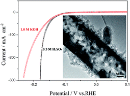
Porous or tubular electrocatalyst with a high surface area is highly desired for hydrogen evolution reaction (HER). Herein we designed and fabricated nanostructured molybdenum phosphide/N,P dual-doped carbon nanotube as electrocatalyst for HER. The electrocatalyst has a high specific surface area of 93.0 m2 g−1 and a big pore volume of 0.42 cm3 g−1, which exhibit good activity toward HER both in acidic and alkaline solutions. To drive cathodic current densities of 1 and 10 mA cm−2, the catalyst only requires overpotentials of 63 and 116 mV vs. RHE in 0.5 M H2SO4 solution, respectively, greatly smaller than those of most of catalysts reported previously. Even in 1.0 M KOH solution, to achieve the same cathodic current densities, the catalyst needs overpotentials of 62 and 117 mV vs. RHE, respectively, also smaller than those of most of catalysts reported previously. Furthermore, the catalyst exhibits excellent long-term stability for HER both in acidic and alkaline solutions. Therefore, the present strategy may open a way for the development of highly active nonprecious catalysts for the HER.
It is well known that the conductivity of electrocatalysts also plays an important role in their catalytic activity besides the number of the active sites.15–20 High conductivity of the electrocatalysts favors in charge-transfer kinetics of HER process, leading to their good catalytic activity toward HER. Incorporating electrocatalysts with conductive supporting materials is one efficient way to improve their conductivity.17,19,21–24 Carbonaceous materials such as carbon black, carbon nanotube (CNT) and graphene etc., are common used as conducting supports due to their good conductivities and excellent chemical stability.21–24 However, they are almost inert for HER. Recent results showed that heteroatom doping could improve the catalytic activities of carbonaceous materials.24–27 For example, N and P dual-doped graphene exhibited significantly enhanced catalytic activity toward HER in both acidic and alkaline solutions compared to single atom-doped graphene or graphene without any atom doping.25 Cobalt-embedded N-rich CNTs showed excellent catalytic activity toward HER due to N doping and concomitant structural defects.26,27 In addition, the introduction of heteroatoms in electrocatalysts also could improve their HER activity.28,29 Thus, the introduction of heteroatoms or heteroatom doping may open a way to design and fabricate good electrocatalysts toward HER.
Herein we report a strategy based on simple in situ solid reactions to fabricate MoP nanoparticles/N and P dual-doped carbon nanotube composite (MoP/N,P-CNTs) using MoO3/polyaniline (MoO3/PANI) nanohybrids30 and sodium hypophosphite as precursors, which can be used as highly active electrocatalyst toward HER in both acidic and alkaline solutions. Due to a high surface area, a big pore volume, N and P dual-doping and a porous characteristic, MoP/N,P-CNTs exhibit superior catalytic activity including small onset potential, large exchange current density, and good stability in both acidic and alkaline solutions.
n (mol) = Q/2F |
TOF (s−1) = I/2nF |
![]() | ||
Fig. 1 (a) SEM image of MoO2/NCNTs, (b) XRD pattern of MoO2/NCNTs and (c) XRD pattern of as-synthesized MoP/N,P-CNTs. |
Fig. 1c shows XRD pattern of as-synthesized MoP/N,P-CNTs, in which all peaks can be indexed to hexagonal MoP (JCPDS card number 24-0771; space group Pm2, cell parameters: a = 3.222 Å, b = 3.222 Å, c = 3.191 Å). No peaks from other materials such as Mo, MoO2, MoP2, and MoP4 are found, suggesting highly crystalline purity of MoP in MoP/N,P-CNTs. A typical SEM image (Fig. 2a) shows that the length and diameter of MoP/N,P-CNTs are about several micrometers and ca. 380 nm, respectively. TEM image (Fig. 2b) displays that the outermost and inner walls of the MoP/N,P-CNTs have a differentiated contrast, indicating that these walls are composed of different materials. An annular dark-field (ADF) scanning transmission electron microscopy (STEM) image and the corresponding energy dispersive X-ray spectrometry (EDX) elemental scanning mappings were conducted to determine the composition distribution in the MoP/N,P-CNTs. As shown in Fig. S1 in the ESI, both outmost and inner walls of the MoP/N,P-CNTs consist of C, Mo, P and N elements.† However, Mo and P elements mainly distribute in the inner wall region, while C elements distribute in the whole wall region. In the central region, the quantities of other elements except C are smaller, further confirming the tubular characteristic of the MoP/N,P-CNTs. In addition, the distribution of N and P elements in the outermost walls suggests these two elements are doped in amorphous carbon layers. From Fig. 2b it can be found that the thickness of the amorphous carbon layers is about 50 nm marked by the white lines. HRTEM image (Fig. 2c) recorded from the outermost wall marked by the blue arrows reveals that some crystal particles with a mean size less than 3 nm are embedded in the amorphous carbon layers. The d-spacing of the adjacent lattice fringe is around 0.21 nm, corresponding to the (101) plane of hexagonal MoP. Fig. 2d shows the HRTEM image recorded from inner walls marked by the red circle. The d-spacing of the adjacent lattice fringe is about 0.28 nm, corresponding to the (100) plane of hexagonal MoP. The TEM observations demonstrate that MoP mainly distributes in the inner walls.
![]() | ||
Fig. 2 Structural characterizations of MoP/N,P-CNTs. (a) SEM image, (b) TEM image, (c) HRTEM image recorded from the outmost wall, (d) HRTEM image recorded from inner wall. |
X-ray photoelectron spectroscopy (XPS) further confirms the presence of N, P, C and Mo elements in the MoP/N,P-CNTs (Fig. 3). Fig. 3a shows the high-resolution XPS spectrum of C 1s, in which the peaks at 285.2 and 285.9 eV are close to the binding energies of C–P or C–O–P and C–N, respectively.34–36 It reveals that both N and P are doped in the amorphous carbon layer in the MoP/N,P-CNTs. In the high-resolution XPS spectrum of Mo 3d (Fig. 3b), two peaks at 231.2 and 228.1 eV can be assigned to Moδ+ species (0 < δ < 4), which are closely related to MoP in the MoP/N,P-CNTs.12,37–39 Other peaks at the binding energies of 235.6 and 232.5 eV can be attributed to higher oxidation states of Mo due to the surface oxidation of MoP.12,37,38 Fig. 3c shows the high-resolution XPS spectrum of N 1s, in which the peaks at 401.1, 399.5 and 398.2 eV can be assigned to graphitic N, pyrrolic N and pyridinic N species, respectively.25,40 The content of N species in the MoP/N,P-CNTs is calculated to be 3.02 at%. The peak at 129.6 eV in the high resolution XPS spectrum of P 2p core level (Fig. 3d) are ascribed to P species in MoP,13 whereas the peaks at 133.3 and 135.0 eV can be assigned to P–C and P–O or P–O–C, respectively.34,41 The content of P–C and P–O–C in the MoP/N,P-CNTs is about 8.4 at%. The present of P–C species demonstrates that P is doped in the amorphous carbon layer in the MoP/N,P-CNTs. In addition, the calculated atomic ratio of Mo to P is about 1:
2.8 in terms of the XPS measurements, further confirming that P is doped in amorphous carbon layer besides participating in the formation of MoP. In order to provide further evidence for the P doping, we carried out an additional experiment to fabricate N and P dual-doped carbon materials using PANI nanorods as precursors.30 The PANI nanorods were treated under the same conditions as those of synthesis of MoP/N,P-CNTs. The obtained sample is named as P-PANI. A SEM image (Fig. S2) shows that P-PANI has an irregular shape.† XPS analyses (Fig. S3) demonstrate that the atomic ratio of N to P is closed to 1
:
1.† The results provide an indirect evidence for N and P dual-doped amorphous carbon layers in the MoP/N,P-CNTs. In addition, the contents of the elements in the MoP/N,P-CNTs determined by XPS and EDX measurements are summarized in Table S1.†
Nitrogen adsorption and desorption isotherms of MoP/N,P-CNTs (Fig. S4a) suggests a Brunauer–Emmet–Teller (BET) surface area of 93.0 m2 g−1.† The Barret–Joyner–Halenda (BJH) pore-size distribution curve (Fig. S4b) shows two peaks centered at 4.6 and 29.1 nm, respectively, and corresponding BJH desorption cumulative volume is up to 0.42 cm3 g−1, confirming the hollow and tubular characteristics of MoP/N,P-CNTs.† Such hollow characteristic and large pore volume allow the inner active sites of the MoP/N,P-CNTs can be fully contacted with electrolyte, and further make the electrolyte diffusion in/outward electrode materials easily, which in turn favors of the improvement of the electrochemical catalytic activity of MoP/N,P-CNTs. As expected, BET surface areas of MoO2/NCNTs, bulk MoP and P-PANI are 32.5, 0.7 and 6.4 m2 g−1, significantly smaller than that of MoP/N,P-CNTs (Fig. S5–S7†).
For further study of HER activity of the MoP/N,P-CNTs, Tafel plots were fitted to Tafel equation (η = a + blog|j|), where b is the Tafel slope. As shown in Fig. 4b, the Pt catalyst exhibits a small Tafel slope of 30 mV dec−1, which is consistent with the reported values. The Tafel slopes of P-PANI, MoO2/NCNTs, CNTs and bulk MoP are 177, 228, 120 and 73 mV dec−1, respectively. In contrast, the Tafel slope of the MoP/N,P-CNTs is only 51 mV dec−1, suggesting the electrocatalysts proceed a Volmer–Heyrovsky mechanism, in which Volmer reaction is the rate-limiting step.17,24 In addition, recent researches have demonstrated that the Tafel slopes can be obtained by electrochemical impedance spectroscopy (EIS) analysis, which can effectively eliminate the effect of some additional factors, such as different choice of overpotential regions and different ways for iR-corrections, on the HER mechanism.22 Fig. S8a shows Nyquist plots of the MoP/N,P-CNTs at different overpotentials.† A two time-constant model can be used to describe the HER behavior on the MoP/N,P-CNT electrodes (the inset in Fig. S8a†). According to the Nyquist plots and the corresponding equivalent circuit models, the values of Rct at different overpotentials can be estimated. Plot of overpotential versus log
Rct−1 (Fig. S8b) shows that the slope is 56 mV dec−1 for the MoP/N,P-CNTs, very close to the value obtained based on the Tafel equation, confirming that the hydrogen evolution catalyzed by the MoP/N,P-CNTs occurs via a Volmer–Heyrovsky mechanism.† By applying extrapolation method to the Tafel plots, the exchange current density of the MoP/N,P-CNTs is 60 μA cm−2, which is larger than those of most of electrocatalysts reported previously (Table S2†).3,14,17,19,21,23,43–47
In contrast to traditional metallic and the state-of-the-art MoS2 electrocatalysts, which are active in either acidic or alkaline solutions,15,17,24 the MoP/N,P-CNTs exhibited favorable catalytic activity toward HER in both acidic and alkaline solutions. In 1.0 M KOH solution, the MoP/N,P-CNTs exhibited significantly superior activity to bulk MoP, MoO2/NCNTs and P-PANI (Fig. 4c and d). For example, to achieve 1 and 10 mA cm−2 cathodic current densities, the MoP/N,P-CNTs need overpotentials of 62 and 117 mV, respectively, smaller than those of the electrocatalysts such CoP, MoP and Mo2C in alkaline solutions (Table S3)9,12,44 and those of the electrocatalysts such as MoP, Mo2C, MoN, FeP and MoS2 etc.3,14,17,19,21,23,41–47 even in acidic solutions (Table S2†). The values of Tafel slope and exchange current density for MoP/N,P-CNTs (Fig. 4d) are about 58 mV dec−1 and 100 μA cm−2, respectively. In addition, the current density is about 135 mA cm−2 cathodic at an overpotential of 200 mV, superior to CoP, MoP and Mo2C electrocatalysts (Table S3†).9,12,44 The results above demonstrate that the MoP/N,P-CNTs designed in this work exhibit superior catalytic activity toward HER not only in acidic solution but also in alkaline solution. Noted that the MoP/N,P-CNTs exhibited relatively inferior HER activity in phosphate buffer (pH = 7) (Fig. S9a), affording a current density of 10 mA cm−2 at an overpotential of 640 mV (Fig. S9a†). Nevertheless, the MoP/N,P-CNTs showed better HER activity than bulk MoP (Fig. S9a†).
To gain insight into the intrinsic catalytic activity of MoP/N,P-CNTs, TOF for each active site was determined employing methods previously reported.31–33 The number of active sites was estimated by CV in a pH = 7 phosphate buffer with a scan rate of 50 mV s−1. Fig. S10a and b show the CVs of MoP/N,P-CNTs and bulk MoP.† The number of active sites was estimated to be 1.004 × 10⁻⁶ mol for MoP/N,P-CNTs and 5.027 × 10⁻⁷ mol for bulk MoP. Fig. S10c shows the calculated TOFs of MoP/N,P-CNTs and bulk MoP.† To achieve a TOF of 0.3 s−1, MoP/N,P-CNTs required an overpotential of 154 mV, which was 101 mV smaller than bulk MoP. For a TOF of 1 s−1, an overpotential of 176 mV was needed for MoP/N,P-CNTs, smaller than the value (297 mV) for bulk MoP, further confirming the superior HER activity of the MoP/N,P-CNTs. Previous density functional theory calculations showed that Mo terminated surface on (001)-MoP had strong binding H, unfavorable of the HER. However, P in the MoP could bond H at low coverage whilst desorb H at high coverage.12 Therefore, P could as ‘hydrogen deliverer’, leading to synergistic contribution of Mo and P to the HER.12,13 The N dopant could downshift the valence bands of active carbons in NCNTs, resulting in enhanced activity of NCNTs (Fig. 4a).
The stability of the MoP/N,P-CNTs in both acidic and alkaline solutions was examined by sweeping the catalysts for 1000 cycles. After the cycles, the negligible current loss is observed, as shown in Fig. 5a and b. As the given overpotentials were applied, the cathodic current densities of the MoP/N,P-CNTs in 0.5 M H2SO4 and 1.0 M KOH solution display almost no degradation over 10 hours, as shown in Fig. 5c and d, respectively. In addition, MoP/N,P-CNTs also exhibited long-term stability in neutral solution at 600 mV over 10 h (Fig. S9b†). The results above indicates that the MoP/N,P-CNTs exhibit good electrochemical stability in the three types of electrolytes. To further confirm the stability of the MoP/N,P-CNTs, the structural characterizations for the post-HER electrode after continuous water electrolysis at a given overpotential of 150 mV for 12 h in 0.5 M H2SO4 solution were carried out. The main diffraction peaks from MoP are still observed in the XRD pattern of the post-HER electrode (Fig. S11†). TEM image shows that the MoP/N,P-CNTs after HER process keep similar morphology to that of the as-prepared counterparts with crystal MoP embedded in NCNTs (Fig. S12†). These results above confirm the structure stability of the MoP/N,P-CNTs for HER.
The MoP/N,P-CNTs as electrocatalysts for HER exhibit small overpotential, large exchange current density and good long-term stability in both acidic and alkaline solutions, suggesting that they are very promising non-noble metal electrocatalysts for practical application in HER. The good HER activity of the MoP/N,P-CNTs may be related to the following factors. (i) The porous and tubular characteristic of MoP/N,P-CNTs allow the inner active sites of the electrocatalysts to be fully contacted with electrolyte, and further make the electrolyte diffusion in/outward electrode materials easily, which is in turn favor of the improvement of the electrochemical catalytic activity. The porous and tubular characteristic of the MoP/N,P-CNTs suggest that the electrocatalysts have a big active area. The electrochemical double-layer capacitances (Cdl) can be measured to estimate the effective active area of the catalysts using a simple cyclic voltammetry method.48 CVs were performed at various scan rates (20, 40, 60 mV s−1, etc.) in 0.3–0.4 V vs. RHE region. The Cdl values of catalysts can be determined from the cyclic voltammograms (Fig. 6a and c), which is expected to be linearly proportional to the effective surface area. The double-layer capacitance is estimated by plotting the ΔJ/2 at 0.35 V vs. RHE against the scan rate, where the slope is Cdl value. As shown in Fig. 6b and d, MoP/N,P-CNTs exhibited Cdl value of 91 mF cm−2, greatly larger than those of bulk MoP (1 mF cm−2) and other types of electrocatalysts (Table S4†).34,41,46,47,49 This result reveals that MoP/N,P-CNTs have larger effective active areas, which contributes to their superior HER activities. (ii) Compared to other carbon supports such as CNTs and graphene, the N and P dual-doped carbon layers in the composite exhibit superior HER activity, as shown in Fig. 4. Thus, the N and P dual-doped carbon layers in the composite would not suppress the HER activity at least. Besides, MoP/N,P-CNTs have smaller charge transfer resistance than that of bulk MoP examined by EIS measurements (Fig. S14) and Table S5.† The decreased transfer resistance would increase charge transfer rate in the MoP/N,P-CNT electrodes during the HER process. In addition, the electric conductivity of electrode based on MoP/N,P-CNTs determined using the four-probe technique was ca. 2.3 × 10⁴ S m−1, great higher than that of the electrode based on bulk MoP (1.0 × 10⁴ S m−1). The higher conductivity ensures a facile electron pathway. (iii) The MoP particles in N and P dual-doped CNTs are free of aggregation during the HER process, which is helpful to the long-term stability of the electrocatalysts.
In addition, in order to investigate the influence of the amount of PANI in the precursors on the HER activity of the final product, we prepared additional MoP-based electrocatalysts using MoO3/PANI nanohybrids with different amount of PANI as precursors. The amount of PANI in MoO3/PANI nanohybrids can be readily tuned by simply changing the addition amount of aniline during the synthesis process.30 The MoP-based electrocatalysts, prepared using MoO3/PANI nanohybrids with 0.1 and 0.3 mL aniline additions, denoted as MoP-1 and MoP-2, respectively. Similar to MoP/N,P-CNTs, MoP-2 contains highly crystalline purity of MoP; however, there are large amount of MoO2 in MoP-1, as shown in Fig. S14.† SEM image (Fig. S15a) shows that some MoP-1 nanostructures are broken and exhibit irregular shapes.† MoP-2 has similar morphology to MoP/N,P-CNTs (Fig. S15b), however, the thickness of the amorphous carbon layers in MoP-2 (Fig. S16) is about 60 nm, larger than that in MoP/N,P-CNTs.† Electrochemical measurements show that MoP-1 and MoP-2 exhibit poorer HER activities than MoP/N,P-CNTs, as shown in Fig. S17 and S18.† The reason is due to low purity of MoP in MoP-1 and too thick carbon layers in MoP-2, which leading to their small active areas (Fig. S19†).
Footnote |
† Electronic supplementary information (ESI) available: Fig. S1–S19 and Tables S1–S5. See DOI: 10.1039/c5ra24773j |
This journal is © The Royal Society of Chemistry 2016 |