An effective coupling of nanostructured Si and gel polymer electrolytes for high-performance lithium-ion battery anodes

Taesoo Bok , Sung-Ju Cho, Sinho Choi, Keun-Ho Choi, Hyungmin Park, Sang-Young Lee* and Soojin Park*
Department of Energy Engineering, School of Energy and Chemical Engineering, Ulsan National Institute of Science and Technology (UNIST), UNIST-gil 50, Ulsan 689-798, Republic of Korea. E-mail: syleek@unist.ac.kr; spark@unist.ac.kr; Fax: +82-52-217-2909; Tel: +82-52-217-2515

Received 16th November 2015 , Accepted 5th January 2016

First published on 11th January 2016


Abstract

Nanostructured silicon has garnered considerable attention as a promising lithium-ion battery anode material that can mitigate volume expansion-induced pulverization during electrochemical lithiation–delithiation reaction. However, the advantageous effect of the nanostructured silicon materials is often shadowed by electrochemically-vigorous liquid electrolytes. Herein, a variety of silicon particles featuring well-defined nanostructures were synthesized and then combined with chemically-crosslinked, triacrylate-based gel polymer electrolytes (GPEs), with an aim to pursue unprecedented synergistic coupling and its versatile applicability for high-performance silicon anodes. The silicon anode combined with the GPE showed a specific capacity of over 2000 mA h g−1 after 100 cycles, excellent discharge rate capability (capacity of 80% at 5.0C with respect to 0.2C), and volume change of 53% relative to a control system (silicon anode/liquid electrolyte). Excellent flexibility of the GPE with reliable electrochemical properties is believed to play a viable role as a mechanical cushion that can alleviate the stress and strain of silicon materials inevitably generated during repeated charge/discharge cycling. The nanostructured silicon/GPE-based coupling strategy presented herein opens a new way to enable a significant improvement in the electrochemical performance and long-term durability of high-capacity silicon anodes.

Introduction

Lithium ion batteries (LIBs), owing to their high energy density and also well-tailored electrochemical properties, have garnered a great deal of attention as a compelling power source for a wide variety of mobile electronic devices.1 Stimulated by the successful application to portable electronics including cellular phones and notebook computers, LIBs are now eager to pursue new application fields represented by electric vehicles (EVs) and grid-scale energy storage systems (ESSs).2–4 Unfortunately, their current technology level is not sufficient to fulfill the stringent requirements of the newly emerging application fields.5,6 Among numerous material-based approaches to address this challenging issue, silicon has been the center of attention due to its exceptionally high theoretical capacity (3579 mA h g−1, based on Li15Si4 at room temperature)7 which is about one order of magnitude higher than that of commercially widespread graphite.8 In addition, silicon is also characterized with other advantageous properties, including low cost, natural abundance, and relatively low lithiation voltage (∼0.3 V).9 However, the practical use of silicon as an anode material has been staggering due to its tremendously large volume expansion (∼300%) during electrochemical lithiation–delithiation, eventually resulting in unwanted pulverization and disruption of electric/ionic conduction pathways.10–12

Nanostructured silicon has drawn considerable attention as a promising way to resolve the aforementioned challenges of silicon anode materials. Benefiting from nanoscaled particle size (<150 nm), the nano-silicon can accommodate the volume expansion-induced internal stress/strain,13 thus enabling substantial improvement in electrochemical performance. A rich variety of silicon morphologies have been developed, including nanoparticle,14 core–shell,15 thin film,16 nanowire,17 nanotube,18 nanosheet19 and three-dimensional (3D) mesoporous/macroporous structure.20,21 Core–shell structure consists of silicon core and inactive shell which can protect silicon surface from side reaction and/or increase electrical conductivity. Chan et al. reported that silicon nanowire can accommodate large strain without pulverization, providing good electronic contact and conduction channels, and displaying short lithium insertion distance.17 Li et al. demonstrated that mesoporous sponge silicon, owing to its unique porous structure, can significantly reduce the apparent volume expansion and thus prevent lithiation-induced pulverization.20 Despite such remarkable advances mentioned above, commercial application of the nanostructured silicon materials reported to date still remains a formidable issue mainly due to synthesis complexity and processing cost.

In addition, major performance concerns of silicon materials are believed to arise from interface issues with electrochemically-vigorous liquid electrolytes (generally composed of linear/cyclic alkyl carbonate mixtures and lithium salts). The liquid electrolytes have many advantageous attributes suitable for commercial lithium-ion batteries, however, they still have critical safety concerns related to volatility and flammability21–26 and also often give rise to interfacial side reactions with electrode materials.27 Unfortunately, little attention has been paid to searching for alternative electrolytes that outperform the liquid electrolytes in the development of high-capacity silicon anodes.

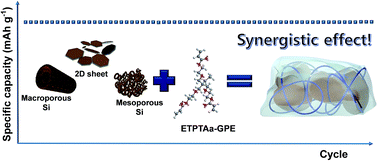
Herein, we synthesize a variety of silicon anode materials featuring well-designed/precisely-controlled nanostructure (including mesoporous, micro-sized macroporous, and two-dimensional (2D) sheet structure) and then combine them with chemically-crosslinked gel polymer electrolytes (GPEs) with an aim to pursue unprecedented synergistic coupling and its versatile applicability for high performance LIB anodes. Meanwhile, the GPE presented herein is in situ synthesized through thermal crosslinking reaction in the presence of silicon materials inside a cell. A predetermined amount of ethoxylated trimethylopropane triacrylate (ETPTA) monomer which was chosen by considering the results of previous studies28,29 is added into liquid electrolyte. The ETPTA monomer/liquid electrolyte mixture is then injected into the cell and subsequently the ETPTA monomer undergoes thermal crosslinking reaction to produce ETPTA polymer networks in the liquid electrolyte, leading to the GPE in close contact with the silicon materials. All of the silicon/GPE systems show significant improvement in cycling performance over control systems containing the silicon/liquid electrolyte. Notably, the silicon/GPE system exhibits a specific capacity of over 2000 mA h g−1 after 100 cycles, and also a half of volume change relative to the control system.

Experimental

Synthesis of nanostructured silicon materials

Mesoporous silicon. 3D mesoporous silicon was synthesized via a metallothermic reduction reaction.21 Firstly, silica foam was prepared according to the previous report.30 4 g of poly(ethylene oxide)-b-poly(propylene oxide)-b-poly(ethylene oxide) (PEO-b-PPO-b-PEO, Pluronic P-123, Sigma-Aldrich) triblock copolymer was dissolved in 150 mL of 1.6 M hydrochloric acid (HCl) solution at 35 °C. Then, 1,3,5-trimethylbenzene (mesitylene, Sigma-Aldrich) as a swelling agent was incorporated into the pre-prepared polymer solution, followed by the addition of 8.5 g of tetraethyl orthosilicate (TEOS, Sigma-Aldrich) as a silica precursor. The resulting solution was vigorously stirred for 24 hours, and maintained at 80 °C for additional 24 hours. Final solid products were filtered and dried at 60 °C in a convection oven. In order to remove residual polymers in the final products, calcination process was conducted at 600 °C for 5 hours in oxygen environment. Subsequently, the resulting silica foam reacted with Mg (Sigma-Aldrich) at 700 °C for 3 hours in argon-filled chamber. After the magnesiothermic reaction, MgO byproducts were completely removed by 1 M HCl solution at 35 °C for 4 hours to obtain pure 3D mesoporous silicon.
Micro-sized macroporous silicon. 1 g of silica with macroporous structure (diatomite, EP Minerals) was uniformly mixed with 0.8 g of Mg powder together in a stainless steel vessel under argon environment. The furnace was heated up to 700 °C at a rate of 5 °C min−1 and kept at this temperature for 3 hours. Then, the final product was immersed in a 1 M HCl solution at 35 °C for 4 hours to remove MgO byproducts.
Silicon sheet. Silicon sheet was prepared by magnesiothermic reaction of a phyllosilicate which is one of the clay minerals. 2 g of illite (alumino-silicate, Samwoo Chemical) was mixed with 1.6 g of Mg powder in argon-substituted vessel. The container was heated in the alumina tube furnace at 700 °C for 3 hours. In order to selectively remove the by-products, the final products were leached in 1 M HCl solution at 35 °C for 4 hours.

Fabrication of gel polymer electrolytes

ETPTA (Mw = 428, Sigma-Aldrich) was mixed with liquid electrolyte (1 M LiPF6 in ethylene carbonate (EC)/diethyl carbonate (DEC), PANAX Starlyte) containing 10 wt% of fluoroethylene carbonate (FEC) as an additive. The weight-based composition ratios of the ETPTA/liquid electrolyte were varied as 2/98, 3/97, 4/96 (w/w), wherein benzoyl peroxide (BPO, 1.0 wt% relative to the ETPTA content) was added as a radical initiator to allow thermal crosslinking reaction. The unit cells (2032-type coin) assembled with the silicon anodes and ETPTA monomer-containing liquid electrolytes were thermally cured at 60 °C for 30 min.

Physicochemical/electrochemical characterization

Surface morphologies of as-prepared silica and silicon were characterized using a scanning electron microscopy (Cold FE-SEM S-4800, Hitachi). For transmission electron microscopy (TEM) measurement (JEM-1400), the silicon particles were dispersed in ethanol and transferred on a Cu grid. The crystalline structure of silicone materials was analyzed by X-ray diffraction (XRD) measurement using Cu Kα radiation from 10 to 90 two theta degree. The thermal-crosslinking reaction of the GPE was investigated using a FT-IR spectrometer (FT-3000, Excalibur) with a spectral resolution of 4 cm−1. The gel content of the GPE was estimated by measuring the weight loss of the samples after being solvent-extracted in dimethyl carbonate at 70 °C for 8 hours and subsequently in acetone at room temperature for 24 hours. The ionic conductivity (σ) of the GPE was obtained using an impedance analyzer (VSP classic, Bio-Logic) over a frequency range of 1 to 103 Hz under a temperature range 30 to 70 °C. The cyclic voltammetry of cells was examined using a potentiostat at a scan rate of 0.1 mV s−1. The silicone anodes were fabricated by traditional slurry coating technique, wherein the composition ratio of the anodes was silicon active material (70 wt%), Super-P as an electroconductive agent (15 wt%) and poly(acrylic acid) (PAA)/sodium carboxymethyl cellulose (CMC) (= 1/1, 15 wt%) as an anode binder. The electrochemical tests of half cells (= silicon anode/GPE/Li metal) were galvanostatically conducted from 0.01 and 1.2 V (versus Li/Li+) at 0.05 and 0.2 C-rates using WBCS 3000 battery system (Wonatech).

Results and discussion

Micrometer-sized silicon anode materials are known to suffer from pulverization due to large volume expansion compared to nanostructured silicon ones.13 In order to better understand advantageous effect of the silicon/GPE coupling and its versatile applicability, we prepared three different kinds of nanostructured silicon materials including mesoporous, micro-sized macroporous, 2D sheet (Scheme 1).
image file: c5ra24256h-s1.tif
Scheme 1 Schematic illustration showing the synergistic coupling of various silicon anode materials (mesoporous, micro-sized macroporous, 2D sheet) and crosslinked ETPTA polymer-mediated GPEs.

Mesoporous silicon

The mesoporous silica was synthesized by introducing silica precursors into self-assembled triblock copolymer template. Notably, the swelling agent (here, mesitylene) plays an important role in controlling pore size.31,32 The use of swelling agent is known to be an effective way to generate numerous nanopores, providing high surface area (686.17 m2 g−1) (ESI, Fig. S1). The dimension of as-prepared silica foam consisted of nanometer-sized primary particles and micron-sized secondary particles (Fig. 1a and b). To make pure silica foam (starting material for magnesiothermic reaction), the triblock copolymer/silica mixtures were heated at 600 °C for 5 hours in O2 environment. Subsequently, the 3D mesoporous silicon was synthesized via magnesiothermic reduction reaction, SiO2 (s) + Mg (g) → Si (s) + MgO (s).33 This chemical reduction is one of the simplest methods to make pure silicon. The MgO by-products were completely removed in HCl solution. The morphological characterization (Fig. 1c and d) of the resultant mesoporous silicon shows that primary silicon particles are aggregated due to the exothermal heat generated during the chemical reduction, compared to pristine silica foam. However, the overall size of secondary particles appears to be similar with that of the as-prepared silica ones. Moreover, the nano-sized silicon particles are interconnected, maintaining interstitial voids formed between the particles (Fig. 1d). The interstitial voids may contribute to accommodating volume change of silicon anode during the repeated lithiation and delithiation process.34 The XRD pattern (Fig. 1e) of an intermediate sample obtained after the magnesiothermic reduction shows the characteristic peaks corresponding to the silicon and MgO byproducts. This result indicates that the subsequent leaching with HCl solution leads to the successful formation of pure silicon.
image file: c5ra24256h-f1.tif
Fig. 1 (a) SEM and (b) TEM images of silica form obtained by heat treatment at 600 °C under air. An inset in the (b) shows the foam-like structure. (c) SEM and (d) TEM images of mesoporous silicon particles synthesized by magnesiothermic reaction of silica form. (e) XRD patterns of mesoporous silicon and MgO by-product after Mg reduction and HCl leaching process, respectively.

Prior to combining the mesoporous silicon with the GPE, the physicochemical properties of the GPE were characterized. Increasing the ETPTA content in the GPEs exerted advantageous influence on the pulverization suppression and interfacial stability with silicon anode materials, however, simultaneously caused the ionic conductivity loss. Taking into such a trade-off behavior of polymer content in the GPEs, the optimum content of polymer matrix was determined. Specifically, the GPE (containing 3 wt% ETPTA) showed the best electrochemical performance, although its ionic conductivity was slightly lower than that of the GPE (with 2 wt% ETPTA). First, the thermal-crosslinking reaction of the GPE was examined by observing the change in the FT-IR peaks assigned to acrylic C[double bond, length as m-dash]C bonds (1610–1625 cm−1) of the ETPTA monomer before/after thermal-curing.35,36 Fig. 2b shows that the characteristic FT-IR peaks of the acrylic C[double bond, length as m-dash]C bonds in the GPE disappeared after the thermal curing. This result verifies the successful thermal-polymerization of ETPTA monomer, which was further confirmed by measuring the gel content of the GPEs. The gel content (i.e. insoluble polymer fraction after solvent (dimethyl carbonate and acetone extraction)) of the GPE was observed to be more than 99%, which demonstrates that the thermal-crosslinking reaction of the ETPTA monomer in the GPEs is almost completed. The mechanical flexibility of the GPE was shown in Fig. 2a and movie (ESI, movie S1). The GPEs featuring these unique physical properties are expected to act as a mechanical cushion which can alleviate the large volume change of silicon anode during the battery operation.


image file: c5ra24256h-f2.tif
Fig. 2 (a) Physical appearance of GPE as a function of the incorporated ETPTA content. (b) FT-IR spectra of acrylic C[double bond, length as m-dash]C double bonds of ETPTA monomer before/after thermal-curing. (c) Temperature-dependent ionic conductivity of GPEs and liquid electrolyte. (d) Cyclic voltammograms of GPEs and liquid electrolyte. (e) Discharge/charge profiles of half cells assembled with mesoporous silicon anode and GPEs at 1st cycle and (f) cycling performance of half cells at discharge/charge current density of 0.2C/0.2C under voltage range of 0.01–1.2 V.

The temperature-dependent ionic conductivity of the GPE is compared with that of the liquid electrolyte containing no ETPTA polymer. Both the GPE and the liquid electrolyte show excellent ionic conductivities over a wide range of temperature (Fig. 2c). Notably, the ionic conductivity of the GPE (incorporating 2 wt% ETPTA) appears to be similar to that of the liquid electrolyte, indicating that the presence of the ETPTA polymer does not exert harmful influence on ion transport in the GPE. Such good ionic conductivity of the GPE can be explained by the unique role of the ETPTA polymer network. Specifically, the ETPTA polymer may have strong interaction with lithium ions due to the presence of nine oxygen atoms of ETPTA molecule, possibly facilitating the dissociation of lithium salts.36,37 In addition, the electrochemical stability window of the GPE was examined by analyzing the cyclic voltammetry (Fig. 2d). No significant decomposition of any components in the GPE takes place in the range of 0.01–1.2 V (vs. Li/Li+), ensuring that the GPE could be electrochemically combined with the silicon anode.

The potential application of the GPE to the mesoporous silicon anode was explored in terms of cell performance. The first galvanostatic voltage profile was shown at discharge/charge current density of 0.05C/0.05C (Fig. 2e). It is of note that the GPE with 2 wt% ETPTA presents the larger initial capacity than the liquid electrolyte. However, the GPE (2 wt% ETPTA) showed a sharp decay in the capacity retention after 66th cycle. In contrast, the GPEs containing the higher amount (3 and 4 wt%) of ETPTA presented better cycling stability. In particular, the improvement in the cycling performance (capacity retention = 92% after 100 cycles) was remarkable at the GPE (3 wt% ETPTA), compared to the cell using liquid electrolyte (capacity retention = 80% after 100 cycles). The relatively inferior capacity retention of the GPE (4 wt% ETPTA) may be ascribed to its lower ionic conductivity (Fig. 2c). This result exhibits that the GPEs, which are characterized with the superior elasticity over the liquid electrolyte (Fig. 2a), can act as an exceptional mechanical cushion to accommodate the volume change of silicon inevitably generated during the lithiation–delithiation reaction, demonstrating the unusual synergistic coupling of mesoporous silicon and GPE (3 wt% ETPTA).

Micro-sized, macroporous silicon

The micrometer-sized 3D macroporous silicon was synthesized via magnesiothermic reaction. Macroporous silica (diatomite) is composed of 90% of silica, 5% of alumina, 1% of iron oxide and trace amounts of different kinds of oxides. According to the Ellingham diagram,38 all of the oxides mentioned above can be converted to reduced species by magnesium vapor. When the molar ratio of silica to magnesium during the magnesiothermic reaction is higher than 1.25, excess Mg reacts with Si product or unreacted silica to generate additional Mg2Si or Mg2SiO4, respectively. The Mg2Si can be easily removed by HCl treatment,39 however, the HCl is not a suitable etchant for Mg2SiO4. If the Mg2SiO4 byproducts, which are electrochemically inert with lithium ions, may not completely removed, the loss of specific capacity of the resultant micro-sized macroporous silicon is difficult to avoid.

Diatomite has a unique shape which is a hollow cylinder (over 15 μm in height) with thick frame (<3 μm), and numerous narrow channels (several hundred nanometer in diameter), as shown in Fig. 3a. After the magnesiothermic reaction and subsequent HCl treatment, the micro-sized macroporous silicon and MgO byproducts were produced without any shape-deformation. The XRD pattern displays that the crystalline phases are exclusively assigned to pure silicon without any other impurities (ESI, Fig. S2). The micro-sized macroporous silicon particles have large numbers of pores which may alleviate the volume change of silicon (inset of Fig. 3b). The voltage profiles at 1st cycle (discharge/charge current density = 0.05C/0.05C, an inset of Fig. 3c) show no significant difference in the capacity between the GPE (3 wt% ETPTA) and liquid electrolyte. However, as the cycle number was increased, the cell containing the GPE provided the substantial improvement in the cycling performance (capacity after 100 cycles = 1191 mA h g−1, Fig. 3c), while the cell with the liquid electrolyte showed the sharp capacity decay (∼800 mA h g−1). This result demonstrates the advantageous effect of the GPE on the long-term electrochemical performance of the micro-sized macroporous silicon anode. Moreover, the cell assembled with the GPE showed the excellent discharge rate capability (e.g., capacity retention at 5.0C (vs. at 0.2C) ∼80%, Fig. 3d).


image file: c5ra24256h-f3.tif
Fig. 3 (a) SEM image of micro-sized macroporous diatomite. An inset shows the macrospores and smooth silica surface. (b) SEM image of micro-sized macroporous silicon synthesized via magnesiothermic reaction of diatomite. An inset is the XRD pattern indicating the formation of pure silicon particles. (c) Cycling performance of micro-sized macroporous silicon anodes combined with GPE (3 wt% ETPTA) or liquid electrolyte. An inset shows the first cycle voltage profiles. (d) Charge rate capability of micro-sized macroporous silicon anode combined with GPE (3 wt% ETPTA).

Silicon sheet

The 2D silicon sheet was synthesized through magnesiothermic reaction of illite, one of the layered clay minerals. The chemical formula of illite is (K, H3O) (Al, Mg, Fe)2 (Si, Al)4O10 [(OH)2, (H2O)]. And, the composition ratio of illite is 47% of silica, 23.3% of alumina, 10% of iron oxide, 6.7% of potassium oxide and so on.40 It consists of thin single unit layers which are piled up to 20 μm in height (Fig. 4a). During the magnesiothermic reaction, the layers of illite are partially exfoliated and subsequently converted to 2D silicon sheet structure with thickness of 10 μm (Fig. 4b). The XRD patterns (Fig. 4c) of the resulting 2D silicon sheets show the successful formation of pure silicon (that was synthesized from illite). The coupling effect of the silicon sheet and GPE on the electrochemical performance was investigated.
image file: c5ra24256h-f4.tif
Fig. 4 (a) SEM images of pristine illite showing sheet-like structure. (b) SEM image of 2D silicon sheets synthesized through magnesiothermic reduction of illite. (c) XRD patterns of illite and 2D silicon sheet. (d) Cycling performance of 2D silicon sheet combined with GPE or liquid electrolyte. An inset shows the discharge/charge voltage profiles at 1st cycle. (e) Cycling performance of carbon-coated 2D silicon sheets combined with two different electrolytes.

The silicon sheet combined with the GPE (3 wt% ETPTA) showed the higher initial capacity (= 1469 mA h g−1) than that with the liquid electrolyte (= 1137 mA h g−1) (inset of Fig. 4d). This beneficial effect of the GPE over the liquid electrolyte could be attributed to physical tightening of the silicon sheets by the crosslinked elastic GPE, thereby allowing larger amount of silicon active materials to participate in the discharge/charge reaction. The 2D silicon sheet combined with the GPE also showed the stable cycling performance (capacity retention ∼ 65% after 150 cycles at 0.2C/0.2C, Fig. 4d). Interestingly, when carbon-coated Si sheets anode (with carbon contents of 10 wt%) was combined with GPE electrolytes, outstanding cycling retention (nearly capacity retention of 100% after 200 cycles at 0.5C rate) was shown compared to electrode combined with liquid electrolyte (Fig. 4e).

Volume change of silicon anodes before/after cycling

To better understand the unique role of the GPE as a mechanical cushion that can alleviate the volume change-induced internal stress of silicon materials during the repeated cycling, the cross-sectional morphologies of silicon anodes before/after cycling test (100 cycles) were analyzed (Fig. 5).
image file: c5ra24256h-f5.tif
Fig. 5 Cross-sectional SEM images showing the volume expansion of various silicon anodes (1st column: as-prepared anodes, 2nd column: anodes containing liquid electrolyte after 100 cycles, 3rd column: anodes containing GPE after 100 cycles). SEM images of (a–c) mesoporous silicon, (d–f) micro-sized macroporous silicon, and (g–i) silicon sheet.

It is of note that the GPE, as compared to the liquid electrolyte, remarkably suppressed the volume expansion of the silicon anodes. Specifically, the volume expansion (after 100 cycles) was found to be 131% vs. 65% (liquid electrolyte vs. GPE) for the mesoporous silicon anodes, 187% vs. 134% for the micro-sized macroporous silicon, and 195% vs. 101% for the silicon sheet. This result demonstrates that the GPE effectively acts as a mechanical cushion to accommodate the volume change (leading to pulverization) of silicon and also preserve the electronic/ionic conduction pathways, eventually providing significant improvement in the long-term cycling performance of the nanostructured silicon materials. Electrochemical performances of various silicon anodes combined with GPE and liquid electrolytes are summarized in the Table S1 (ESI).

Conclusion

We demonstrated the synergistic coupling of nanostructured silicon materials and GPEs for high-performance lithium-ion battery anodes. For all of the silicon anode systems, the mesoporous silicon combined with GPE showed the significant improvement in the cycling performance (capacity retention = 92% after 100 cycles) compared to the silicon anode using liquid electrolyte (capacity retention = 80% after 100 cycles). The chemically-crosslinked ETPTA-mediated elastic GPE acted as a mechanical cushion which can alleviate the volume change of silicon anodes during the repeated cycling and stabilized the interface of silicon materials. More notably, the GPE enabled the remarkable suppression (1.5–2 times less than the liquid electrolytes) in volume expansion of the silicon anodes during the cycling. We anticipate that this coupling strategy based on the nanostructured silicon and the chemically-crosslinked elastic GPE is effective and also versatile, which thereupon can be easily applicable to a vast variety of silicon anode materials suffering from electrochemical pulverization concerns. We are in progress to make full cell combined with the GPE.

Acknowledgements

This work was supported by the IT R&D program of MOTIE/KEIT (10046309) and also supported by the Basic Science Research Program through the National Research Foundation of Korea (NRF) funded by the Ministry of Science, ICT and future Planning (2015R1A2A1A01003474).

Notes and references

  1. M. Armand and J. M. Tarascon, Nature, 2008, 451, 652–657 CrossRef CAS PubMed.
  2. P. Poizot, S. Laruelle, S. Grugeon, L. Dupont and J. M. Tarascon, Nature, 2000, 407, 496–499 CrossRef CAS PubMed.
  3. C. K. Dyer, J. Power Sources, 2002, 106, 31–34 CrossRef CAS.
  4. M. Endo, C. Kim, K. Nishimura, T. Fujino and K. Miyashita, Carbon, 2000, 38, 183–197 CrossRef CAS.
  5. C. Liu, F. Li, L. P. Ma and H. M. Cheng, Adv. Mater., 2010, 22, E28–E62 CrossRef CAS PubMed.
  6. M. M. Thackeray, C. Wolverton and E. D. Isaacs, Energy Environ. Sci., 2012, 5, 7854–7863 CAS.
  7. M. N. Obrovac and L. Christensen, Electrochem. Solid-State Lett., 2004, 7, A93–A96 CrossRef CAS.
  8. S. Hossain, Y.-K. Kim, Y. Saleh and R. Loutfy, J. Power Sources, 2003, 114, 264–276 CrossRef CAS.
  9. C. J. Wen and R. A. Huggins, J. Solid State Chem., 1981, 37, 271–278 CrossRef CAS.
  10. L. Y. Beaulieu, K. W. Eberman, R. L. Turner, L. J. Krause and J. R. Dahn, Electrochem. Solid-State Lett., 2001, 4, A137–A140 CrossRef CAS.
  11. L. Y. Beaulieu, T. D. Hatchard, A. Bonakdarpour, M. D. Fleischauer and J. R. Dahn, J. Electrochem. Soc., 2003, 150, A1457–A1464 CrossRef CAS.
  12. M. Ge, J. Rong, X. Fang and C. Zhou, Nano Lett., 2012, 12, 2318–2323 CrossRef CAS PubMed.
  13. X. H. Liu, L. Zhong, S. Huang, S. X. Mao, T. Zhu and J. Y. Huang, ACS Nano, 2012, 6, 1522–1531 CrossRef CAS PubMed.
  14. C. S. Wang, G. T. Wu, X. B. Zhang, Z. F. Qi and W. Z. Li, J. Electrochem. Soc., 1998, 145, 2751–2758 CrossRef CAS.
  15. P. Gao, J. Fu, J. Yang, R. Lv, J. Wang, Y. Nuli and X. Tang, Phys. Chem. Chem. Phys., 2009, 11, 11101–11105 RSC.
  16. S. Ohara, J. Suzuki, K. Sekine and T. Takamura, J. Power Sources, 2004, 136, 303–306 CrossRef CAS.
  17. C. K. Chan, H. Peng, G. Liu, K. McIlwrath, X. F. Zhang, R. A. Huggins and Y. Cui, Nat. Nanotechnol., 2008, 3, 31–35 CrossRef CAS PubMed.
  18. M. H. Park, M. G. Kim, J. Joo, K. Kim, J. Kim, S. Ahn, Y. Cui and J. Cho, Nano Lett., 2009, 9, 3844–3847 CrossRef CAS PubMed.
  19. K. Fu, O. Yildiz, H. Bhanushali, Y. Wang, K. Stano, L. Xue, X. Zhang and P. D. Bradford, Adv. Mater., 2013, 25, 5109–5114 CrossRef CAS PubMed.
  20. X. Li, M. Gu, S. Hu, R. Kennard, P. Yan, X. Chen, C. Wang, M. J. Sailor, J. G. Zhang and J. Liu, Nat. Commun., 2014, 5, 4105 CAS.
  21. S. Choi, T. Bok, J. Ryu, J.-I. Lee, J. Cho and S. Park, Nano Energy, 2015, 12, 161–168 CrossRef CAS.
  22. K. Xu, Chem. Rev., 2004, 104, 4303–4418 CrossRef CAS PubMed.
  23. J. M. Tarascon, A. S. Gozdz, C. Schmutz, F. Shokoohi and P. C. Warren, Solid State Ionics, 1996, 86–88, 49–54 CrossRef CAS.
  24. T. Sato, T. Maruo, S. Marukane and K. Takagi, J. Power Sources, 2004, 138, 253–261 CrossRef CAS.
  25. B. K. Mandal, A. K. Padhi, Z. Shi, S. Chakraborty and R. Filler, J. Power Sources, 2006, 161, 1341–1345 CrossRef CAS.
  26. K. Murata, S. Izuchi and Y. Yoshihisa, Electrochim. Acta, 2000, 45, 1501–1508 CrossRef CAS.
  27. J.-M. Kim, J.-H. Park, C. K. Lee and S.-Y. Lee, Sci. Rep., 2014, 4, 4602 Search PubMed.
  28. E. H. Kil, H. J. Ha and S. Y. Lee, Macromol. Chem. Phys., 2011, 212, 2217–2223 CrossRef CAS.
  29. H. J. Ha, Y. H. Kwon, J. Y. Kim and S. Y. Lee, Electrochim. Acta, 2011, 57, 40–45 CrossRef CAS.
  30. H. Kim, J. C. Jung, P. Kim, S. H. Yeom, K.-Y. Lee and I. K. Song, J. Mol. Catal. A: Chem., 2006, 259, 150–155 CrossRef CAS.
  31. T. Bok, S. Choi, J. Lee and S. Park, J. Mater. Chem. A, 2014, 2, 14195–14200 CAS.
  32. D. Y. Zhao, J. L. Feng, Q. S. Huo, N. Melosh, G. H. Fredrickson, B. F. Chmelka and G. D. Stucky, Science, 1998, 279, 548–552 CrossRef CAS PubMed.
  33. Z. Bao, M. R. Weatherspoon, S. Shian, Y. Cai, P. D. Graham, S. M. Allan, G. Ahmad, M. B. Dickerson, B. C. Church, Z. Kang, H. W. Abernathy 3rd, C. J. Summers, M. Liu and K. H. Sandhage, Nature, 2007, 446, 172–175 CrossRef CAS PubMed.
  34. N. Liu, Z. Lu, J. Zhao, M. T. McDowell, H. W. Lee, W. Zhao and Y. Cui, Nat. Nanotechnol., 2014, 9, 187–192 CrossRef CAS PubMed.
  35. H. J. Ha, E. H. Kil, Y. H. Kwon, J. Y. Kim, C. K. Lee and S. Y. Lee, Energy Environ. Sci., 2012, 5, 6491–6499 CAS.
  36. S. H. Kim, K. H. Choi, S. J. Cho, E. H. Kil and S. Y. Lee, J. Mater. Chem. A, 2013, 1, 4949–4955 CAS.
  37. K. H. Choi, S. J. Cho, S. H. Kim, Y. H. Kwon, J. Y. Kim and S. Y. Lee, Adv. Funct. Mater., 2014, 24, 44–52 CrossRef CAS.
  38. H. J. T. Ellingham, J. Soc. Chem. Ind., 1944, 63, 125–133 CrossRef CAS.
  39. W. Chen, Z. Fan, A. Dhanabalan, C. Chen and C. Wang, J. Electrochem. Soc., 2011, 158, A1055–A1059 CrossRef CAS.
  40. T. E. Bell, Clays Clay Miner., 1986, 34, 146–154 CAS.

Footnotes

Electronic supplementary information (ESI) available: Nitrogen absorption–desorption curve of mesoporous silicon and mechanical property of GPEs. See DOI: 10.1039/c5ra24256h
These authors equally contributed to this work.

This journal is © The Royal Society of Chemistry 2016
Click here to see how this site uses Cookies. View our privacy policy here.