Solvate ionic liquid electrolyte with 1,1,2,2-tetrafluoroethyl 2,2,2-trifluoroethyl ether as a support solvent for advanced lithium–sulfur batteries

Hai Lu*a, Yan Yuanb, Zhenzhong Houa, Yanqing Laic, Kai Zhangc and Yexiang Liuc
aSchool of Materials Science and Engineering, Xi'an University of Science and Technology, Xi'an 710054, China. E-mail: lhxust@126.com
bSchool of Metallurgical Engineering, Xi'an University of Architecture and Technology, Xi'an 710055, China
cSchool of Metallurgy and Environment, Central South University, Changsha 410083, China

Received 16th November 2015 , Accepted 27th January 2016

First published on 29th January 2016


Abstract

1,1,2,2-Tetrafluoroethyl 2,2,2-trifluoroethyl ether (TFTFE) was added to a solvate ionic liquid (SIL) based on glyme-lithium salt as a support solvent. The fluorinated ether improves cycle and rate capability of Li–S cells. The key role that TFTFE played in the cell system with SIL is an ionic conduction-enhancing ingredient, especially for high-rate cycle environment.

The issues of energy shortage and environment pollution propel the development of electric vehicles. To cater to the strict requests for vehicle-loaded power, all kinds of advanced energy storage devices have been studied extensively.1 Among these, lithium​–sulfur (Li–S) battery has attracted worldwide attentions by virtue of its theoretical energy density of up to 2600 W h kg−1,2 which is 10 times higher than that of conventional lithium-ion batteries (LIBs). Besides, sulfur has the advantages of non-toxicity and abundance in nature, whereas LIB cathode materials typically contain rare metals.

However, a critical problem originated from redox conversion process of the Li–S batteries is the dissolution of reaction intermediate polysulfides (PS) in the electrolyte.3 The dissolved PS tends to generate repeating shuttle between the cathode and anode,4 resulting in low coulombic efficiency and fast self-discharge. Furthermore, the PS can be electrochemically and chemically reduced on Li metal, causing such problems as (a) consuming active species, (b) corroding Li anode, and (c) polarizing Li anode once insoluble products are formed and deposited on the Li surface.5 Hence the restrictions towards PS are very necessary for boosting cell performance. Optimizing electrolyte composition is often attempted for this purpose, e.g., altering solvent type, controlling electrolyte amount or introducing functional additives, etc.6–8 However these approaches are still hard to avoid the dissolution and shuttle of PS completely.

Recently, solvate ionic liquid (SIL)9 begins to enter the research scope of the Li–S batteries owing to its distinctive structure and properties. The typical case of SIL is the equimolar mixtures of tetraglyme (G4) and certain Li salts (LiX).10 The formation of complex Li(G4)1X will weaken the donor ability of G4 solvent because all of the lone pairs of the ether oxygen atoms are donated to the Li+ (as we know, the coordination number of Li+ is 4–5).11 Thus the PS is poorly solvated in the SIL and quite low solubility of PS can be obtained easily in SIL,12 which reflects the superiority of SIL applying in the Li–S batteries compared to other electrolyte systems. Research results show that SIL electrolyte allows the cell to have a stable charge–discharge cycles and a coulombic efficiency of greater than 99%.12 However, the cell capacity is still a bit low over the whole cycling period. Besides, the high viscosity of the SIL gives rise to certain polarization, which is harmful to the potential plateau and rate capability of the cell. Interestingly, It is reported that organo-fluorine compound is capable of enhancing the cell energy and power density once it was added into the SIL,11 which utilizes the complementary and synergistic actions between SIL and fluorinated ether.

In the study, we aims to select another novel fluorinated ether derivative named 1,1,2,2-tetrafluoroethyl 2,2,2-trifluoroethyl ether (TFTFE) as the support solvent of SIL. Significant improvements of TFTFE-contained electrolyte on electrochemical performances of the Li–S cell are demonstrated here, and the key role of TFTFE in the cell system with SIL is discussed. Several electrolytes using in this experiment were prepared as follows: lithium bis(trifluoromethane sulfonel)imide (LiTFSI, Aldrich) and G4 (Adamas) were mixed at equimolar ratio and magnetically stirred at 50 °C overnight in a argon-filled glove box, forming Li(G4)1TFSI (LiTFSI[thin space (1/6-em)]:[thin space (1/6-em)]G4 = 1[thin space (1/6-em)]:[thin space (1/6-em)]1, molar ratio). Then the stoichiometric TFTFE (Adamas) was further added into above Li(G4)1TFSI to obtain a series of solution mixtures Li(G4)1TFSI–xTF (LiTFSI[thin space (1/6-em)]:[thin space (1/6-em)]G4[thin space (1/6-em)]:[thin space (1/6-em)]TFTFE = 1[thin space (1/6-em)]:[thin space (1/6-em)]1[thin space (1/6-em)]:[thin space (1/6-em)]x, molar ratio, x = 1–6).

In general, the required properties of a support solvent for SIL electrolyte Li(G4)1TFSI in Li–S cells include:11

(a) Chemical stability against PS;

(b) Reductive stability against Li metal;

(c) Miscibility with Li(G4)1TFSI;

(d) Better mobility than Li(G4)1TFSI;

(e) Low donor ability for limiting PS dissolution;

(f) Weak interaction with solvate structure of Li(G4)1TFSI.

We have exhibited for the first time that TFTFE is suitable for application in Li–S cells as a co-solvent.13 Reversible capacity and coulombic efficiency of the cell can be increased distinctly when TFTFE was mixed with conventional ethers. So it is undoubted that TFTFE owns favourable chemical stability against PS and reductive stability against Li metal. Meanwhile, the fluorinated ether is miscible with conventional ethers such as G4, thus also can be blended with Li(G4)1TFSI. As for the mobility, the conductivity meter (Mettler Toledo, SG3) and viscometer (Brookfield, DV2T-LV) were used for measuring the conductivity and viscosity of the electrolyte, respectively. It is found that Li(G4)1TFSI–4TF has higher ion conductivity and lower viscosity (6.81 ms cm−1 and 4.56 mPa s as measured) than Li(G4)1TFSI (1.6 ms cm−1 and 81 mPa s as reported10), which means TFTFE favours the improvement of transport property on the basis of SIL.

The fluorinated ether has very low donor ability because it is always too fluorinated to participate in Li+ solvation.14 In order to realize the solubility of PS in various electrolytes, S and Li2S with a molar ratio of 7[thin space (1/6-em)]:[thin space (1/6-em)]1 were mixed and added in each electrolyte (the theoretical content of Li2S8 was controlled to be 0.25 mol L−1). As the solubility of PS in the electrolyte has been characterized extensively by observing the colour of the electrolyte containing PS,15,16 the pictures of various solutions after different standing time are recorded and compared in Fig. 1a. Generally, the normal electrolyte without any PS presents colourless and transparent. However, the colour of Li(G4)1TFSI once adding Li2S8 becomes yellow and deepens gradually with time. In principle, the lone pairs of the ether oxygen are all donated to Li+ in Li(G4)1TFSI, and the stable Li(G4)1+ complex ion can be formed due to strong ion–dipole interaction between Li+ and G4.17 Hence PS dissolves hardly in the SIL. But the above colour change suggests that the solubility of PS still exists to some extent for Li(G4)1TFSI. When using TFTFE as support solvent, the Li(G4)1TFSI–xTF solution seems lighter than Li(G4)1TFSI at the same standing steps. Especially the colour of Li(G4)1TFSI–4TF is close to colourless and nearly unchanged after standing for 6 days. It suggests that the dissolution of PS is further decreased in the TFTFE-contained electrolyte. Moreover, the dissolution quantity of polysulfide decreases gradually as TFTFE content in the electrolyte raises (see ESI, Fig. S1 and S2). Therefore, more TFTFE contributes to weaker dissociation of PS compared to Li(G4)1TFSI.


image file: c5ra24182k-f1.tif
Fig. 1 (a) Solubility experiments of polysulfides in various electrolytes; (b) LSV measurements of various electrolytes at a scanning rate of 5 mV s−1.

The low donor ability implies that TFTFE is hard to overwhelm G4 in Li+ solvation as well. This speculation can be verified from linear sweep voltammetry (LSV) measurements of stainless steel/Li cells loaded various electrolytes (scanning rate: 0.5 mV s−1). As shown in Fig. 1b, the anodic limits of equimolar complex Li(G4)1TFSI is near 5 V vs. Li/Li+, exhibiting high oxidative stability of the SILs. After adding TFTFE, the LSV curves of Li(G4)1TFSI–xTF move towards low-potential direction slightly. The free ether (G4, in this case), which are not involved in the complex with Li+, will be decomposed irreversibly at higher than 4 V vs. Li/Li+.18 The oxidative limits of Li(G4)1TFSI–xTF is very close to that of Li(G4)1TFSI, revealing that the majority of complex cations Li(G4)1+ still exist steadily and free G4 is scarce in the TFTFE-contained system. In other words, the distinctive solvate structure of SIL is reserved although TFTFE was introduced into the electrolyte.

It can be seen from the above results that TFTFE meets all the demands for support solvent of SIL and can cooperate ideally with it. Next the electrochemical performances of Li–S cells with various electrolytes were investigated. Sulfur–carbon composite (S–C, 79.1% sulfur, see ESI, Fig. S3) was prepared according to the method described previously.19 Sulfur cathode consisted of 80 wt% S–C composite, 10 wt% carbon black (Super P, Timcal) and 10 wt% poly(vinylidene fluoride) (PVDF, 6020 Solef). The sulfur loading on each cathode was ∼1.2 mg cm−1. Coin cells were assembled in the glove box by using above sulfur cathode, Li foil as anode and Advantec GA55 as separator. The electrolyte amount in each cell was controlled to be ∼18 mL g−1 (the ratio of electrolyte volume to sulfur content in the cathode).

Firstly, the cyclic voltammetry (CV) for the cell with Li(G4)1TFSI and Li(G4)1TFSI–4TF are presented in Fig. 2a and b, respectively. The sweep rate is 0.1 mV s−1. All of the cells show two reduction peaks and two very close oxidation peaks (similar to those cases using G4 in electrolyte20). The reduction peaks in cathodic scan stand for the reduction of elemental sulfur to soluble PS and then to the insoluble Li2S2/Li2S, respectively. And the oxidation peaks in anodic scan represent the formation of PS and the final oxidized active sulfur (Li2S8 or S), respectively.20–22 The CV patterns in the first fourth cycles almost overlap each other, indicating steady cycle ability of the cells with the two electrolytes. It should be noted that the second reduction peak is located at higher value and the voltage gap between oxidation and reduction peaks is smaller for the cell with Li(G4)1TFSI–4TF compared to that for Li(G4)1TFSI. TFTFE enhances ion conduction of the electrolyte, thus decreases the over-potential and improves reversibility of the cell.


image file: c5ra24182k-f2.tif
Fig. 2 Cyclic voltammogram of the Li–S cell with (a) Li(G4)1TFSI and (b) Li(G4)1TFSI–4TF at a sweep rate of 0.1 mV s−1; (c) initial potential profiles and (d) cycle performances of the cells with various electrolytes at 0.1C.

Fig. 2c is the initial potential profiles of the Li–S cells with various electrolytes at 0.1C between 1.5 V and 3 V. Two plateaus can be clearly observed from the discharge curves, corresponding to two-step reaction of sulfur with metallic Li. The low-potential plateau for Li(G4)1TFSI–xTF reaches ∼2.1 V, higher than that for Li(G4)1TFSI (∼2.0 V). Meanwhile, the gaps between discharge plateau and charge plateau of the cells containing TFTFE is smaller than that using pure SIL. These phenomena are well consistent with above CV results. In addition, initial discharge capacity of the cell increases when the amount of TFTFE in the electrolyte increases. Since adding the fluorinated ether can further limit the dissolution of PS at the discharge stage, more active sulfur can be recovered reversibly during the subsequent charging process.23 So TFTFE is beneficial to the utilization of active material.

The cycle performances of Li–S cells with various electrolytes are shown in Fig. 2d (more information seen Fig. S4 in ESI). For the electrolyte containing fluorinated ether, the cell capacity keeps quite stable and the coulombic efficiency approaches 100% after the first cycle, similar to the variation characteristic of the cell with SIL. Obviously, TFTFE existing in SIL indeed won't affect inhibition ability of the electrolyte to PS dissolution and shuttle. The relatively low TFTFE content contributes to more reversible capacity during the whole cycle period, for instance: a reserved capacity of ∼580 mA h g−1 is obtained after 30 cycles for Li(G4)1TFSI–2TF. But it needs to be recognized that the improvement of TFTFE to the cell performance is a bit insufficient at the current condition. When continuing to increase TFTFE ratio in the SIL, the cycle capability of the cell declines instead, even though the first discharge capacity increases and the coulombic efficiency still keeps in high level. The previous LSV measurement shows that the deviation trend enlarges slightly with an increase in TFTFE ratio. So adding more TFTFE may expand negative effect to SIL structure, which in turn weaken the electrochemical stability of the cell.

The electrochemical performances of the cell at high rate are further investigated. The specific capacities at different discharge rates for various electrolytes are presented in Fig. 3a (the charge rate is uniformly 0.1C). The cell capacities using TFTFE-contained electrolytes are always superior to that using pure SIL at each rate. Among them, the cell with Li(G4)1TFSI–4TF exhibits the best rate capability: stable specific capacities of 480 mA h g−1 and 500 mA h g−1 can be delivered when the current is elevated to 0.5C and turned back to 0.3C after 0.5C cycles, respectively. Since adding TFTFE increases ion conductivity of the electrolyte, the polarization will decline when cell is operated at high-rate conditions. Hence it should be no surprise that the rate performance of the cell is improved remarkably if using TFTFE as support solvent.


image file: c5ra24182k-f3.tif
Fig. 3 (a) Rate performances of the cells with various electrolytes from 0.1C to 0.5C; (b) cycle performances of the cells with various electrolytes at 0.3C; charge–discharge curves of the cell with (c) Li(G4)1TFSI–4TF and (d) Li(G4)1TFSI at 0.3C.

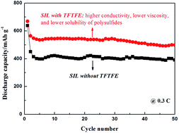
The cycle capabilities of the cells with various electrolytes at charge/discharge rate of 0.3C are compared in Fig. 3b. The excellent cycle stability appears in the cell with Li(G4)1TFSI–4TF. The capacity retention after 50 cycles is up to 88.3% based on the second discharge. Moreover, Li(G4)1TFSI–4TF allows the cell to release more capacities than Li(G4)1TFSI during cycling. The difference of cell performance between two kinds of electrolytes at high rate is more noticeable than that at low rate. Besides, the discharge plateau for Li(G4)1TFSI–4TF also overtops Li(G4)1TFSI at initial cycle (see ESI, Fig. S5), demonstrating less over-potentials in the former. The plateau potential ascends step by step and then maintains stable during subsequent cycles in the case of Li(G4)1TFSI–4TF (Fig. 3c), which reveals the achievement of a stable electrochemical environment needs a procedure, like other electrolytes using abundant fluorinated ether.20 While the discharge plateau for Li(G4)1TFSI is stable all the time (Fig. 3d). Therefore, the polarization gap between two electrolytes is further enlarged at latter cycles.

To better understand the function of TFTFE in the cell system, the electrochemical impedance spectroscopy (EIS) of the Li–S cells with various electrolytes was examined. The frequency range of the measurement was 105–0.1 Hz, with the perturbation amplitude of 5 mV. The impedance plots before cycle are composed of a semicircle in medium-to-high frequency and an inclined line in the low frequency (Fig. 4a). The former is attributed to the interface charge-transfer resistance (Rct), and the latter corresponds to Warburg impedance (Wo, associated with Li+ diffusion in the active material). The high-frequency intercept on the real axis represents the ohmic resistance (Ro), including the electrolyte and electrode resistances.24 After 50 cycles, the impedance responses are divided into two obvious semicircles (Fig. 4b). The additional semicircle in the high frequency is related to solid-electrolyte interface (SEI) film formed during the charge–discharge process (Rs).25,26 The fitted resistance data according to the corresponding equivalent circuit are shown in Table 1.


image file: c5ra24182k-f4.tif
Fig. 4 EIS plots of Li–S cells with various electrolytes (a) before cycle and (b) after cycles.
Table 1 Fitted resistances data from the equivalent circuit
Electrolyte Stage R0 (Ω) Rs (Ω) Rct (Ω)
Li(G4)1TFSI Before cycle 11.36 80.64
After cycles 12.84 25.23 8.78
Li(G4)1TFSI–4TF Before cycle 2.57 70.71
After cycles 4.25 30.66 6.41


The Ro for the cell with fluorinated ether is obviously smaller than the one without it, which is another convincing evidence of TFTFE on promoting ion transport of the electrolyte. The decline in Rct for Li(G4)1TFSI–4TF compared to Li(G4)1TFSI suggests that the electrolyte containing TFTFE is capable of wetting the electrode sufficiently and improving the electrochemical reaction within the cell.14,25 The increase in Rs is probably associated with film building of TFTFE on Li anode, which can block the access of PS to metallic Li and side-reactions between them.13 However, whether modified surface film or further reduced PS dissolution should be minor contributing factor for improving cell performance in the high concentration electrolytes, considering that the dissolution and shuttle of PS have already been negligible at this moment. Combining the resistance data with previous electrochemical tests, it can be concluded that the more important role of TFTFE played in the cell system using SIL should be an ionic conduction-enhancing ingredient, especially for high-rate cycle environment.

In summary, we have investigated the effects of adding fluorinated ether on the basic properties of SIL electrolyte and electrochemical performances of Li–S cells. TFTFE meets the demands for support solvent of SIL, including favourable mobility, low dissolution ability of PS and weak interaction with solvate structure, thus is suitable for cooperating with SIL. The cell using the fluorinated ether owns higher reversible capacity than the one without it, accompanied by coulombic efficiency near 100% and quite stable cycle capability. Especially, the low polarization and excellent performance are exhibited in the high-rate measurement of the cell with TFTFE. The capacity retention after 50 cycles is up to 88.3% based on the second discharge at 0.3C charge–discharge test for Li(G4)1TFSI–4TF. Here, the enhanced ion conduction by TFTFE is mainly contributive for the improvement of the cell performance.

Acknowledgements

The authors thank the financial support of the National Natural Science Foundation of China (No. 21204072). We also thank the support of viscosity measurement provided by the Analytical & Testing Center, Material & Industrial Technology Research Institute, Beijing.

Notes and references

  1. L. Li, Z. Wu, S. Yuan and X.-B. Zhang, Energy Environ. Sci., 2014, 7, 2101–2122 CAS.
  2. M. K. Song, E. J. Cairns and Y. Zhang, Nanoscale, 2013, 5, 2186–2204 RSC.
  3. M. Barghamadi, A. S. Best, A. I. Bhatt, A. F. Hollenkamp, M. Musameh, R. J. Rees and T. Rüther, Energy Environ. Sci., 2014, 7, 3902–3920 CAS.
  4. Y. V. Mikhaylik and J. R. Akridge, J. Electrochem. Soc., 2004, 151, A1969–A1976 CrossRef CAS.
  5. S. S. Zhang, J. Power Sources, 2013, 231, 153–162 CrossRef CAS.
  6. S. Yoon, Y.-H. Lee, K.-H. Shin, S. B. Cho and W. J. Chung, Electrochim. Acta, 2014, 145, 170–176 CrossRef CAS.
  7. X.-B. Cheng, J.-Q. Huang, H.-J. Peng, J.-Q. Nie, X.-Y. Liu, Q. Zhang and F. Wei, J. Power Sources, 2014, 253, 263–268 CrossRef CAS.
  8. F. Wu, J. Qian, R. Chen, J. Lu, L. Li, H. Wu, J. Chen, T. Zhao, Y. Ye and K. Amine, ACS Appl. Mater. Interfaces, 2014, 6, 15542–15549 CAS.
  9. T. Mandai, K. Yoshida, K. Ueno, K. Dokko and M. Watanabe, Phys. Chem. Chem. Phys., 2014, 16, 8761–8772 RSC.
  10. K. Ueno, K. Yoshida, M. Tsuchiya, N. Tachikawa, K. Dokko and M. Watanabe, J. Phys. Chem. B, 2012, 116, 11323–11331 CrossRef CAS PubMed.
  11. K. Dokko, N. Tachikawa, K. Yamauchi, M. Tsuchiya, A. Yamazaki, E. Takashima, J. W. Park, K. Ueno, S. Seki, N. Serizawa and M. Watanabe, J. Electrochem. Soc., 2013, 160, A1304–A1310 CrossRef CAS.
  12. C. Zhang, A. Yamazaki, J. Murai, J.-W. Park, T. Mandai, K. Ueno, K. Dokko and M. Watanabe, J. Phys. Chem. C, 2014, 118, 17362–17373 CAS.
  13. H. Lu, Y. Yuan, K. Zhang, F. Qin, Y. Lai and Y. Liu, J. Electrochem. Soc., 2015, 162, A1460–A1465 CrossRef CAS.
  14. M. Cuisinier, P. E. Cabelguen, B. D. Adams, A. Garsuch, M. Balasubramanian and L. F. Nazar, Energy Environ. Sci., 2014, 7, 2697–2705 CAS.
  15. L. Suo, Y. Hu, H. Li, M. Armand and L. Chen, Nat. Commun., 2013, 4, 1481 CrossRef PubMed.
  16. N. Azimi, Z. Xue, I. Bloom, M. L. Gordin, D. Wang, T. Daniel, C. Takoudis and Z. Zhang, ACS Appl. Mater. Interfaces, 2015, 7, 9169–9177 CAS.
  17. C. Zhang, K. Ueno, A. Yamazaki, K. Yoshida, H. Moon, T. Mandai, Y. Umebayashi, K. Dokko and M. Watanabe, J. Phys. Chem. B, 2014, 118, 5144–5153 CrossRef CAS PubMed.
  18. K. Yoshida, M. Nakamura, Y. Kazue, N. Tachikawa, S. Tsuzuki, S. Seki, K. Dokko and M. Watanabe, J. Am. Chem. Soc., 2011, 133, 13121–13129 CrossRef CAS PubMed.
  19. J. Li, F. Qin, L. Zhang, K. Zhang, Q. Li, Y. Lai, Z. Zhang and J. Fang, J. Mater. Chem. A, 2014, 2, 13916–13922 CAS.
  20. H. Lu, K. Zhang, Y. Yuan, F. Qin, Z. Zhang, Y. Lai and Y. Liu, Electrochim. Acta, 2015, 161, 55–62 CrossRef CAS.
  21. Y.-S. Su and A. Manthiram, Electrochim. Acta, 2012, 77, 272–278 CrossRef CAS.
  22. Z. Dong, J. Zhang, X. Zhao, J. Tu, Q. Su and G. Du, RSC Adv., 2013, 3, 24914–24917 RSC.
  23. Y. Diao, K. Xie, X. Hong and S. Xiong, Acta Chim. Sin., 2013, 71, 508–518 CrossRef CAS.
  24. F. Qin, K. Zhang, J. Fang, Y. Lai, Q. Li, Z. Zhang and J. Li, New J. Chem., 2014, 38, 4549–4554 RSC.
  25. Q. Li, Z. Zhang, K. Zhang, J. Fang, Y. Lai and J. Li, J. Power Sources, 2014, 256, 137–144 CrossRef CAS.
  26. X. Cui, Z. Shan, L. Cui and J. Tian, Electrochim. Acta, 2013, 105, 23–30 CrossRef CAS.

Footnote

Electronic supplementary information (ESI) available. See DOI: 10.1039/c5ra24182k

This journal is © The Royal Society of Chemistry 2016
Click here to see how this site uses Cookies. View our privacy policy here.