
Comparison of hydrogen, halogen, and tetrel bonds in the complexes of HArF with YH3X (X = halogen, Y = C and Si)†
Mingxiu Liua,
Qingzhong Li*a,
Wenzuo Lia,
Jianbo Chenga and
Sean A. C. McDowell*b
aThe Laboratory of Theoretical and Computational Chemistry, School of Chemistry and Chemical Engineering, Yantai University, Yantai 264005, P. R. China. E-mail: liqingzhong1990@sina.com; Fax: +86 535 6902063; Tel: +86 535 6902063
bDepartment of Biological and Chemical Sciences, The University of the West Indies, Cave Hill Campus, Barbados. E-mail: sacm@mail.com
First published on 10th February 2016
Abstract
Ab initio MP2/aug-cc-pVTZ calculations were performed in order to find equilibrium structures with Y⋯F tetrel bonds, X⋯H hydrogen bonds or X⋯F halogen bonds on the potential energy surfaces of the complexes formed between HArF and YH3X (X = halogen, Y = C and Si). For the CH3X complexes, the hydrogen-bonded complex is the most stable, while the tetrel-bonded complex is the most stable of the SiH3X complexes. The H–Ar stretch vibration exhibits a red shift for the hydrogen bond but a blue shift for the tetrel and halogen bonds. The hydrogen bonds in the CH3X and SiH3X complexes, as well as the tetrel bonds in the SiH3X complexes, are governed by a combination of electrostatic and polarization energies, exhibiting partially covalent character with negative energy densities and a substantial amount of charge transfer.
1. Introduction
Molecules containing noble gas atoms have attracted much attention because they exhibit distinctive structures and specialised properties. For instance, the H–Ar stretch vibration of HArF often displays a blue shift when this molecule participates in hydrogen bonding.1–10 This is in sharp contrast to conventional hydrogen bonds for which a red shift is commonly observed. Moreover, this vibration shows a rather large blue shift when the F atom of HArF forms a halogen bond with dihalogen molecules.11 Experimenters have tried to synthesize these types of noble gas molecules using various preparative techniques, most commonly low-temperature matrix isolation methods.12–14 Most noble gas molecules contain a fluorine atom, such as HArF,12 XePtF6,15 and KrF2.16 On the other hand, there is also much richness and diversity in fluorine-free noble gas chemistry.17–19 Most of these noble gas molecules are metastable in the gas phase and have potentially high reactivity. Consequently, it is a challenge to stabilize these noble gas molecules in solution.It has been demonstrated previously that the noble gas molecules can form stable intermolecular complexes with ordinary molecules.1–11,20–27 A hydrogen bond is usually involved in the complexes of HNgY, where Ng denotes a noble gas atom and Y is an electronegative fragment. The molecule HNgY is characterized by both a covalent H–Ng bond and an ionic Ng–Y bond. Interestingly, a blue shift occurs for the H–Ng stretch vibration when it forms a hydrogen bond with small molecules such as H2, N2, CO, and CO2.1–10 However, the H–Ng stretch vibration shows a red shift when it participates in a hydrogen bond with P2 (ref. 23 and 24) and metal hydrides.25–27 The HArF molecule can form two stable complexes with dihalogen molecules through a hydrogen bond and a halogen bond, with the halogen-bonded complex being more stable than the hydrogen-bonded counterpart.11 Moreover, a large blue shift of the H–Ar stretching frequency was found in both complexes, but it amounts to about 200–398 cm−1 in the halogen-bonded complex.11 It was shown that the H–Ng stretching frequency has a dependence on the nature of the noble gas atom.28,29 For example, the H–Ng stretching frequency has a large blue shift in the π hydrogen-bonded complex C6H6–HArF, no shift in the corresponding complex C6H6–HKrF, but a small red shift in the corresponding complex C6H6–HXeF.28 In addition, we also studied the complexes of HArF and XH2P (X = F, Cl, and Br) and found three stable complexes.30 The pnicogen bond formed between the σ-hole (a region with positive electrostatic potentials) on the P atom of XH2P and the F atom of HArF is stronger than the hydrogen bond formed between the H atom of HArF and the lone pair on the P atom, as well as the halogen bond formed between the F atom of HArF and the halogen atom X of XH2P.30 Recently, Bauzá and Frontera31 proposed the term “aerogen bonding” to describe the σ-hole interaction between Lewis bases and the noble gas atom and suggested that this interaction may act as a new supramolecular force in crystal materials.
In this paper, we studied the complexes formed between HArF and YH3X (X = halogen, Y = C and Si) in order to present a detailed investigation of their stabilities, electronic structures, and vibrational frequencies using quantum chemical calculations. Each molecular pair can be combined via three different binding modes, including a hydrogen bond (HB), a halogen bond (XB), and a tetrel bond (TB). Tetrel bonding is a σ-hole interaction between a region of positive electrostatic potential on the outer surface of the tetrel atom and a neighbouring negative site. This interaction has been suggested to be important in crystal materials,32–34 chemical reactions,35 and biological systems.36 We first explain the formation of the three interactions based on molecular electrostatic potentials, then we compare the stability of the three different complexes via their interaction energies and investigate the stability of the complexes with an energy decomposition method. The vibrational frequency shift of the H–Ar stretch vibration was analyzed by considering orbital interactions and occupancies.
2. Theoretical methods
All calculations were carried out with the Gaussian 09 program.37 The geometries of the complexes and the respective monomers were optimized at the MP2 level with the aug-cc-pVTZ basis set for all atoms except the iodine atom. The aug-cc-pVTZ-PP basis set was adopted for the iodine atom to account for relativistic effects. Harmonic frequency calculations were then performed at the same level to confirm that the obtained structures correspond to energy minima on the potential energy surfaces. The interaction energy was calculated as the difference between the energy of the complex and the energy sum of the respective monomers. The interaction energy was corrected for the basis set superposition error (BSSE) with the counterpoise method of Boys and Bernardi.38The molecular electrostatic potential (MEP) of YH3X (X = halogen, Y = C and Si) on the 0.001 electrons per bohr3 contour of the electronic density were calculated at the MP2/aug-cc-pVTZ level with the wavefunction analysis-surface analysis suite (WFA-SAS) program.39 The topological analysis for all complexes was performed by using Bader's theory of atoms in molecules (AIM) with the help of AIM2000 software.40 Natural bond orbital (NBO) analysis41 was carried out at the HF/aug-cc-pVTZ level via the procedures contained in Gaussian 09 to analyze orbital interactions, occupancy, and charge transfer. The GAMESS program42 was used to perform an energy decomposition analysis for the interaction energy using the LMOEDA method43 at the MP2/aug-cc-pVTZ level.
3. Results and discussion
3.1 MEPs of XH3Y
To gain an understanding of the interaction modes between YH3X and HArF, we plotted the map of molecular electrostatic potentials (MEPs) of SiH3Br in Fig. 1. A σ-hole is evident on the outer side of the Br atom along the Si–Br bond and this σ-hole is surrounded by the negative MEPs, corresponding to the lone pairs on the Br atom. As a result, it is reasonable to consider the σ-hole on the Br atom as the Lewis acid site for formation of a halogen bond with the F atom (Lewis base) of HArF and for the lone pair on the Br atom to act as the Lewis base for formation of a hydrogen bond with the proton of HArF. Simultaneously, four σ-holes are also observed at the tetrahedral face centers of SiH3Br, in which the σ-hole along the Br–Si bond has a larger positive MEP (red region) than the other three σ-holes (yellow region) along the H–Si bond. Henceforth, we shall only focus on the larger σ-hole on the Si atom, which can form a tetrel bond with the F atom of HArF. | ||
| Fig. 1 MEP maps of SiH3Br. Color ranges are: red, greater than 105; yellow, between 105 and 52; green, between 52 and 0; blue, less than 0. All are in kJ mol−1. | ||
The values of the related electrostatic potentials of YH3X (X = halogen, Y = C and Si) are given in Table 1. No σ-hole is present on the F atom of CH3F and SiH3F, due to the fact that F has a greater electronegativity and lower polarizability than the other X (and Y) atoms. The most positive MEP on the halogen atom, Vmax(X), becomes larger with increasing halogen atomic mass. When the C atom in CH3X is replaced by Si, the value of Vmax(X) is reduced and it even becomes negative on the Cl atom of SiH3Cl, owing to the lower electronegativity of Si. On the other hand, the most negative MEP on the halogen atom, Vmin(X), becomes less negative with an increase of halogen atomic number. The X atom in CH3X shows a larger Vmin(X) than that in SiH3X although the C atom has a greater electronegativity than the Si atom. The most positive MEP on the Y atom, Vmax(Y), becomes larger for the lighter X atom and the heavier Y atom. Importantly, Vmax(Y) is much larger than Vmax(X) except in CH3I, indicating that the tetrel atom is a stronger Lewis acid than the halogen atom.
| Vmax(X) | Vmax(Y) | Vmin(X) | |
|---|---|---|---|
| a The MEP at the outer end of C–F bond in CH3F is −92.34 kJ mol−1. | |||
| CH3F | — | 87.90 | −95.71 |
| CH3Cl | 2.07 | 73.46 | −61.28 |
| CH3Br | 27.04 | 66.88 | −55.39 |
| CH3I | 56.82 | 54.04 | −46.72 |
| SiH3F | — | 162.84 | −86.59 |
| SiH3Cl | −5.94 | 150.62 | −39.27 |
| SiH3Br | 14.95 | 145.86 | −35.06 |
| SiH3I | 40.68 | 135.01 | −29.41 |
3.2 Structures and energetics
Fig. 2 shows the structures of complexes between YH3X and HArF. The respective geometrical parameters are collected in Table 2. For the tetrel-bonded complexes of CH3X (1–4), the molecule HArF is in line with the C–X bond, whereas for the tetrel-bonded complexes of SiH3X (12–15), the molecule HArF is not in line with the Si–X bond, making an angle of about 103°. For the hydrogen-bonded complexes (5–8 and 17–19), the molecule HArF deviates from the line of the Y–X bond and this deviation is reduced with the increase of halogen atomic mass, consistent with the position of the most negative MEP on the halogen atomic surface. There is an exception for the hydrogen-bonded complex of SiH3F–HArF (16), where the molecule HArF is collinear with the Si–F bond. This exception is due to the fact that the position of the most negative MEP on the F atom of SiH3F is along the Si–F axis. In this collinear orientation, the interatomic repulsion between the F of SiH3F and the Ar of HArF would be smaller than the corresponding repulsion between the X of SiH3X (X = Cl, Br, and I) and the Ar of HArF (which would make this collinear orientation less favourable for these complexes with their heavier halogen X atoms). Also, the polarization of the heavier X atoms (by the large HArF dipole) in the side-on approach would be much greater for SiH3X than for SiH3F, thereby stabilizing the side-on complexes. The hydrogen-bonded complexes show Cs symmetry, but the molecule HArF is on the same side as one of the Si–H bonds in 17–19 and is on the opposite side to one of the C–H bonds in 5–8. This geometrical feature is also found for the halogen-bonded complexes (9–11 and 20–21). The Ar atom of HArF is close to the X atom in the halogen-bonded complexes. Thus, there is a very weak contact between the positively charged Ar atom and the lone pair on the halogen atom, which is further confirmed by the subsequent AIM analyses. With the increase of X atomic number, the negative MEP on the X surface is decreased; thus this interaction is weakened, as characterized by a larger X⋯F–Ar angle.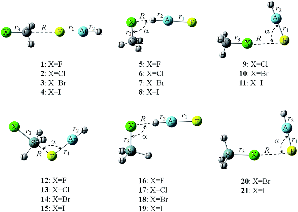 | ||
| Fig. 2 Structures of tetrel-, hydrogen-, and halogen-bonded complexes. | ||
| Type | R | ΔrAr–F | ΔrH–Ar | ΔrX–Y | α | |
|---|---|---|---|---|---|---|
| 1 | TB | 2.8271 | 0.0176 | −0.0075 | 0.0108 | 180.0 |
| 2 | TB | 2.8172 | 0.0190 | −0.0079 | 0.0119 | 180.0 |
| 3 | TB | 2.8032 | 0.0181 | −0.0079 | 0.0096 | 180.0 |
| 4 | TB | 2.8353 | 0.0169 | −0.0073 | 0.0076 | 180.0 |
| 5 | HB | 1.5374 | 0.1131 | 0.0063 | 0.0346 | 120.4 |
| 6 | HB | 1.9026 | 0.1143 | 0.0303 | 0.0171 | 94.5 |
| 7 | HB | 1.9951 | 0.1208 | 0.0432 | 0.0124 | 90.9 |
| 8 | HB | 2.1526 | 0.1243 | 0.0597 | 0.0064 | 87.7 |
| 9 | XB | 3.1979 | 0.0057 | −0.0021 | 0.0008 | 76.7 |
| 10 | XB | 2.9200 | 0.0155 | −0.0059 | 0.0027 | 86.8 |
| 11 | XB | 2.8178 | 0.0358 | −0.0131 | 0.0092 | 94.1 |
| 12 | TB | 1.9735 | 0.1617 | −0.0404 | 0.0581 | 103.3 |
| 13 | TB | 1.9032 | 0.2018 | −0.0435 | 0.1389 | 103.5 |
| 14 | TB | 1.8770 | 0.2196 | −0.0447 | 0.1674 | 103.2 |
| 15 | TB | 1.8497 | 0.2416 | −0.0455 | 0.2074 | 103.0 |
| 16 | HB | 1.6754 | 0.0823 | −0.0118 | 0.0333 | 180.0 |
| 17 | HB | 2.0093 | 0.0872 | 0.0122 | 0.0426 | 98.9 |
| 18 | HB | 2.0792 | 0.0977 | 0.0247 | 0.0433 | 93.3 |
| 19 | HB | 2.2132 | 0.1052 | 0.0432 | 0.0417 | 87.2 |
| 20 | XB | 3.1107 | 0.0102 | −0.0035 | −0.0030 | 84.0 |
| 21 | XB | 2.9653 | 0.0260 | −0.0092 | −0.0015 | 92.9 |
The interaction energies of the three types of interactions in these complexes are listed in Table 3. The MP2 interaction energies are calculated with three different basis sets – aug-cc-pVTZ, aug-cc-pVQZ, and with the complete basis set (CBS) extrapolation. In particular, for most complexes, the MP2/aug-cc-pVQZ results are very close to those in the CBS limit, indicating that these calculated interaction energies were converged. An exception is found for the tetrel-bonded complexes of SiH3X, which is attributed to the large deformation of SiH3X in the complexes. It should be noted that the geometries of SiH3X in the complexes were used to calculate the interaction energy of the tetrel-bonded complexes of SiH3X (12–15). For the CH3X complexes, the hydrogen-bonded complexes are most stable, while for the SiH3X complexes, the tetrel-bonded complexes are most stable, followed by the hydrogen-bonded complexes, and the weakest complexes are the halogen-bonded complexes. Clearly, the stability of the complex is dependent on the nature of both the X and Y atoms. As expected, the halogen bond becomes stronger for the heavier halogen atoms and CH3X is a stronger halogen donor than SiH3X, showing a consistent change with the most positive MEP on the halogen atom. However, the hydrogen bond is also stronger for the heavier halogen atom with the exception in 16, inconsistent with the most negative MEP on the halogen atom. This inconsistency indicates that the electrostatic interaction is not necessarily the only significant factor in determining the stability of hydrogen-bonded complexes. The interaction energy of the tetrel bond is almost the same in 1–3 although the most positive MEP on each carbon atom is clearly different. Moreover, the interaction energy of the tetrel bond in 12–15 becomes more negative with an increase of the halogen atomic number, which is inconsistent with the most positive MEP on the Si atom. This inconsistency may be related to the deformation of SiH3X in these complexes – notice that the normal tetrahedral geometry of SiH3X, evident in 16–21, is replaced by a trigonal bipyramidal geometry in 12–15, in which the Si and the three H atoms are almost in the same plane.
| Type | Aug-cc-pVTZ | Aug-cc-pVQZ | CBS | |
|---|---|---|---|---|
| 1 | TB | −16.28 | −16.20 | −16.16 |
| 2 | TB | −16.44 | −16.41 | −16.40 |
| 3 | TB | −16.13 | −16.17 | −16.19 |
| 4 | TB | −14.88 | −14.30 | −14.03 |
| 5 | HB | −31.17 | −31.13 | −31.11 |
| 6 | HB | −31.49 | −31.56 | −31.59 |
| 7 | HB | −32.08 | −32.25 | −32.33 |
| 8 | HB | −32.98 | −32.79 | −32.70 |
| 9 | XB | −6.19 | −6.54 | −6.70 |
| 10 | XB | −10.68 | −11.03 | −11.19 |
| 11 | XB | −19.75 | −19.59 | −19.52 |
| 12 | TB | −108.27 | −99.52 | −95.47 |
| 13 | TB | −136.75 | −123.37 | −117.18 |
| 14 | TB | −149.30 | −133.99 | −126.90 |
| 15 | TB | −162.99 | −143.94 | −135.12 |
| 16 | HB | −25.94 | −24.88 | −24.39 |
| 17 | HB | −23.42 | −22.86 | −22.60 |
| 18 | HB | −24.98 | −24.57 | −24.38 |
| 19 | HB | −27.23 | −26.41 | −26.03 |
| 20 | XB | −7.81 | −8.14 | −8.29 |
| 21 | XB | −14.36 | −14.35 | −14.35 |
The binding distance of the hydrogen bond becomes longer with an increase of the halogen atomic radius, while the reverse occurs for the binding distance of the halogen bond. The former change is inconsistent with the increase in the interaction energy, whereas the latter change is in agreement with the interaction energy trend. Thus the descriptive statement for the correlation between the interaction energy and the binding distance does not provide insightful arguments. It is noted that the binding distance is related to both the atomic radius and the interaction strength. The intermolecular separation (R) is substantially shorter in the hydrogen-bonded complexes compared with their halogen-bonded analogues, so the repulsion between SiH3X and HArF becomes more pronounced in the hydrogen-bonded dimers and limits how closely the subunits approach each other in these dimers. This may be why the change in R with increasing size of X is inconsistent for the more strongly-bound hydrogen-bonded species. The binding distance of the tetrel bond shows an irregular change in the CH3X complexes but shortens in the SiH3X complexes as the interaction becomes stronger. The binding distance is about 1.85 Å in 15, which is much shorter than the sum of the van der Waals radii of the respective atoms (about 3.57 Å)44 but is longer than the covalent length of the F–Si bond (about 1.56 Å). This suggests that the tetrel bond in the SiH3X complexes has some covalent character.
The increase in interaction energy (and corresponding decrease in binding distance) in 12–15 may be rationalized by considering that although the σ-hole arising from the Si atom of SiH3X decreases going from X = F to I (Table 1), the polarizability of SiH3X along the X–Si axis increases accordingly. Consequently, the dipole moment induced in SiH3X (along the X–Si axis) due to the electric field of the highly polar FArH molecule, will increase as X gets larger. This induced dipole can then interact favourably with the F lone pair of FArH oriented along the X–Si molecular axis. The large X–Si bond extension (increasing from F to I, Table 2) would also enhance the dipole–dipole interaction between SiH3X and FArH. We also note that in 12–15, the negatively charged H atoms of the SiH3 subunit (H is more electronegative than Si) all lie in the same plane so as to minimize the repulsion between these H atoms and the X and F (of FArH) lone pairs.
Whether for the associated bond in the halogen- and tetrel-bonded complexes or for the free bond in the hydrogen-bonded complexes, the ionic Ar–F bond is elongated in all complexes. In general, the elongation of the Ar–F bond correlates well with the interaction strength. Accordingly, the largest elongation of the Ar–F bond is found in the tetrel-bonded complexes of SiH3X. The associated H–Ar bond is lengthened in the hydrogen-bonded complexes, whereas the distant H–Ar bond is shortened in the halogen- and tetrel-bonded complexes. There is an exception for the hydrogen-bonded complex of SiH3F–HArF (16), where the H–Ar bond is compressed. The elongation of the H–Ar bond in the hydrogen bond shows some dependence on the interaction strength, but a prominent change with the increase of X atomic number is evident, in spite of the small change in the interaction energy. Also the contraction of the distant H–Ar bond correlates well with the strength of the halogen and tetrel bonds. The X–Y bond is stretched in all complexes except in the halogen-bonded complexes of SiH3Br–HArF (20) and SiH3I–HArF (21), in which a contraction occurs for the X–Y bond. Again, the largest stretching of X–Y bond is found in the tetrel-bonded complexes of SiH3X (12–15).
3.3 Frequency shifts
It is well-known that the H–Z stretch vibration usually exhibits a red shift in most hydrogen bonds, although there are also blue-shifting hydrogen bonds. The frequency shifts of Ar–F, H–Ar, and X–Y stretch vibrations are summarized in Table 4. Generally, these shifts are consistent with the change of the respective bond length. The Ar–F stretch vibration exhibits a red shift in all complexes, showing a coincident change in the strength of the corresponding interaction.| Type | ΔvAr–F | ΔvH–Ar | ΔvX–Y | |
|---|---|---|---|---|
| 1 | TB | −13 | 77 | −35 |
| 2 | TB | −14 | 80 | −28 |
| 3 | TB | −13 | 80 | −19 |
| 4 | TB | −13 | 74 | −13 |
| 5 | HB | −98 | −78 | −99 |
| 6 | HB | −106 | −333 | −38 |
| 7 | HB | −115 | −445 | −25 |
| 8 | HB | −123 | −598 | −15 |
| 9 | XB | −6 | 18 | 1 |
| 10 | XB | −15 | 54 | 2 |
| 11 | XB | −25 | 90 | 1 |
| 12 | TB | −97 | 434 | −138 |
| 13 | TB | −139 | 472 | −129 |
| 14 | TB | −165 | 486 | −339 |
| 15 | TB | −169 | 496 | −496 |
| 16 | HB | −76 | 153 | −81 |
| 17 | HB | −87 | −140 | −45 |
| 18 | HB | −103 | −268 | −27 |
| 19 | HB | −101 | −454 | −31 |
| 20 | XB | −10 | 32 | 3 |
| 21 | XB | −25 | 90 | 1 |
The H–Ar stretch vibration also displays a red shift in the hydrogen-bonded complexes except in 16. The red shift of the H–Ar stretch vibration in the hydrogen-bonded complexes of YH3X–HArF is the reverse of the blue shift of the H–Ar stretch vibration observed in the complexes of HArF with H2, N2, CO, and CO2.1–10 In the previous study for the frequency shift of the H–Ar stretch vibration, we found that it could be regulated by cooperative effects.10 We therefore infer that the red shift of the H–Ar stretch vibration in 5–8 and 17–19 is mainly due to the stronger hydrogen bond. Interestingly, the red shift of the H–Ar stretch vibration is strongly dependent on the nature of halogen atom although the corresponding interaction energies do not change significantly. This result is helpful in distinguishing the hydrogen bond formed by HArF with different molecules YH3X by means of infrared spectroscopy. On the other hand, the H–Ar stretch vibration shows a blue shift in the tetrel- and halogen-bonded complexes. This distant blue shift was also observed for other complexes of HArF.11 Moreover, it appears to be closely linked to the interaction strength. The largest blue shift (496 cm−1) is found in the tetrel-bonded complex of SiH3I–HArF, which is larger than the value obtained for the halogen-bonded complexes of HArF and dihalogen molecule,11 but smaller than the values for the beryllium-bonded complexes of HArF and BeH2.45 It is noted that the distant blue shift of the H–Ar stretch vibration is also large enough to be detected with experimental methods, perhaps by matrix isolation techniques.
In previous studies, a strong correlation was found between bond length change/frequency shift and the chemical “hardness” of the proton acceptor Y in X–H⋯Y complexes.46,47 In this model, the red shift is correlated with decreasing hardness (or increasing polarizability) of the atom to which the H is bonded, while a blue shift is correlated with increasing hardness.46,47 This model may explain the increasing H–Ar red shift (and bond elongation) for SiH3X–HArF dimers (17–19) and the H–Ar blue shift (and bond compression) in SiH3F–HArF (16). Note that the polarizability along the Si–F axis will be the smallest (and the F atom, the hardest) in the latter dimer, favouring an H–Ar blue shift. This should be compared with the side-on SiH3X–HArF dimers, for which the hardness decreases with increasing size of X (Cl > Br > I) and the polarizability (as measured by the polarizability components perpendicular to the Si–X bond axis) increases accordingly, favouring a steadily increasing red shift (and bond elongation) for these complexes.
The X–Y stretch vibration exhibits a red shift in the tetrel- and hydrogen-bonded complexes, while its shift is very small in the halogen-bonded complexes. Furthermore, the red shift of the X–Y stretch vibration becomes smaller with the increase of X atomic mass in 1–8 and 16–19, due to the heavier mass of the X atom. However, this red shift increases going from SiH3Cl to SiH3I in the tetrel-bonded complexes of SiH3X–HArF. We ascribe this tendency to the stronger tetrel bond.
3.4 AIM analyses
Fig. 3 shows the molecular maps of the complexes between HArF and SiH3Br. The existence of tetrel, hydrogen, and halogen bonds is characterized by Si⋯F, H⋯Br, and Br⋯F bond critical points (BCPs), respectively. In the halogen-bonded complex 20, there is also a Br⋯Ar BCP, providing an evidence for a weak Br−⋯Ar+ interaction. Since Kr has a larger positive charge in HKrF than Ar does in HArF, it is expected that a Br⋯Kr BCP (corresponding to a stronger Br−⋯Kr+ interaction) should be obtained for the analogous SiH3Br⋯HKrF complex, which has been confirmed in Fig. S1.† Actually, the Br−⋯Ar+ interaction is also present in the halogen-bonded complex 7 since the Br atom in CH3Br has a larger Vmin(Br) than that in SiH3Br. This interaction in 7 and 20 can be evidenced by the non-covalent interactions (NCI) map in Fig. S2,† where a green area is observed between the Br and Ar atoms. The electron density, Laplacian, and energy density at these BCPs are collected in Table 5. The electron density ranges from 0.006 to 0.067 au in the complexes, which is partly in the range 0.002–0.04 au as suggested for hydrogen bonds by Koch and Popelier.48 The electron density in 4–8 and 12–19 is out of this range, suggesting the presence of stronger interactions in these complexes. The electron density at the Y⋯F BCP increases with an increase of X atomic mass, which disagrees with the interaction energy trend for the C⋯F tetrel bond, but agrees with the interaction energy trend for the Si⋯F tetrel bond. The electron densities in the hydrogen and halogen bonds are not compared due to the different types of BCP. The value of the Laplacian at the Si⋯F BCP is much larger than those for the other BCPs. The energy density is negative for 4–8 and 12–19, but is positive for the other complexes. The positive energy density corresponds to a predominantly closed-shell interaction,49 whereas the negative energy density means that the corresponding interaction has a partially covalent character.49 | ||
| Fig. 3 Molecular maps of tetrel- (14), hydrogen- (18), and halogen- (20) bonded complexes of SiH3Br–HArF. | ||
| Type | ρ | ∇2ρ | H | |
|---|---|---|---|---|
| 1 | TB | 0.0081 | 0.0459 | 0.0022 |
| 2 | TB | 0.0087 | 0.0475 | 0.0023 |
| 3 | TB | 0.0092 | 0.0487 | 0.0023 |
| 4 | TB | 0.0095 | 0.0441 | 0.0019 |
| 5 | HB | 0.0562 | 0.1302 | −0.0159 |
| 6 | HB | 0.0529 | 0.0310 | −0.0189 |
| 7 | HB | 0.0535 | 0.0120 | −0.0195 |
| 8 | HB | 0.0538 | 0.0115 | −0.0158 |
| 9 | XB | 0.0060 | 0.0268 | 0.0013 |
| 10 | XB | 0.0126 | 0.0534 | 0.0018 |
| 11 | XB | 0.0192 | 0.0756 | 0.0018 |
| 12 | TB | 0.0493 | 0.2719 | −0.0051 |
| 13 | TB | 0.0585 | 0.3628 | −0.0054 |
| 14 | TB | 0.0624 | 0.4039 | −0.0056 |
| 15 | TB | 0.0669 | 0.4513 | −0.0058 |
| 16 | HB | 0.0365 | 0.1210 | −0.0042 |
| 17 | HB | 0.0400 | 0.0482 | −0.0102 |
| 18 | HB | 0.0430 | 0.0316 | −0.0123 |
| 19 | HB | 0.0428 | 0.0162 | −0.0121 |
| 20 | XB | 0.0093 | 0.0372 | 0.0014 |
| 21 | XB | 0.0152 | 0.0580 | 0.0017 |
3.5 NBO analyses
The interactions in these complexes have also been analyzed by considering the orbital interactions. It was found that there is an orbital interaction of LpF → BD*X–Y in the tetrel and halogen bonds but LpX → BD*H–Ar in the hydrogen bond. The orbital interaction LpF → BD*X–Y was not found in 12–15 due to the formation of a Si–F bond. These orbital interactions are estimated using the second-order perturbation energies in Table 6. One can see that the hydrogen bond has a strong orbital interaction, characterized by large perturbation energies. For the hydrogen bond, the strong orbital interaction also reflects a sizeable covalent contribution. The perturbation energy of the LpX → BD*H–Ar orbital interaction has a similar trend to that for the interaction energy of the hydrogen bond, but the former trend is more prominent than the latter. The perturbation energy is smaller in 1–4, 9–11, and 20–21, and is also consistent with the trend for the interaction energy of the halogen bond.| Type | E2 | qHArF | ΔσH–Ar | Δσ*H–Ar | |
|---|---|---|---|---|---|
| a E2 corresponds to the orbital interaction of LpF → BD*X–Y in TB and XB, LpX → BD*H–Ar in HB. | |||||
| 1 | TB | 6.19 | 0.0040 | 0.0000 | −0.0117 |
| 2 | TB | 7.06 | 0.0056 | −0.0001 | −0.0123 |
| 3 | TB | 7.86 | 0.0063 | −0.0001 | −0.0123 |
| 4 | TB | 7.34 | 0.0061 | −0.0001 | −0.0116 |
| 5 | HB | 172.13 | −0.0582 | −0.0014 | 0.0007 |
| 6 | HB | 291.76 | −0.1323 | 0.0002 | 0.0728 |
| 7 | HB | 354.46 | −0.1685 | 0.0002 | 0.1075 |
| 8 | HB | 404.41 | −0.2097 | 0.0011 | 0.1486 |
| 9 | XB | 2.47 | 0.0034 | −0.0002 | −0.0026 |
| 10 | XB | 13.12 | 0.0090 | −0.0003 | −0.0081 |
| 11 | XB | 35.03 | 0.0189 | −0.0003 | −0.0190 |
| 12 | TB | — | 0.1360 | −0.0030 | −0.0621 |
| 13 | TB | — | 0.1619 | −0.0025 | −0.0702 |
| 14 | TB | — | 0.1706 | −0.0023 | −0.0733 |
| 15 | TB | — | 0.1793 | −0.0021 | −0.0766 |
| 16 | HB | 74.70 | −0.0268 | −0.0010 | −0.0199 |
| 17 | HB | 187.77 | −0.0847 | 0.0000 | 0.0369 |
| 18 | HB | 252.43 | −0.1201 | 0.0010 | 0.0682 |
| 19 | HB | 302.30 | −0.1596 | 0.0011 | 0.1053 |
| 20 | XB | 4.60 | 0.0038 | −0.0003 | −0.0052 |
| 21 | XB | 15.17 | 0.0106 | −0.0003 | −0.0138 |
The sum of the atomic charges on HArF (qHArF) is also given in Table 6. The qHArF value is negative for the hydrogen bond but positive for the tetrel and halogen bonds. With the increase of halogen atomic mass, qHArF becomes more negative or positive in all complexes, except in 4. This indicates that the charge transfer is important in the formation of these complexes. The magnitude of charge transfer is particularly large in 4–8 and 12–19.
Upon complexation, the charge densities in the H–Ar bonding and anti-bonding orbitals are changed. One can see in Table 6 that the charge density in the H–Ar bonding orbital changes only slightly but for the H–Ar anti-bonding orbital, relatively large changes are obtained. Specifically, the charge density in the H–Ar anti-bonding orbital is decreased in the tetrel and halogen bonds, while it is increased in the hydrogen bond except in 16. The decrease of charge density in the H–Ar anti-bonding orbital leads to an enhancement of the H–Ar bond, leading to the contraction of the H–Ar bond and a blue shift. On the other hand, the increase of charge density in the H–Ar anti-bonding orbital results in a weakening of the H–Ar bond, being responsible for its elongation and corresponding red shift.
3.6 Energy decomposition analyses
To gain a better understanding of the origin of the stability of these complexes, the interaction energy was decomposed into five components: the electrostatic energy (ES), exchange energy (EX), repulsion energy (REP), polarization energy (POL), and dispersion energy (DISP).43 The corresponding results are presented in Table 7. The interaction energies in Tables 3 and 7 are almost equal for most complexes except 5–8, 11, and 15–19. The reason for their deviations is that the optimized geometries of the monomers are used in Table 3 used to compute the interaction energies in Table 3, whereas the geometries that the monomers adopt in the optimized complexes are used to compute the interaction energies in Table 7. It is expected that the electrostatic energy is largest for the stronger halogen bond in 11 and 21. For the moderate halogen bond in 10 and 20, the three attractive terms of ES, POL and DISP make comparable contributions. However, DISP makes a larger contribution than ES to the weak halogen bond in 9.| ES | EX | REP | POL | DISP | |
|---|---|---|---|---|---|
| 1 | −23.37 | −19.86 | 32.94 | −5.85 | −0.46 |
| 2 | −22.82 | −22.91 | 37.95 | −7.44 | −1.38 |
| 3 | −22.82 | −24.87 | 41.17 | −8.32 | −1.13 |
| 4 | −20.15 | −24.20 | 39.79 | −8.90 | −1.17 |
| 5 | −79.80 | −99.32 | 194.70 | −57.43 | 3.18 |
| 6 | −61.70 | −116.66 | 223.96 | −77.66 | −7.02 |
| 7 | −60.99 | −126.90 | 244.49 | −88.74 | −8.44 |
| 8 | −53.21 | −130.79 | 250.63 | −99.69 | −10.58 |
| 9 | −6.06 | −18.39 | 31.64 | −4.60 | −8.86 |
| 10 | −18.81 | −42.93 | 74.15 | −10.78 | −12.50 |
| 11 | −45.31 | −83.14 | 145.26 | −23.62 | −14.21 |
| 12 | −277.89 | −360.27 | 694.21 | −160.34 | −4.56 |
| 13 | −340.75 | −425.19 | 831.28 | −204.03 | 1.00 |
| 14 | −368.72 | −454.20 | 892.60 | −224.47 | 4.89 |
| 15 | −405.04 | −495.71 | 979.25 | −250.93 | 10.62 |
| 16 | −58.06 | −58.14 | 111.90 | −32.23 | 5.73 |
| 17 | −43.26 | −84.98 | 160.89 | −53.88 | −8.11 |
| 18 | −45.65 | −100.32 | 191.15 | −66.84 | −10.07 |
| 19 | −41.93 | −109.39 | 207.79 | −79.67 | −12.62 |
| 20 | −10.45 | −28.76 | 48.86 | −7.23 | −10.41 |
| 21 | −29.85 | −61.49 | 105.46 | −16.55 | −12.67 |
ES contributes more to the stability of the tetrel-bonded complexes than POL and DISP in 1–4. Moreover, the ES term has a consistent change with the most positive MEP on the C atom. For the tetrel bond in 12–15, there is a large EX, which corresponds to a substantial overlap between the molecular orbitals, evidenced by the strong orbital interactions. This large EX is accompanied by a large REP due to the close contact between the two molecules, as confirmed by the shorter binding distances. The ES term is also larger than the POL term in 12–15, although both contributions are quite large. The large POL contribution means that the orbitals undergo a significant change in their shapes, which is typical for the formation of a covalent bond. In addition, both ES and POL terms become more negative with an increase of halogen atomic number. The results above show that the tetrel bond is dominated by the electrostatic interaction but nonetheless also exhibits the characteristics of a covalent interaction. It is also found that 12–15 show substantially larger ES than the other complexes, consistent with the relatively larger positive MEP on the Si atom than on the C and halogen atoms.
For the hydrogen bond, with the increase of halogen atomic number, ES is less negative but POL is more negative. The POL contribution exceeds that of ES in most hydrogen bonds. The decrease of ES accords with the change of the most negative MEP on the halogen atom. Therefore, the hydrogen bond is governed by a combination of electrostatic and polarization energies, and the polarization contribution even exceeds that of the electrostatic energy in most cases. Additionally, the contributions from EX and REP should not be ignored. DISP is positive in 5 and 13–16, which is unfavorable for the stability of these complexes. The positive dispersion energy in these complexes is caused by the differences in the intra- and interionic correlation energy on going from noninteracting to interacting molecules.43 It has been shown that the dispersion energy is sensitive to the binding distance,43 from the positive one to the negative one when the distance is longer. The binding distance is very short in these complexes, being responsible for the positive DISP.
4. Conclusions
A theoretical study of the tetrel-, hydrogen-, and halogen-bonded complexes formed by HArF with YH3X (X = halogen, Y = C and Si) has been undertaken by means of ab initio MP2 computational methods. The energetic results show that the HB complexes are favored in the CH3X complexes while the TB complexes are the most stable of the SiH3X complexes. Interestingly, most complexes become more stable with an increase of the halogen atomic mass.The vibrational analysis of these complexes showed a significant red shift of the H–Ar bond, between 78 and 598 cm−1, in the hydrogen-bonded complexes, whereas a sizeable blue shift was found in the complexes with halogen bond and tetrel bonds. These shifts have a pronounced change when the halogen is varied, particularly in the hydrogen-bonded complexes, although the interaction energy only changes slightly. Consequently, it should be possible for these complexes to be detected and distinguished using spectroscopic methods, perhaps by matrix isolation techniques.
The NBO and AIM analyses showed that the tetrel bond in the SiH3X complexes and the hydrogen bond in all complexes have a partially covalent nature. The energy decomposition analyses indicated that the interactions above are jointly governed by electrostatic and polarization forces. The relative contribution of each energy component to the stability of the halogen bond is apparently dependent on how strong the halogen bond is.
Acknowledgements
This work was supported by the National Natural Science Foundation of China (21573188).References
- M. Solimannejad and I. Alkorta, Chem. Phys. Lett., 2007, 439, 284–287 CrossRef CAS.
- S. A. C. McDowell, Chem. Phys., 2004, 301, 53–60 CrossRef CAS.
- S. A. C. McDowell, Chem. Phys. Lett., 2003, 368, 649–653 CrossRef CAS.
- S. A. C. McDowell, Mol. Phys., 2004, 102, 71–77 CrossRef CAS.
- S. A. C. McDowell, Chem. Phys. Lett., 2005, 406, 228–231 CrossRef CAS.
- M. Solimannejad and I. Alkorta, Chem. Phys., 2006, 324, 459–464 CrossRef CAS.
- A. V. Nemukhin, B. L. Grigorenko, L. Khriachtchev, H. Tanskanen, M. Pettersson and M. Räsänen, J. Am. Chem. Soc., 2002, 124, 10706–10711 CrossRef CAS PubMed.
- S. A. C. McDowell, J. Chem. Phys., 2005, 122, 204309 CrossRef PubMed.
- H. Tanskanen, S. Johansson, A. Lignell, L. Khriachtchev and M. Räsänen, J. Chem. Phys., 2007, 127, 54313 CrossRef PubMed.
- X. F. Liu, Q. Z. Li, J. B. Cheng and W. Z. Li, Mol. Phys., 2013, 111, 497–504 CrossRef CAS.
- Q. Z. Li, Z. B. Liu, B. Jing, W. Z. Li, J. B. Cheng, B. A. Gong and J. Z. Sun, Spectrochim. Acta, Part A, 2010, 77, 506–511 CrossRef PubMed.
- L. Khriachtchev, M. Pettersson, N. Runeberg, J. Lundell and M. Räsänen, Nature, 2000, 406, 874–876 CrossRef CAS PubMed.
- L. Khriachtchev, M. Pettersson, A. Lignell and M. Räsänen, J. Am. Chem. Soc., 2001, 123, 8610–8611 CrossRef CAS PubMed.
- M. Pettersson, L. Khriachtchev, A. Lignell, M. Räsänen, Z. Bihary and R. B. Gerber, J. Chem. Phys., 2002, 116, 2508–2515 CrossRef CAS.
- L. Graham, O. Graudejus, N. K. Jha and N. Bartlett, Coord. Chem. Rev., 2000, 197, 321–334 CrossRef CAS.
- J. J. Turner and G. C. Pimentel, Science, 1963, 140, 974–975 CAS.
- D. S. Brock, V. Bilir, H. P. A. Mercier and G. J. Schrobilgen, J. Am. Chem. Soc., 2007, 129, 3598–3611 CrossRef CAS PubMed.
- L. Khriachtchev, K. Isokoski, A. Cohen, M. Räsänen and R. B. Gerber, J. Am. Chem. Soc., 2008, 130, 6114–6118 CrossRef CAS PubMed.
- L. Khriachtchev, H. Tanskanen, J. Lundell, M. Pettersson, H. Kiljunen and M. Räsänen, J. Am. Chem. Soc., 2003, 125, 4696–4697 CrossRef CAS PubMed.
- J. Lundell and M. Pettersson, Phys. Chem. Chem. Phys., 1999, 1, 1691–1697 RSC.
- J. Lundell, S. Berski and Z. Latajka, Phys. Chem. Chem. Phys., 2000, 2, 5521–5527 RSC.
- A. V. Nemukhin, B. L. Grigorenko, L. Khriachtchev, H. Tanskanen, M. Pettersson and M. Räsänen, J. Am. Chem. Soc., 2002, 124, 10706–10711 CrossRef CAS PubMed.
- S. A. C. McDowell, Phys. Chem. Chem. Phys., 2003, 5, 808–811 RSC.
- S. A. C. McDowell, Chem. Phys., 2004, 301, 53–60 CrossRef CAS.
- A. Lignell, J. Lundell, L. Khriachtchev and M. Räsänen, J. Phys. Chem. A, 2008, 112, 5486–5494 CrossRef CAS PubMed.
- S. A. C. McDowell, J. Chem. Phys., 2004, 121, 5728–5732 CrossRef CAS PubMed.
- M. Solimannejad and A. Boutalib, Chem. Phys., 2006, 320, 275–280 CrossRef CAS.
- X. F. Liu, Q. Z. Li, R. Li, W. Z. Li and J. B. Cheng, Spectrochim. Acta, Part A, 2011, 84, 68–73 CrossRef CAS PubMed.
- Q. Z. Li, J. L. Zhao, R. Li, W. Z. Li, J. B. Cheng and B. A. Gong, Comput. Theor. Chem., 2011, 970, 61–65 CrossRef CAS.
- X. F. Liu, J. B. Cheng, Q. Z. Li and W. Z. Li, Spectrochim. Acta, Part A, 2013, 101, 172–177 CrossRef CAS PubMed.
- A. Bauzá and A. Frontera, Angew. Chem., Int. Ed., 2015, 54, 7340–7343 CrossRef PubMed.
- A. Bauzá, T. J. Mooibroek and A. Frontera, Angew. Chem., Int. Ed., 2013, 52, 12317–12321 CrossRef PubMed.
- S. B. Choi, B. K. Kim, P. Boudjouk and D. G. Grier, J. Am. Chem. Soc., 2001, 123, 8117–8118 CrossRef CAS PubMed.
- N. W. Mitzel and U. Losehand, Angew. Chem., Int. Ed., 1997, 36, 2807–2809 CrossRef CAS.
- S. J. Grabowski, Phys. Chem. Chem. Phys., 2014, 16, 1824–1834 RSC.
- D. Mani and E. Arunan, Phys. Chem. Chem. Phys., 2013, 15, 14377–14383 RSC.
- M. J. Frisch, G. W. Trucks, H. B. Schlegel, G. E. Scuseria, M. A. Robb, J. R. Cheeseman, J. A. Montgomery Jr, T. Vreyen, K. N. Kudin, J. C. Burant, J. M. Millam, S. S. Iyengar, J. Tomasi, V. Barone, B. Mennucci, M. Cossi, G. Scalmani, N. Rega, G. A. Petersson, H. Nakatsuji, M. Hada, M. Ehara, K. Toyota, R. Fukuda, J. Hasegawa, M. Ishida, T. Nakajima, Y. Honda, O. Kitao, H. Nakai, M. Klene, X. Li, J. E. Knox, H. P. Hratchian, J. B. Cross, C. Adamo, J. Ja ramillo, R. Gomperts, R. E. Stratmann, O. Yazyev, A. J. Austin, R. Cammi, C. Pomelli, J. W. Octhterski, P. Y. Ayala, K. Morokuma, G. A. Voth, P. Salvador, J. J. Dannenberg, V. G. Zakrzewski, S. Dapprich, A. D. Daniels, M. C. Strain, O. Farkas, D. K. Malick, A. D. Rabuck, K. Raghavachari, J. B. Foresman, J. V. Ortiz, Q. Cui, A. G. Baboul, S. Clifford, J. Cioslowski, B. B. Stefanov, G. Liu, A. Liashenko, P. Piskorz, I. Komaromi, R. L. Martin, D. J. Fox, T. Keith, M. A. Al Laham, C. Y. Peng, A. Nanayakkara, M. Challacombe, P. M. W. Gill, B. Johnson, W. Chen, M. W. Wong, C. Gonzalez and J. A. Pople, Gaussian 09, Revision A.02, Gaussian, Inc., Wallingford CT, 2009 Search PubMed.
- S. F. Boys and F. Bernardi, Mol. Phys., 1970, 19, 553–566 CrossRef CAS.
- F. A. Bulat, A. Toro-Labbé, T. Brinck, J. S. Murray and P. Politzer, J. Mol. Model., 2010, 16, 1679–1691 CrossRef CAS PubMed.
- R. F. W. Bader, AIM2000 Program, v. 2.0, McMaster University, Hamilton, Canada, 2000 Search PubMed.
- A. E. Reed, L. A. Curtiss and F. A. Weinhold, Chem. Rev., 1988, 88, 899–926 CrossRef CAS.
- M. W. Schmidt, K. K. Baldridge, J. A. Boatz, S. T. Elbert, M. S. Gordon, J. H. Jensen, S. Koseki, N. Matsunaga, K. A. Nguyen, S. J. Su, T. L. Windus, M. Dupuis and J. A. Montgomery, J. Comput. Chem., 1993, 14, 1347–1363 CrossRef CAS.
- P. F. Su and H. Li, J. Chem. Phys., 2009, 13, 014102 CrossRef PubMed.
- A. Bondi, J. Phys. Chem., 1964, 68, 441–451 CrossRef CAS.
- Q. Z. Li, X. F. Liu, R. Li, J. B. Cheng and W. Z. Li, Spectrochim. Acta, Part A, 2012, 90, 135–140 CrossRef CAS PubMed.
- A. D. Buckingham, J. E. Del Bene and S. A. C. McDowell, Chem. Phys. Lett., 2008, 463, 1–10 CrossRef CAS.
- S. A. C. McDowell and A. J. Thakkar, Int. J. Quantum Chem., 2010, 110, 1506–1513 CAS.
- U. Koch and P. L. A. Popelier, J. Phys. Chem. A, 1995, 99, 9747–9754 CrossRef CAS.
- W. D. Arnold and E. Oldfield, J. Am. Chem. Soc., 2000, 122, 12835–12841 CrossRef CAS.
Footnote |
| † Electronic supplementary information (ESI) available: Fig. S1 and S2. See DOI: 10.1039/c5ra23556a |
| This journal is © The Royal Society of Chemistry 2016 |