Enhanced oil-fouling resistance of poly(ether sulfone) membranes by incorporation of novel amphiphilic zwitterionic copolymers†
Guangfa Zhang,
Fan Gao,
Qinghua Zhang*,
Xiaoli Zhan and
Fengqiu Chen
College of Chemical and Biological Engineering, Zhejiang University, Hangzhou, Zhejiang 310027, PR China. E-mail: qhzhang@zju.edu.cn; Fax: +86-571-8795-1227; Tel: +86-571-8795-3382
First published on 5th January 2016
Abstract
In this study, a novel amphiphilic copolymer, poly(carboxyl betain methyl acrylamide-co-3,3,4,4,5,5,6,6,7,7,8,8,8-tridecafluorooctyl acrylate) P(CBMA-co-TFOA), with zwitterionic and fluorinated moieties was synthesized by free radical polymerization and a subsequent quaternization reaction. The synthesized copolymers acted as additives and were blended with poly(ether sulfone) (PES) to fabricate low oil-fouling PES membranes through nonsolvent induced phase separation (NIPS). The prominent surface enrichment of hydrophilic zwitterionic (CBMA) and low surface energy (TFOA) segments on the membrane surface was verified by X-ray photoelectron spectroscopy (XPS), water contact angle measurements and surface energy analysis. The excellent oil-fouling resistant capacity of these modified membranes was demonstrated by oil/water emulsion separation tests. In particular, membrane PES/P3, with the optimized hydrophilic and hydrophobic ratio, achieved the highest anti-oil-fouling properties with a total flux decay as low as 17.4% (nearly no irreversible flux-decline) and high flux recovery (99.3%) after simple water flushing. These desirable antifouling properties are believed to originate from the binary-cooperative effect of zwitterionic and low surface energy microdomains. Moreover, three-cycle oil/water separation tests and underwater immersion experiments further revealed that the as-prepared membranes have remarkable antifouling stability. The results of this study provide a new insight into the surface chemical heterogeneity–antifouling property relationships of membranes for efficient oil/water separation.
1. Introduction
Oil/water separation is a worldwide challenge due to the ever-increasing amounts of industrial oily wastewater and increasing environmental awareness.1,2 Traditional remediation techniques, including oil skimmers, sedimentation, and flotation, are useful for separation of immiscible oil/water mixtures, but are not effective for emulsified oil/water mixtures and also suffer from low efficiency, high costs as well as secondary pollution.3,4 Recently, membrane processes have shown great promise as a clean and efficient technology for oily wastewater treatment owing to their potential advantages of being simple systems with short process times and high oil-removal efficiencies.5 However, membrane fouling because of surfactant adsorption and pore plugging by oil droplets is a major obstacle, which limits the wide application of membrane technologies for oily wastewater treatment.6,7Many previous studies have shown that enhancing surface hydrophilicity by introducing hydrophilic moieties such as poly(ethylene glycol) (PEG)-based polymers can effectively reduce membrane fouling.8 The hydration of hydrophilic moieties plays an important role in the antifouling mechanism (fouling-resistant), which can prevent the foulants from attaching to the surface by constructing a compact hydration layer barrier and robust steric repulsion force on the surface.9,10 Although hydrophilic modification of surfaces is one of the most widely used approaches to effectively resist bio-fouling, it is not capable of completely stopping oil-fouling. Compared with other bio-foulants, such as bacteria and protein, oil droplets have lower surface tension and higher viscosity; therefore, they can more readily approach and adhere on the hydrophilic membrane surfaces (with high surface energy).11 Oil contamination is difficult to remove once adsorbed and thus leads to the loss of their oil/water separation function as well.12,13 Accordingly, there is an urgent need to fabricate effective and practical oil/water separation membranes. Amphiphilic surfaces comprising both hydrophilic and low surface energy (hydrophobic) microdomains have proven to be a desirable and ideal strategy for antifouling application due to their collaborative antifouling mechanism of fouling-resistant and fouling-release.14 The core of the fouling-release mechanism is to weaken or minimize the interfacial bond between foulants and surfaces so that attached foulants can be easily removed by the hydrodynamic shear forces.15 The low surface energy fluorine/siloxane-containing polymers have been widely used as fouling-release coating materials. Especially, fluorinated polymers with remarkable bulk properties, including chemical resistance, thermostability, and low refractive index, are becoming a popular antifouling material.16 To date, numerous heterogeneous amphiphilic coatings have been fabricated and used in the marine-antifouling field.17–19 For example, van Zoelen et al. fabricated fluorinated amphiphilic polymer coatings with excellent antifouling properties against the algae Ulva linza and Navicula diatoms.20 Therefore, amphiphilic membrane surfaces combining synergistically hydrophilic and low surface energy moieties might also be effective in resisting oil-fouling.
Poly(ethylene glycol) (PEG)-based materials have been extensively used as the hydrophilic polymer or hydrophilic chains of amphiphilic copolymers due to their intrinsic higher hydration capacity and commercial availability. However, there is a fatal limit for the further application of PEG-based polymers because of their oxidative degradation.21 In contrast, zwitterionic materials, integrating both positively and negatively charged units in one group, such as phosphorylcholine, sulfobetaine, and carboxybetaine polymers, are a promising candidate for hydrophilic antifouling materials due to their higher chemical stability.22 It has also been demonstrated that the zwitterions show stronger hydration capacity via the electrostatic interaction compared to polyethylene glycol (PEG) achieving hydration via hydrogen bonding.23–25 As discussed above, we are thus motivated to fabricate an amphiphilic membrane surface by incorporating both zwitterionic carboxybetaine (CBMA) and fluorinated 3,3,4,4,5,5,6,6,7,7,8,8,8-tridecafluorooctyl acrylate (TFOA) segments via blending modification to deter the oil-fouling for effective oil/water separation. To date, sparse studies have been reported regarding the amphiphilic copolymer additive composing of zwitterionic and fluorinated segments used for membrane oil-fouling resistant modification.26 Zhang et al. reported the synthesis of a novel amphiphilic zwitterionic copolymer, poly(vinylidene fluoride)-graft-poly(sulfobetaine methacrylate) (PVDF-g-PSBMA), as an amphiphilic copolymer additive for the preparation of PVDF membranes.27 Even though improved hydrophilicity and anti-fouling properties were observed for this approach, it was not effective in preventing oil-fouling by purely hydrophilic modification. Another study reported hierarchically engineered PVDF membrane surfaces by a facile surface segregation approach with amphiphilic copolymers consisting of zwitterionic poly[3-(methacryloyl-amino)propyl]-dimethyl (3-sulfopropyl) ammonium hydroxide (PSPP) and fluorine-containing hydrophobic poly(hexafluorobutylmethacrylate) (PHFBM) segments as an additive.28 However, the resultant PVDF membrane was shown to have a surface free energy of above 40 mJ m−2 due to the short fluorocarbon chain in the fluorinated polymers, indicating that the fouling-release property of constructed membrane surfaces still remained unsatisfactory for practical oil/water separation applications.
In this study, a novel amphiphilic zwitterionic copolymer, P(CBMA-co-TFOA), was prepared by facile free radical polymerization and subsequent quaternization reaction with bromoacetic acid (BAA). The copolymer was then blended with PES to prepare PES blend membranes by conventional wet phase-inversion method. During the coagulating process, both zwitterionic and fluorinated segments were segregated freely from the membrane surface by surface segregation phenomenon, which was confirmed by X-ray photoelectron spectroscopy (XPS), contact angle measurement and energy-dispersive spectroscopy (EDS). The oil-fouling resistance property of membranes was evaluated by oil/water separation experiment using 1000 ppm oil-in-water emulsion as a model solution. The integrated-defense mechanism (fouling-resistant and fouling-release) was intensively explored by regulating the hydrophilic/low surface energy moieties mole ratios in the amphiphilic copolymers. Moreover, long-term antifouling stability and durability of these membranes were also assessed.
2. Materials and methods
2.1. Materials
Poly(ether sulfone) (PES, A100, Mw = 52![[thin space (1/6-em)]](https://www.rsc.org/images/entities/char_2009.gif) 000 g mol−1) was obtained from Solvay Advanced Polymers and dried at 100 °C for 12 h before use. N-[3-(Dimethylamino) propyl] methacrylamide (DMAPMA, Aladdin) and 3,3,4,4,5,5,6,6,7,7,8,8,8-tridecafluorooctyl acrylate (TFOA, 99.9%, Aldrich) were filtered through a basic alumina column to remove the radical inhibitor. Bromoacetic acid (BAA) was purchased from Aladdin and used as received. 2,2′-Azobisiso-butyronitrile (AIBN, Aldrich) was recrystallized from ethanol. Petroleum ether (60–90 °C), N,N-dimethylformamide (DMF), and dimethyl sulfoxide (DMSO) were obtained from Sinopharm Chemical Reagent and used as received. High-speed vacuum pump oil (GS-1) was purchased from Beijing Sifang Special Oil Factory. Sodium dodecyl sulfate (SDS) and acetonitrile were of analytical grade and were all purchased from the local reagent corporation.
000 g mol−1) was obtained from Solvay Advanced Polymers and dried at 100 °C for 12 h before use. N-[3-(Dimethylamino) propyl] methacrylamide (DMAPMA, Aladdin) and 3,3,4,4,5,5,6,6,7,7,8,8,8-tridecafluorooctyl acrylate (TFOA, 99.9%, Aldrich) were filtered through a basic alumina column to remove the radical inhibitor. Bromoacetic acid (BAA) was purchased from Aladdin and used as received. 2,2′-Azobisiso-butyronitrile (AIBN, Aldrich) was recrystallized from ethanol. Petroleum ether (60–90 °C), N,N-dimethylformamide (DMF), and dimethyl sulfoxide (DMSO) were obtained from Sinopharm Chemical Reagent and used as received. High-speed vacuum pump oil (GS-1) was purchased from Beijing Sifang Special Oil Factory. Sodium dodecyl sulfate (SDS) and acetonitrile were of analytical grade and were all purchased from the local reagent corporation.
2.2. Synthesis of the amphiphilic zwitterionic copolymer
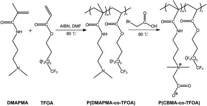
Amphiphilic zwitterionic copolymers, P(CBMA-co-TFOA), were synthesized by a two-step synthesis method. As illustrated in Scheme 1, an amphiphilic precursor, P(DMAPMA-co-TFOA), was firstly synthesized via a facile free radical polymerization. The PDMAPMA chains of P(DMAPMA-co-TFOA) were then quaternized by reacting with bromoacetic acid (BAA) and thus the amphiphilic zwitterionic copolymers P(CBMA-co-TFOA) were obtained. Taking P2 as a typical example, TFOA (8 g), DMAPMA (8 g), and N,N-dimethylformamide (DMF, 37.33 g) were added into a 100 mL three-necked flask fitted with a nitrogen inlet and outlet. The solution was purged with N2 for 30 min to remove oxygen, and then AIBN (0.24 g) was added into the abovementioned solution. The polymerization was carried out at 80 °C for 24 h under a nitrogen atmosphere and then terminated by cooling to about 0 °C. After polymerization, the product copolymer was isolated by precipitation into excess ice ether and petroleum ether mixture (ether/petroleum ether, v/v = 2/5) and recovered by centrifugation. The amphiphilic copolymer P(DMAPMA-co-TFOA) was obtained after being dried in a vacuum oven at 40 °C overnight.Subsequently, the abovementioned P(DMAPMA-co-TFOA) (2 g) and DMF (8 g) were added into a 50 mL three-necked flask fitted with a nitrogen inlet and outlet, and the solution was purged with N2 for 30 min. Excess bromoacetic acid (1.7 g) dissolved in acetonitrile (5.3 g) was prepared separately and added dropwise into the solution containing P(DMAPMA-co-TFOA). Furthermore, the reaction mixture was stirred for 48 h at 80 °C under nitrogen to convert the amine group into a quaternary ammonium group. The resultant polymer solution was precipitated with abundant ice ether and then dried under vacuum at 45 °C for 24 h. The as-prepared P(CBMA-co-TFOA) copolymers with different composition were labeled as P1, P2, and P3, and their actual molar compositions in the copolymer are summarized in Table 1. In addition, we also prepared the homopolymer of PCBMA (named as P0), which only shows the hydrophilic property, according to a similar procedure. The successful preparation of these copolymers was further verified by Fourier transform infrared (FTIR) spectrometry, 1H nuclear magnetic resonance (1H NMR) spectrometry, and gel permeation chromatography (GPC, Waters 1525/2414) measurements.
2.3. Membrane preparation and characterization
The PES blend membranes were prepared by the nonsolvent induced phase separation (NIPS) method. Casting solutions contained 18 wt% PES, 2 wt% P(CBMA-co-TFOA) and 80 wt% DMSO. The solutions were stirred for 12 h at 60 °C and then degassed for another 12 h to completely release the bubbles. The casting solution was then cast on a glass plate using a blade with a gap height of 200 μm and immediately immersed into a water-coagulating bath at 30 °C. The as-formed membranes were fully rinsed with deionized water and stored in deionized water for at least 24 h to remove the residual solvent. In addition, the virgin PES (PEG400 as pore-forming agent) and purely hydrophilic modification PES/P0 membrane (PCBMA as modifier) were prepared as control membranes following a similar procedure. The as-made membranes modified with amphiphilic copolymers P1, P2, and P3 were named as PES/P1, PES/P2, PES/P3, respectively.The morphologies (surface, cross-section) and element mapping of investigated membranes were characterized using scanning electron microscopy (SEM, SIRION-100, FEI Co., Ltd.) and energy-dispersive spectroscopy (EDS), respectively. The surface chemistry composition of the investigated membranes was characterized by X-ray photoelectron spectroscopy (XPS, VG ESCALAB MARK II spectrometer) with a standard Mg Kα X-ray source (1253.6 eV). Contact angle (CA) measurements upon the membrane surfaces were carried out by a CAM200 optical contact angle meter (KSV Co., Ltd.) under a sessile mode at 25 °C, and the decaying of the static CA was recorded. In this study, two polar liquids (water and glycerol), two nonpolar liquids (hexadecane and high-speed vacuum pump oil, GS-1) were chosen as the test liquids. For each membrane sample, the reported result was the average of at least seven measurements. The total surface tension of membranes were calculated from the static contact angles according to the Owens and Wendt's29 two-liquid geometric method and three-liquid Lifshitz-van der Waals acid–base model.30
In order to evaluate the surface pore size of membranes, molecular weight cut-off experiments were conducted by measuring the rejection of dextran (70, 250, and 500 kDa).31 The concentrations of feed and permeate dextran solution were determined by UV-vis spectrophotometry to calculate the rejections.10 The zeta potential of membrane surfaces was measured by a Sur-PASS electrokinetic analyzer (Anton Paar GmbH, Austria). The measurements were performed in a background electrolyte solution containing 1 M KCl at pH 7 and 25 °C. The zeta potential was calculated according to Helmholtz–Smoluchowski equation.32
2.4. Ultrafiltration experiments and antifouling properties evaluation
Surfactant-stabilized oil-in-water emulsion (GS-1, high-speed vacuum oil 0.9 g L−1 and SDS 0.1 g L−1) was employed as the model foulant solution for antifouling properties evaluation. The ultrafiltration experiment was carried out with a dead-end stirred cell (model 8200, Millipore Co., effective membrane area was 28.7 cm2) and conducted at the pressure of 0.15 MPa and the stirring speed of 200 rpm. The permeate flux J (L m−2 h−1) for each membrane was computed as follows: J = V/AΔt, where V (L) is the volume of permeated water, A (m2) is the membrane effective area, and Δt (h) is the permeation time. Each membrane was initially compacted for about 30 min at 0.20 MPa to obtain a stable flux and then the pressure was lowered to the operation pressure of 0.15 MPa. The entire filtration process encompassed three steps: first-round pure water filtration (0.5 h), model oil-in-water solution filtration (1 h) and with deionized water cleaning for about 30 min, finally the second-round pure water filtration (0.5 h).For antifouling property evaluation, the initial pure water flux of Jw1 (L m−2 h−1), the permeate flux of model feed solutions Jp (L m−2 h−1), and the permeate flux of the cleaned membranes Jw2 (L m−2 h−1) were analyzed in detail. Moreover, the solute rejection (R) was calculated according to the equation R = 1 − Cp/Cf, where Cp and Cf (g L−1) are the concentration of foulants in permeate and feed solutions, respectively. The concentrations of oil-in-water emulsion were quantified using UV absorbance at 531 nm. Furthermore, to examine the antifouling properties of the investigated membranes in detail, the total flux-decline ratio (DRt = 1 − Jp/Jw1), reversible flux-decline ratio (DRr = (Jw2 − Jp)/Jw1), irreversible flux-decline ratio (DRir = (Jw1 − Jw2)/Jw1), and flux recovery ratio (FRR = Jw2/Jw1) were defined and discussed in this study.
2.5. Evaluation of antifouling stability
The cyclic filtration process of oil/water emulsion included three cycles. In each individual cycle, 0.5 h pure-water permeation was performed, followed by 1 h oil-in-water emulsion separation. Between the two cycles, the membrane surface was rinsed with deionized water for 20 min. The pure-water permeation, oil-in-water emulsion separation, and cleaning process together were considered as an individual cycle. The cycle was repeated three times to systematically investigate the membrane anti-fouling stability.The long-term surface composition and antifouling stability of as-prepared membranes were evaluated by immersing the modified membranes in pure water during 1, 3, 6, and 9 days. Furthermore, the contact angles of water and hexadecane on the immersed membranes were measured and analyzed in detail.
3. Results and discussion
3.1. Synthesis of the amphiphilic zwitterionic copolymer, P(CBMA-co-TFOA)
The chemical structure and composition of the synthesized amphiphilic copolymer, P(CBMA-co-TFOA), were investigated by FTIR and 1H NMR spectroscopy. As shown in Fig. 1a, the absorption band at 1740 cm−1 was ascribed to –C![[double bond, length as m-dash]](https://www.rsc.org/images/entities/char_e001.gif) O stretching vibration of the ester group in PTFOA. The peak intensity of the –C
O stretching vibration of the ester group in PTFOA. The peak intensity of the –C![[double bond, length as m-dash]](https://www.rsc.org/images/entities/char_e001.gif) O bonds significantly increased with the increase of the PTFOA content in the amphiphilic copolymers. The broad absorption band at around 3357 cm−1 was assigned to the stretching vibration of –NH (amide groups) and carboxylic –OH in PCBMA. It can be noted that the decreased intensity of the broad absorption band (at 3357 cm−1) of P3 may be due to the decreased content of PDMAPMA in copolymer P3. The peak at 1634 cm−1 corresponds to the stretching vibration of –C–O (amide groups) and –C
O bonds significantly increased with the increase of the PTFOA content in the amphiphilic copolymers. The broad absorption band at around 3357 cm−1 was assigned to the stretching vibration of –NH (amide groups) and carboxylic –OH in PCBMA. It can be noted that the decreased intensity of the broad absorption band (at 3357 cm−1) of P3 may be due to the decreased content of PDMAPMA in copolymer P3. The peak at 1634 cm−1 corresponds to the stretching vibration of –C–O (amide groups) and –C![[double bond, length as m-dash]](https://www.rsc.org/images/entities/char_e001.gif) O (carboxyl groups) in PCBMA. The results clearly indicate that the quaternary amination reaction using bromoacetic acid was successfully achieved. In addition, the peaks corresponding to the stretching vibrations of –CF2 bonds in PTFOA occurred in the region between 1160 and 1266 cm−1. These results basically revealed that the amphiphilic zwitterionic copolymers P(CBMA-co-TFOA) had been successfully synthesized.
O (carboxyl groups) in PCBMA. The results clearly indicate that the quaternary amination reaction using bromoacetic acid was successfully achieved. In addition, the peaks corresponding to the stretching vibrations of –CF2 bonds in PTFOA occurred in the region between 1160 and 1266 cm−1. These results basically revealed that the amphiphilic zwitterionic copolymers P(CBMA-co-TFOA) had been successfully synthesized.
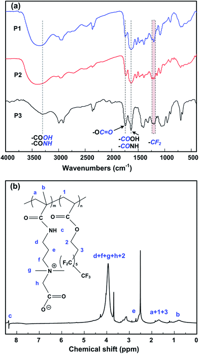 | ||
| Fig. 1 (a) FTIR spectra of amphiphilic zwitterionic copolymers, P(CBMA-co-TFOA) (P1, P2, and P3) and (b) 1H NMR spectra of the representative P1 copolymer. | ||
The detail chemical compositions of the amphiphilic ionic copolymers were further measured by 1H NMR spectroscopy. As presented in Fig. 1b, the peak at 2.5 ppm is a characteristic chemical shift for the deuterated solvent DMSO. The peaks observed at 1.67 and 0.78 ppm were assigned to the –CH2 and –CH3 groups for the CBMA and TFOA units, respectively. There is one –CH2 group in each CBMA unit and two –CH2 groups in each TFOA unit, whereas one –CH3 group in each CBMA unit. Thus, the actual mole composition of PTFOA components in the amphiphilic copolymers can be calculated according to the peak intensities at 1.67 and 0.78 ppm and the results are summarized in Table 1. In addition, results of molecular weight of synthesized polymers determined by GPC are also listed in the Table 1. Obviously, the numerical values of these amphiphilic copolymers are relatively small, and it should be mentioned that the measured data are lower than the actual values. One plausible explanation is the fact that TFOA units tend to self-assemble in THF (GPC eluent) to form micelles owing to its intrinsic association.33
3.2. Characterization of membrane morphology and surface chemistry
The effect of amphiphilic copolymer addition on membrane morphology was investigated by SEM. Fig. 2A shows the cross-section morphology of neat PES and modified membranes. It can be observed that all membrane samples exhibit a typical asymmetric structure with a dense skin layer and a finger-like porous sub-layer. For the PES/P1 and PES/P2 membranes, it can be observed that the finger-like microvoids decrease in thickness, and there are much larger circular voids close to the back side of these membranes in comparison with the control PES membrane. This can be explained by the pore-forming ability of hydrophilic PCBMA segments in amphiphilic polymer additives (P1 and P2).34 In contrast, for PES/P3, the finger-like microvoids increase in thickness; however, no obvious circular voids are observed at the bottom of the membrane. It indicates that the pore-forming ability of copolymer P3 is not significant due to the lower content of hydrophilic zwitterionic segments in P3. In order to further investigate the surface pore sizes and rejection characteristics of membranes, molecular weight cut-off (MWCO) experiments were performed using dextran as the solute molecule. As shown in Fig. S1 (ESI†), the MWCO of PES, PES/P1, PES/P2, and PES/P3 are about 200, 350, 280, and 110 kDa (at 90% rejection), respectively, indicating that the pore size of the blend membranes is in the following sequence: PES/P1 > PES/P2 > PES > PES/P3. As reported by Andrew, the average pore size of membranes can be calculated according to the MWCO values when the average molecular weight and approximate diameters of dextrans are known,35 thus these membrane MWCO approximately correspond to pore diameters of 13, 16, 18, and 22 nm for PES/P3, PES, PES/P2, and PES/P1, respectively. This indicated that the introduction of amphiphilic copolymers (especially P1 and P2) resulted in membranes with greater surface pore size, which was also verified by the SEM images presented in Fig. 2B. Moreover, the bulk porosity of the investigated membranes determined by dry-wet method is in agreement with the corresponding SEM images (Table S2, ESI†).36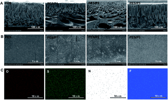 | ||
| Fig. 2 (A) Cross-section and (B) on-top surface SEM images of the investigated membranes (PES, PES/P1, PES/P2, PES/P3). (C) EDS mapping analysis of the PES/P3 membrane top surface. | ||
The elemental distribution of the PES/P3 membrane on the top surface was characterized by EDS mapping analysis (Fig. 2C). It clearly revealed that N, F, O, and S were homogeneously dispersed on the surface of the PES/P3 membrane. The presence of N was ascribed to PCBMA segments, whereas F was derived from the PTFOA segments. These results successfully confirmed the enrichment of the amphiphilic zwitterionic copolymer on the modified membrane surface.
3.3. Surface chemical composition
The surface composition of modified membranes with amphiphilic functional polymer segments incorporated onto membrane surfaces was determined by XPS analysis. From the data of Fig. 3a, XPS characteristic signals, corresponding at around 284.8 eV (C1s), 531.7 eV (O1s), and 167.7 eV (S2p) were observed for all investigated membranes. The presence of the N1s characteristic signal (399.6 eV) on the PES/P0 membrane surface was due to the free surface segregation of the hydrophilic PCBMA segments. Meanwhile, the F (688.5 eV) and N (399.6 eV) characteristic signals were observed for amphiphilic modified membranes (PES/P1, PES/P2, and PES/P3), illustrating that the successful formation of surface heterogeneity derived from the amphiphilic zwitterionic copolymer additives. As presented in Table 2, with the increase of fluorine amount in amphiphilic copolymers, the surface F elemental mole percentages increased significantly.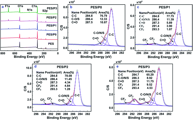 | ||
| Fig. 3 XPS wide-scan spectra of the investigated membranes (a), C1s core level spectra resolving results of the PES/P0 membrane (b), PES/P1 membrane (c), PES/P2 membrane (d), and PES/P3 membrane (e). | ||
| Membranes | Surface elemental compositiona (mol%) | Surface segment coveragea (mol%) | |||||
|---|---|---|---|---|---|---|---|
| C | O | S | N | F | ΦXPSCBMA | ΦXPSTFOA | |
| a The mean of triplicate analysis. | |||||||
| PES | 74.3 ± 1.2 | 20.2 ± 0.8 | 5.6 ± 0.5 | — | — | — | — |
| PES/P0 | 71.9 ± 1.0 | 18.8 ± 0.6 | 4.5 ± 0.4 | 4.9 ± 0.5 | — | 37.5 ± 0.3 | — |
| PES/P1 | 70.6 ± 0.8 | 19.2 ± 0.9 | 4.6 ± 0.5 | 3.4 ± 0.3 | 2.2 ± 0.2 | 26.8 ± 0.2 | 11.8 ± 0.2 |
| PES/P2 | 71.4 ± 1.1 | 17.7 ± 0.7 | 4.9 ± 0.3 | 3.0 ± 0.2 | 3.0 ± 0.3 | 23.2 ± 0.2 | 14.1 ± 0.3 |
| PES/P3 | 62.3 ± 0.7 | 15.7 ± 0.4 | 3.4 ± 0.3 | 2.5 ± 0.3 | 16.2 ± 0.5 | 22.2 ± 0.3 | 49.8 ± 0.3 |
For further determination of the quantitative information, XPS C1s core level spectra were fitted with five curves representing different chemical environments by shape analysis using Gaussian–Lorentzian fitting functions: binding energy locating at around 284.8 eV for C–C, 286.4 eV for C–O, C–N or C–S, 287.3 eV for C![[double bond, length as m-dash]](https://www.rsc.org/images/entities/char_e001.gif) O, 291.4 eV for –CF2, and 293.3 eV for –CF3, as shown in Fig. 3. Because the PTFOA segments were the only source of –CF3 moieties, the near-surface coverage of PTFOA (ΦTFOA) for modified membranes could be calculated according to the following equation:
O, 291.4 eV for –CF2, and 293.3 eV for –CF3, as shown in Fig. 3. Because the PTFOA segments were the only source of –CF3 moieties, the near-surface coverage of PTFOA (ΦTFOA) for modified membranes could be calculated according to the following equation:
 | (1) |
![[double bond, length as m-dash]](https://www.rsc.org/images/entities/char_e001.gif) O, ACF2, and ACF3 are the areas of the fitted C–C, C–O, C
O, ACF2, and ACF3 are the areas of the fitted C–C, C–O, C![[double bond, length as m-dash]](https://www.rsc.org/images/entities/char_e001.gif) O, –CF2, and –CF3 peaks, respectively. The factor 1/11 was the theoretical mole ratio of –CF3 in each TFOA repeat unit. On the other hand, since PCBMA segments was the only source of nitrogen for the PES blend membranes, the near-surface coverage of PCBMA (ΦCBMA) could be computed from the XPS signal intensities of nitrogen and carbon based on the following equation:
O, –CF2, and –CF3 peaks, respectively. The factor 1/11 was the theoretical mole ratio of –CF3 in each TFOA repeat unit. On the other hand, since PCBMA segments was the only source of nitrogen for the PES blend membranes, the near-surface coverage of PCBMA (ΦCBMA) could be computed from the XPS signal intensities of nitrogen and carbon based on the following equation:| ΦCBMA = 11N/2C | (2) |
The corresponding surface coverages of PTFOA and PCBMA segments on the membrane surfaces are summarized in Table 2.
It was observed that the value of ΦPEG for the PES/P0 membrane was as high as 37.5 ± 0.3 mol%. With the increasing content of PTFOA segments in the amphiphilic modifiers, the values of ΦCBMA on the membrane surfaces showed a slightly decreasing trend, whereas the values of ΦTFOA remarkably increased. During the phase inversion process, the diffusion exchange of solvent and non-solvent would trigger the precipitation of polymer. Due to the intrinsic superior hydrophilicity and low interfacial free energy with water, the hydrophilic PCBMA segments were prone to migrate to the polymer–water interface during the coagulating process via free surface segregation.37,38 The hydrophobic PTFOA segments could not spontaneously segregate onto the polymer–water interface and tended to be trapped in the matrix polymer owing to their hydrophobic interaction and high interface energy with water.28 However, in this study, the amphiphilic additives of P(CBMA-co-TFOA) in which low surface energy PTFOA segments covalently bonding with hydrophilic PCBMA segments were intentionally tailored. Thus, the hydrophobic PTFOA segments were readily dragged onto membrane surfaces by hydrophilic PCBMA segments via “forced surface segregation”, resulting in the desired surface enrichment of hydrophobic PTFOA segments on the membrane surfaces. Based on the enrichment of both the hydrophilic PCBMA and low surface energy PTFOA segments on surfaces, the PES membrane with heterogeneous surface compositions was achieved by a simple one-step blending modification.
3.4. Membrane surface wetting properties
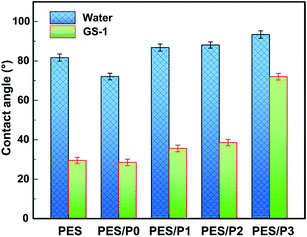
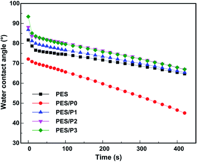
The permeation and anti-fouling properties of the membranes are mainly dependent on their surface wettability. By introducing zwitterionic and fluorine-containing segments on the membrane surfaces, we can manipulate both the surface wetting characteristics and the surface energy. Fig. 4 shows the water and oil contact angles of the investigated membrane surfaces. The water contact angle of the PES/P0 membrane was smaller than that of the control PES membrane, suggesting that the presence of zwitterionic segments improved the hydrophilicity of the membrane surface. For amphiphilic PES blend membranes, the water contact angles were slightly increased due to the combined action of hydrophilic zwitterionic segments and hydrophobic fluorine-containing segments. On the other hand, the oil contact angle of the PES/P0 membrane was 28.5° and slightly lower than that of the virgin PES membrane (29.5°). More importantly, with the incorporation of the fluorinated PTFOA segments on membrane surfaces, the oil contact angle of the membranes (PES/P1, PES/P2, and PES/P3) was considerably increased, indicating the enhanced oleophobicity.In the case of the amphiphilic membrane surface, the static contact angle was not in an equilibrium state and it would decrease over time.39 To further evaluate the surface heterogeneity, the dynamic change of water contact angles was recorded. As shown in Fig. 5, after 600 s, the water contact angle of the control PES membrane decreased modestly from 81.7° to 58.5° due to its intrinsic hydrophobicity. For the amphiphilic PES modified membranes, the decay values of water contact angle became much higher than that of the neat PES membrane. In particular, the contact angle of the PES/P0 membrane exhibited the highest decaying speed decreasing from 72.1° to 29.4°, which was due to the obvious migration of zwitterionic segments onto the membrane surfaces. The variation of water contact angle on the porous membrane surfaces is mainly influenced by capillary absorption, roughness, and heterogeneity.39 Considering that the pore size of all the membranes was similar (in a range of 13–22 nm), its effect on capillary absorption could be negligible. Therefore, the different decay tendency can be mainly ascribed to the surface heterogeneity and the migration of polar PCBMA segments from the subsurface region to the water/membrane interface.40
The membrane surface free energy was also determined by the contact angles of probe liquids (water, glycerol, and hexadecane). The surface energy parameters of investigated membranes were calculated using two-liquid geometric model and three-liquid Lifshitz-van der Waals acid–base model, as summarized in Table 3. According to the two-liquid model, the total surface energy and polar components of the control PES membrane were 33.1 and 5.9 mJ m−2, respectively. Both the surface energy and polar component of the PES/P0 membrane were significantly increased, which was due to the presence of the highly polar zwitterionic segments with the electrostatically induced hydration potential.24,41 In addition, both the total surface energies and polar components (γps) of amphiphilic PES membranes were obviously decreased as the surface coverage of PTFOA segments increased. These results can be attributed to the nonpolar low surface energy nature of PTFOA segments, indicating the thermodynamic unfavorable adhesion with membrane foulants.42,43 In particular, the PES/P3 membrane with the highest surface content of PTFOA segments achieved a minimum value of 23.4 and 3.5 mJ m−2 for the total surface energy and polar component, respectively. It was also found that, as shown in Table 3, the similar results were obtained using the three-liquid Lifshitz-van der Waals acid–base model. The surface energy results are in well agreement with XPS and contact angle measurements.
| Membranes | Two-liquid modela (mJ m−2) | Three-liquid modelb (mJ m−2) | |||||
|---|---|---|---|---|---|---|---|
| γs | γds | γps | γs | γLWs | γ+s | γ−s | |
a Two-liquid model: γs = γds + γps, γL(1 + cos![[thin space (1/6-em)]](https://www.rsc.org/images/entities/char_2009.gif) θ) = 2(γdLγds)1/2 + 2(γpLγps)1/2.b Three-liquid model: θ) = 2(γdLγds)1/2 + 2(γpLγps)1/2.b Three-liquid model:  . . |
|||||||
| PES | 33.08 ± 0.80 | 27.21 ± 0.10 | 5.87 ± 0.80 | 32.21 ± 0.70 | 27.21 ± 0.06 | 1.11 ± 0.10 | 5.62 ± 0.70 |
| PES/P0 | 37.80 ± 1.00 | 27.23 ± 0.10 | 10.58 ± 0.90 | 35.82 ± 0.80 | 27.23 ± 0.05 | 1.70 ± 0.20 | 10.86 ± 0.90 |
| PES/P1 | 30.70 ± 0.70 | 26.68 ± 0.20 | 4.02 ± 0.60 | 28.80 ± 0.50 | 26.68 ± 0.10 | 0.20 ± 0.05 | 5.72 ± 0.70 |
| PES/P2 | 29.70 ± 0.70 | 25.96 ± 0.20 | 3.74 ± 0.40 | 27.15 ± 0.60 | 25.96 ± 0.20 | 0.06 ± 0.03 | 6.25 ± 0.60 |
| PES/P3 | 23.42 ± 0.90 | 19.89 ± 0.40 | 3.53 ± 0.50 | 20.38 ± 0.04 | 19.89 ± 0.40 | 0.01 ± 0.01 | 7.54 ± 0.70 |
3.5. Zeta potential measurements
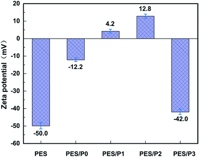
In order to characterize the surface charge characteristics of the membranes, the zeta potential was measured. As presented in Fig. 6, the zeta potential of the control PES membrane was −50.0 mV (measured at pH 7.4), which is consistent with the isoelectric point at pH 4.9 reported in the previous study.44 For PES/P0, the surface zeta potential had a much higher value of −12.2 mV. This can be attributed to the intrinsic balanced oppositely charged groups of PCBMA on the membrane surface.45 Remarkably, with the enrichment of both zwitterionic and PTFOA segments on membrane surfaces, the zeta potential values of modified membranes were initially increased and then decreased. This phenomenon can be explained by the combined effects of both zwitterionic with nearly electric neutrality and fluorinated groups with strong electronegative.46 When the content of fluorinated units is relatively lower, the zwitterionic layer plays an extremely important role on deciding the surface charge, whereas the zeta potential decreased sharply as the fluorinated segments significantly increased on the membrane surface. On the other hand, the positive values of zeta potential for the copolymers P1 and P2 could also be related with the residual tertiary amino that did not fully convert into the zwitterionic groups (Table S1, ESI†). The higher surface charge will generally lead to greater electrostatic interaction between the foulants and membrane surfaces, resulting in an aggravation of membrane fouling. Accordingly, the decreased zeta potential is advantageous to the improvement of antifouling ability of PES blend membranes. It should also be noted that if the membrane with greater surface charge was applied to selectively separate charged proteins, it will be attractive due to its high separation efficiency. These results of zeta potential also further confirmed the effective distributions of zwitterionic and PTFOA segments on the PES blend surfaces.3.6. Membrane oil-fouling resistant properties
As a result of its eco-friendliness, high operation efficiency, and energy-saving technical advantages, pressure-driven filtration by porous membranes has become a highly competitive candidate for water reclamation. It is generally accepted that porous membrane surfaces encounter more arduous challenges in inhibiting surface fouling because convective flow through membranes can aggravate foulants migration and the formation of pore blocking.47 In this study, to investigate the synergistic fouling-resistant and fouling-release properties of the membranes, the oil/water emulsion separation experiments were conducted in a dead-end filtration module. Membrane fouling usually consists of reversible fouling and irreversible fouling. The reversible fouling is mainly ascribed to reversible foulants deposition and weak interaction between the foulants and membrane surface, which could be recovered by simple hydraulic washing and probably released from membrane surfaces with the aid of near-surface agitation.10 While the irreversible fouling is primarily caused by the intractable adsorption of foulants on membrane surfaces or the entrapment of foulants in pore channels, which is extremely difficult or impossible to recover.48 To analyze the antifouling properties of the investigated membranes in detail, total flux-decline ratio (DRt), reversible flux-decline ratio (DRr), irreversible flux-decline ratio (DRir), and flux recovery ratio (FRR) were defined according to the time-dependent flux variations during the filtration process. Thus, lower DRir (higher FRR, FRR = 100% − DRir) represented better fouling-resistant capacity, whereas lower DRr (lower DRt) indicated a better fouling-release property.The permeability and selectivity of the membranes could be evaluated by oil-in-water emulsion filtration experiments, and the pure water flux and oil rejection results are listed in Table S4 (ESI†). The permeability of membrane is believed to mainly dependent on the surface hydrophilicity, surface pore size, and bulk porosity. As shown in Table S4,† the water permeate flux of PES/P0 achieved a maximum value of 149.7 L m−2 h−1, which was due to the highest surface hydrophilicity. In comparison to the virgin PES membrane, PES/P1 had a higher water permeability, which was attributed to the increased surface pore size and membrane porosity, as discussed in MWCO experiments. As for PES/P2 and PES/P3, the decreased surface hydrophilicity obviously increased the resistance of water permeating through membrane and thus the permeability showed a significant decreasing trend. Furthermore, the separation efficiency of all membranes toward oil droplets was more than 99.4% (showed in the Table S4†), indicating a much high separation ability. It can be noted that the separation selectivity of modified membranes (PES/P1 and PES/P2) showed a slight decrease compared to the virgin PES membrane. This phenomenon can be explained by the slight increase of surface pore sizes of PES blend membranes (see SEM images, Fig. 2).
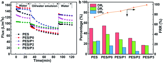
The time-dependent fluxes of the investigated membranes are presented in Fig. 7. For the control PES membrane, DRr and DRir were as high as 24.3% and 25.5%, corresponding to DRt as high as 49.8% and FRR as low as 74.5%, indicating both poor antifouling and fouling-release properties. This result was primarily attributed to its intrinsic hydrophobic and thus stronger hydrophobic interaction between oil droplets and the membrane surface. As for the hydrophilic PES/P0 membrane, the flux recovery ratio (FRR) was increased to 83.7%, suggesting an enhanced fouling resistant property by the surface hydrophilic modification. However, the total flux-decline ratio (DRt) and reversible flux-decline ratio (DRr) were up to 54.6% and 38.3%, respectively, which was larger than that of neat PES membrane. This unusual phenomenon was due to the higher surface energy of the PES/P0 membrane, which made oil droplets more readily adhere to the membrane surface.
In comparison, the irreversible flux-decline ratio (DRir) was considerably suppressed after introducing both hydrophilic zwitterionic and low surface energy segments on the membrane (PES/P1, PES/P2, PES/P3) surfaces, revealing that the fouling-resistant ability was remarkably improved. Moreover, with the increase of PTFOA content in amphiphilic copolymer additives, the total flux-decline ratio (DRt) and reversible flux-decline ratio (DRr) were significantly decreased. In particular, the PES/P3 membrane achieved the best comprehensive antifouling property: only 16.7% reversible flux-decline and nearly no irreversible flux-decline, corresponding to 17.4% total flux-decline and 99.3% flux recovery. These results indicated that the amphiphilic PES blend membranes showed a desirable synergistic antifouling performance with the aid of heterogeneous microdomains on the membrane surfaces.
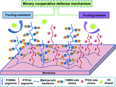
A schematic of the binary cooperative defense mechanism for heterogeneous PES membranes is shown in Fig. 8. The PES/Pn (n = 1, 2, 3) membrane surfaces comprising both hydrophilic (zwitterionic) and low surface energy microdomains endowed the membranes with optimal antifouling capacities. The hydrophilic zwitterionic segments caused the formation of powerful hydration layer barrier via electrostatic interaction, thereby to avoid the direct contact between foulants and membrane surfaces, which provided excellent antifouling ability for the surfaces. On the other hand, low surface energy segments facilitated the formation of non-adhesive microdomians to minimize the interaction between emulsified oil droplets and surfaces, which rendered the surfaces with desirable fouling-release property. The findings suggested that membranes synergistically manipulated with surface heterogeneity (both hydrophilic and low surface energy segments) have a good potential to effectively eliminate oil-fouling for oily water treatment.
3.7. Antifouling stability and durability of membranes
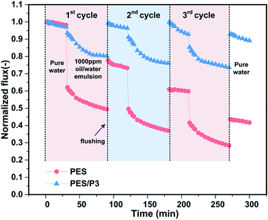
Considering the complexity in practical application, the long-term antifouling stability of these modified membranes was investigated by cyclic oil/water filtration tests. As shown in Fig. 9, in order to compare the flux recovery/antifouling performance of virgin and modified membranes, all the permeation fluxes were normalized by the first-cycle pure water flux of Jw1 and defined as a normalized flux. It was revealed that the normalized flux of oil/water emulsion through the control PES membrane gradually attenuated from 50.2% to 37.7% to 28.9% for the first, second, and third cycle, respectively. Moreover, the flux recovery ratios after each cycle for control PES membrane also declined sharply. In contrast, the normalized flux of the PES/P3 membrane only decreased slightly from 82.6% to 78.3% to 75.8% after each cycle. More importantly, the flux recovery ratios after each cycle for PES/P3 membrane were still kept at a higher value, which were more than 91.8%. Results indicated that amphiphilic PES/P3 membrane showed excellent antifouling durability in long-term operation process compared to the virgin PES membrane.In addition, the surface composition and antifouling sustainability of as-prepared membranes were also evaluated by the consecutive contact angle monitoring during membrane long-term underwater immersion. As can be seen from Fig. 10, the water contact angles on the PES/P0 membrane significantly increased from 72.1° to 78.7°after one day underwater immersion, whereas the water contact angles on PES/P3 membrane remained almost unchanged. The noticeable difference of surface modification stability was mainly attributed to the different anchoring strength of additives. The highly hydrophilic zwitterionic polymer is usually prone to leach out from membrane matrix due to its poor compatibility with PES, resulting in the loss of surface hydrophilicity.10,45 It can be noted that hydrophobic PTFOA segments in amphiphilic zwitterionic copolymers can firmly be anchored in the PES matrix via hydrophobic interactions, endowing the PES/P3 membrane with a higher stability of amphiphilic modification surfaces.38 Similar conclusions can be obtained for hexadecane contact angles shown in the Fig. 10. Therefore, the as-prepared membranes modified with amphiphilic zwitterionic copolymers show excellent durability in modification validity and have promising prospects for practical applications.
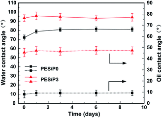 | ||
| Fig. 10 Water and hexadecane contact angles of the PES/P0 and PES/P3 membranes after immersing different days in water. | ||
4. Conclusions
In summary, a novel amphiphilic zwitterionic copolymer P(CBMA-co-TFOA) composed of zwitterionic and fluorinated segments was synthesized by the free radical polymerization method and subsequent quaternization reaction. An amphiphilic PES membrane was facilely fabricated by blending with the resulting copolymers through conventional NIPS method. During the phase inversion process, both zwitterionic and low surface energy segments migrated spontaneously onto membrane surfaces by surface segregation, which was confirmed by the XPS, surface wettability and energy-dispersive spectroscopy (EDS) measurements. The as-prepared membrane surfaces thus exhibited obvious composition heterogeneity containing hydrophilic and hydrophobic domains. The modified membrane displayed dramatically enhanced oil-fouling resistance compared with the virgin PES membrane. The membrane of PES/P3 achieved the best anti-oil-fouling property, i.e., the total flux decay was remarkably decreased to 17.4% (nearly no irreversible flux-decline) and high flux recovery of 99.3% after simple water flushing. The binary-cooperative effect of fouling-resistant mechanism (zwitterionic) and fouling-release mechanism (low surface energy) mainly accounted for the low oil-fouling membrane surfaces. Along with the prominent antifouling stability, the as-fabricated membranes show promising prospects for effective oil/water separation.Acknowledgements
We are grateful for the financial supports from the National Natural Science Foundation of China (No. 21176212, 21276224, 21476195) and the Zhejiang Provincial Natural Science Foundation of China (LY14B060008).References
- A. V. Dudchenko, J. Rolf, L. Shi, L. Olivas, W. Y. Duan and D. Jassby, ACS Nano, 2015, 9, 9930 CrossRef CAS.
- Y. Si, Q. X. Fu, X. Q. Wang, J. Zhu, J. Y. Yu, G. Sun and B. Ding, ACS Nano, 2015, 9, 3791 CrossRef CAS.
- G. Kwon, A. K. Kota, Y. Li, A. Sohani, J. M. Mabry and A. Tuteja, Adv. Mater., 2012, 24, 3666 CrossRef CAS.
- F. Zhang, W. B. Zhang, Z. Shi, D. Wang, J. Jin and L. Jiang, Adv. Mater., 2013, 25, 4192 CrossRef CAS.
- T. Yuan, J. Q. Meng, T. Y. Hao, Z. H. Wang and Y. F. Zhang, ACS Appl. Mater. Interfaces, 2015, 7, 14896 CAS.
- B. Chakrabarty, A. K. Ghoshal and M. K. Purkait, J. Membr. Sci., 2008, 325, 427 CrossRef CAS.
- Z. Shi, W. B. Zhang, F. Zhang, X. Liu, D. Wang, J. Jin and L. Jiang, Adv. Mater., 2013, 25, 2422 CrossRef CAS.
- J. Zhu, X. Z. Zhao and C. J. He, RSC Adv., 2015, 5, 53653 RSC.
- X. Chen, G. F. Zhang, Q. H. Zhang, X. L. Zhan and F. Q. Chen, Ind. Eng. Chem. Res., 2015, 54, 3813 CrossRef CAS.
- F. Gao, G. F. Zhang, Q. H. Zhang, X. L. Zhan and F. Q. Chen, Ind. Eng. Chem. Res., 2015, 54, 8789 CrossRef CAS.
- K. He, H. R. Duan, G. Y. Chen, X. K. Liu, W. S. Yang and D. Y. Wang, ACS Nano, 2015, 9, 9188 CrossRef CAS.
- Z. L. Chu, Y. J. Feng and S. Seeger, Angew. Chem., Int. Ed., 2015, 54, 2328 CrossRef CAS.
- L. B. Zhang, Y. J. Zhong, D. Cha and P. Wang, Sci. Rep., 2013, 3, 2326 Search PubMed.
- W. J. Chen, Y. L. Su, J. M. Peng, Y. N. Dong, X. T. Zhao and Z. Y. Jiang, Adv. Funct. Mater., 2011, 21, 191 CrossRef CAS.
- X. T. Zhao, Y. L. Su, H. Dai, Y. F. Li, R. N. Zhang and Z. Y. Jiang, J. Mater. Chem. A, 2015, 3, 3325 CAS.
- Y. N. Zhou, J. J. Li and Z. H. Luo, Ind. Eng. Chem. Res., 2015, 2043316644 Search PubMed.
- C. S. Gudipati, C. M. Greenlief, J. A. Johnson, P. Prayongpan, K. L. Wooley and J. Polym, J. Polym. Sci., Part A: Polym. Chem., 2004, 42, 6193 CrossRef CAS.
- C. S. Gudipati, J. A. Finlay, J. A. Callow, M. E. Callow and K. L. Wooley, Langmuir, 2005, 21, 3044 CrossRef CAS.
- Z. L. Zhao, H. G. Ni, Z. Y. Han, T. F. Jiang, Y. J. Xu, X. L. Lu and P. Ye, ACS Appl. Mater. Interfaces, 2013, 5, 7808 CAS.
- W. van Zoelen, H. G. Buss, N. C. Ellebracht, N. A. Lynd, D. A. Fischer, J. Finlay, S. Hill, M. E. Callow, J. A. Callow, E. J. Kramer, R. N. Zuckermann and R. A. Segalman, ACS Macro Lett., 2014, 3, 364 CrossRef CAS.
- S. Y. Jiang and Z. Q. Cao, Adv. Mater., 2010, 22, 920 CrossRef CAS.
- P. Bengani, Y. Kou and A. Asatekin, J. Membr. Sci., 2015, 493, 755 CrossRef CAS.
- J. B. Schlenoff, Langmuir, 2014, 30, 9625 CrossRef CAS.
- S. F. Chen, L. Y. Li, C. Zhao and J. Zheng, Polymer, 2010, 51, 5283 CrossRef CAS.
- Y. He, J. Hower, S. F. Chen, M. T. Bernards, Y. Chang and S. Y. Jiang, Langmuir, 2008, 24, 10358 CrossRef CAS.
- Z. A. Yi, L. P. Zhu, Y. Y. Xu, X. N. Gong and B. K. Zhu, J. Membr. Sci., 2011, 385, 57 CrossRef.
- J. Li, M. Li, J. Miao, J. Wang, X. Shao and Q. Zhang, Appl. Surf. Sci., 2012, 258, 6398 CrossRef CAS.
- X. T. Zhao, W. J. Chen, Y. L. Su, W. Zhu, J. M. Peng, Z. Y. Jiang, L. Kong, Y. F. Li and J. Z. Liu, J. Membr. Sci., 2013, 441, 93 CrossRef CAS.
- D. K. Owens and R. C. Wendt, J. Appl. Polym. Sci., 1969, 13, 1741 CrossRef CAS.
- C. J. Van Oss, R. J. Good and M. K. Chaudhury, Langmuir, 1988, 4, 884 CrossRef CAS.
- A. Razmjou, J. Mansouri and V. Chen, J. Membr. Sci., 2011, 378, 73 CrossRef CAS.
- Q. F. Zhang, H. F. Wang, S. B. Zhang and L. Dai, J. Membr. Sci., 2011, 375, 191 CrossRef CAS.
- I. Gitsov and J. M. J. Fréchet, J. Am. Chem. Soc., 1996, 118, 3785 CrossRef CAS.
- Z. A. Yi, L. P. Zhu, Y. Y. Xu, Y. F. Zhao, X. T. Ma and B. K. Zhu, J. Membr. Sci., 2010, 365, 25 CrossRef CAS.
- K. A. DeFriend, M. R. Wiesner and A. R. Barron, J. Membr. Sci., 2003, 224, 11 CrossRef CAS.
- A. Qin, X. Li, X. Zhao, D. Liu and C. He, J. Membr. Sci., 2015, 480, 1 CrossRef CAS.
- X. T. Zhao, Y. L. Su, W. J. Chen, J. M. Peng and Z. Y. Jiang, J. Membr. Sci., 2011, 382, 222 CrossRef CAS.
- J. Zhao, X. T. Zhao, Z. Y. Jiang, Z. Li, X. C. Fan, J. A. Zhu, H. Wu, Y. L. Su, D. Yang, F. S. Pan and J. F. Shi, Prog. Polym. Sci., 2014, 39, 1668 CrossRef CAS.
- X. T. Zhao, Y. L. Su, Y. F. Li, R. N. Zhang, J. J. Zhao and Z. Y. Jiang, J. Membr. Sci., 2014, 450, 111 CrossRef CAS.
- A. Vaidya and M. K. Chaudhury, J. Colloid Interface Sci., 2002, 249, 235 CrossRef CAS.
- Q. Shao and S. Y. Jiang, Adv. Mater., 2015, 27, 15 CrossRef CAS.
- X. Yao, S. S. Dunn, P. Kim, M. Duffy, J. Alvarenga and J. Aizenberg, Angew. Chem., Int. Ed., 2014, 53, 4418 CrossRef CAS.
- H. X. Wang, Y. H. Xue, J. Ding, L. F. Feng, X. G. Wang and T. Lin, Angew. Chem., Int. Ed., 2011, 50, 11433 CrossRef CAS.
- Y. F. Zhao, P. B. Zhang, J. Sun, C. J. Liu, Z. Yi, L. P. Zhu and Y. Y. Xu, J. Colloid Interface Sci., 2015, 448, 380 CrossRef CAS.
- Y. F. Zhao, L. P. Zhu, J. H. Jiang, Z. Yi, B. K. Zhu and Y. Y. Xu, Ind. Eng. Chem. Res., 2014, 53, 13952 CrossRef CAS.
- X. T. Zhao, Y. L. Su, J. L. Cao, Y. F. Li, R. N. Zhang, Y. A. Liu and Z. Y. Jiang, J. Mater. Chem., 2015, 3, 7287 RSC.
- J. Liu, X. Shen, Y. Zhao and L. Chen, Ind. Eng. Chem. Res., 2013, 52, 18392 CrossRef CAS.
- A. Asatekin, S. Kang, M. Elimelech and A. M. Mayes, J. Membr. Sci., 2007, 298, 136 CrossRef CAS.
Footnote |
| † Electronic supplementary information (ESI) available. See DOI: 10.1039/c5ra23544h |
| This journal is © The Royal Society of Chemistry 2016 |

