Effect of TEOS plasma polymerization on corn starch/poly(ε-caprolactone) film: characterization, properties and biodegradation

Gauree A. Arolkara, Salgo M. Jacobb, Krishnasamy N. Pandiyarajc, Varsha R. Kelkar-Maneb and Rajendra R. Deshmukh*a
aDepartment of Physics, Institute of Chemical Technology, Matunga, Mumbai 400 019, India. E-mail: rr.deshmukh@ictmumbai.edu.in; rajedeshmukh@rediffmail.com
bDepartment of Biotechnology, Mumbai University, Santacruz, Mumbai 400 098, India
cSurface Engineering Laboratory, Department of Physics, Sri Shakti Institute of Engineering and Technology, Chinniyampalayam, Coimbatore-641062, India

Received 6th November 2015 , Accepted 25th January 2016

First published on 27th January 2016


Abstract

Polymeric packaging materials are preferred because they are lightweight and cost-effective as compared to conventional packaging. Plasma enhanced chemical vapor deposition (PECVD) of organo-silicon compounds is one of the ways to deposit silicon oxide (SiOx) coating on polymers to improve barrier properties. In this paper, a tetraethyl orthosilicate (TEOS) precursor was used to deposit a SiOx coating on corn starch/poly(ε-caprolactone) (CSPCL) films through PECVD. The effect of the deposition time on various properties was studied. ATR-FTIR, XPS and XRD revealed that the coating has a highly cross-linked SiOx glass like structure. AFM and SEM suggested a smooth and conformal morphology. Adhesive properties were studied from the peel strength and correlated with the work of adhesion. Barrier properties were studied from the water vapor and the oxygen transmission rates and showed significant improvement. The effect of the plasma polymerized TEOS (ppTEOS) coating on the biodegradation of CSPCL films was evaluated using an indoor soil burial method (to simulate natural degradation) with the single micro-organism, Bacillus subtilis MTCC 121 (BS 121) (to understand the interaction between micro-organisms & the modified surface). Biodegradation through the indoor soil burial method was assessed by measuring the change in tensile properties and growth of soil micro flora on the surface using optical light microscopy. Biodegradation by BS 121 was assessed by measuring the increase in its number along with the changes it brought about on the sample surface using optical light microscopy and SEM. It was observed that there was a reduction in the adhesion of soil flora and reduced growth of BS121 on ppTEOS coated CSPCL films. Thus ppTEOS coated CSPCL films seem to be an attractive option for environmentally benign packaging applications.

Introduction

Packaging materials find applications in various sectors like food, pharmaceuticals, consumer products, etc. A barrier property is one of the important properties that a packaging material should have. Polymeric packaging materials are of great use in the current era of globalization because they are lightweight, cost-effective, have excellent barrier properties, etc. But the use of homo-polymers as a packaging material has a few drawbacks, for example defects in the homo-polymer may compromise the barrier performance or a high thickness may not be cost-effective and lightweight. To overcome these drawbacks and improve the barrier performance, thin film coating on polymers was initiated. The commercial use of thin film coatings as gas barrier coatings on polymeric substrates began in the early 1970s in food packaging.1 Optically transparent coatings were developed, and preferred over metallized thin coatings since the 1980s, due to the commercial demands of the packaging industry where product visibility, microwaveability, and sterilized packaging are required.2 Glass-like coatings are preferred because of their high barrier properties, transparency, thermal resistance, chemical stability/inertness, etc. The use of plasma enhanced chemical vapor deposition (PECVD) is the preferred route to deposit glass-like coatings on temperature sensitive polymers as well as for the retention of bulk properties.3 The plasma polymerization of organosilicon precursors is preferred over silane due to the toxicity and hazardous nature of the latter.4,5 The tetraethylorthosilicate (TEOS) based PECVD method produces silicon oxide films with a high deposition rate, good conformality and step coverage at low temperature.6 Further, depending on the plasma parameters and admixture of gases used, the resulting silicon oxide coating can vary from polymer like (organic) to pure SiO2 (inorganic) to a hybrid with a desired specifications like being hydrophilic or hydrophobic, leading to gas and moisture barrier coatings with good uniformity and good adherence to the substrate, that are chemically inert, transparent and dense.7–11 M. Abbasi-Firouzjah et al. described the deposition mechanism, structure and chemical composition of ppTEOS films as a result of O2 and Ar carrier gases as well as input power.12 The barrier performance of a silicon oxide coating on conventional packaging materials like PET, LDPE, HDPE, PP, etc. has been well documented experimentally as well as theoretically.13–17

After utilization, the long-term existence of conventional packaging materials in the ecosystem creates environmental concerns due to their non-degradability and synthetic origin. The use of biodegradable polymers as packaging has been initiated.18 However, for their application as packaging materials, it is necessary to improve their barrier properties. Applying silicon oxide coatings on biodegradable polymers using the PECVD technique provides a novel way to utilize biodegradable polymers as packaging materials, having good barrier properties and retaining their biodegradability. The deposition of silicon oxide film on biodegradable polymers like chitosan, starch, and polylactic acid (PLA) for various applications has been studied.19–22 However, the deposition of silicon oxide film using PECVD on a starch–polycaprolactone system has not been explored much. Instead of synthesizing new polymers, researchers are working on blends of existing polymers to obtain the desired properties for specific applications from an economical point of view. Starch-based biodegradable polymers are very useful in this context. Starch is a natural biopolymer and as a synthetic biodegradable polymer, poly(ε-caprolactone) (PCL) has inherent biodegradability, good mechanical properties, compatible with other polymers, hydrophobic nature, and easily available. Starch and PCL blends, possessing comparable properties, have been synthesized and studied by various researchers to provide an environmental friendly substitute for currently used synthetic and non-degrading polymers.

In the present paper, ppTEOS film was deposited on corn starch/poly(ε-caprolactone) (CSPCL) films for different durations of time. The effect of ppTEOS film deposition on CSPCL films was evaluated with respect to chemical composition, surface morphology, wettability, adhesion and barrier properties. Similarly, the effect of the ppTEOS film/coating on the biodegradation behavior of CSPCL films was studied using an indoor soil burial method as well as using a single bacteria, Bacillus subtilis MTCC 121 (BS 121).

Experimental details and methods

Materials and chemicals

CSPCL polymer films (supplied by EarthSoul India) having a thickness of 30 μm were used in the present investigation. Prior to plasma processing, films were sonicated in distilled water for 3 minutes followed by air drying at room temperature and were stored in a desiccator until use. Tetraethyl orthosilicate (TEOS) was procured from Merck India Ltd. and used as received. AR grade chemicals such as glycerol (G), formamide (F), ethylene glycol (E), and di-iodomethane (D) were purchased from SD Fine-Chem Limited (India).

Plasma processing chamber and polymerization method

A plasma reactor made of a glass tube having a thickness of 4 mm, a height of 120 mm and an internal diameter of 300 mm was used for this purpose. The diameter and distance between the two aluminum electrodes were 200 mm and 25 mm respectively. Samples were kept between the electrodes on the quartz stand. The electrodes were capacitively coupled to a radio frequency power supply (ν = 13.56 MHz), as shown in Fig. 1. After purging 3 times with the precursor, the working pressure was adjusted to 0.15 mbar. A stable glow discharge of TEOS vapors was created at 20 Watts. The deposition was carried out for 5, 10, 15 and 20 minutes on the CSPCL films. The deposition was also simultaneously carried out on a polished Si-wafer (make: Wafer World Inc.) and KBr IR disc window (Pike Technologies) for further characterization.
image file: c5ra23414j-f1.tif
Fig. 1 Schematic diagram of the plasma reactor.

Characterization methods

The deposition of plasma polymerized TEOS (ppTEOS) film was estimated through measuring the weight gain (%). The weight of the CSPCL films before and after TEOS plasma polymerization was measured on a METLER AE240 weighing balance. The weight gain (%) is calculated by the given eqn (1)
 
image file: c5ra23414j-t1.tif(1)
where wi and wf denote the weight of sample before and after TEOS plasma polymerization respectively.

In order to determine the thickness and refractive index of the ppTEOS film using spectroscopic ellipsometry (SE 800, Sentech Instruments, GmBH), a Si wafer was kept in the plasma reactor near the sample and the deposition was carried out on the Si wafer. The samples were measured in the range of wavelengths from 350–850 nm with 2 nm resolution. The angle of measurement was 70–70°. A Cauchy model was used for the fitting of the measured data. The refractive index (RI) was measured at 633 nm. The rate of deposition of the ppTEOS coating/layer is expressed in nm min−1 units and is calculated from eqn (2). The packing density of the ppTEOS coating/layer is calculated from eqn (3): 23

 
image file: c5ra23414j-t2.tif(2)
 
image file: c5ra23414j-t3.tif(3)
where nC, nV (=1), and nS (=1.52) are the RI of the coating, void & silica glass respectively.

The chemical composition of the ppTEOS film deposited on the KBr window and Si wafer was analyzed using Fourier transform infrared (FTIR) spectroscopy and X-ray photoelectron spectroscopy (XPS) on a Perkin Elmer spectrometer (model: spectrum 100 series) and Omicron Surface Science instruments with an EAC2000-125 energy analyzer, respectively. FTIR spectra were recorded in the range of 4000–400 cm−1 with 64 scans having a resolution of 4 cm−1. An XPS instrument having an X-ray source of Al Kα at 1486.6 eV was used. The C 1s, O 1s and Si 2p envelopes were analyzed and peak-fitted using a combination of Gaussian and Lorentzian peak shapes with XPSPEAK41 software.

X-ray diffraction (XRD) measurements were performed using a PANalytical (Philips) model, XpertPro, operating at 40 kV and 30 mA using CuKα radiation of 1.542 Å. The XRD patterns were recorded in the 2θ range of 5° to 50°. In order to obtain an XRD pattern of ppTEOS deposited on CSPCL film, deposition was carried out for quite a long time to get a thickness of 1.5 microns. For powder XRD (pXRD), the material deposited on the electrodes and walls of the reactor was scratched off and collected.

The wettability of the ppTEOS film coating on CSPCL films was calculated from sessile drop contact angle (CA) measurements with respect to five different probe liquids (of known surface tension parameters) such as distilled water (W), glycerol (G), formamide (F), ethylene glycol (E) and di-iodomethane (D). The CA was calculated from eqn (4)

 
image file: c5ra23414j-t4.tif(4)
where θ = the CA of the given liquid on the sample surface, h = the height of the drop of liquid and r = half the base length of the drop. For each sample, with each liquid 10 readings were recorded and the average was taken for further calculations. The surface free energy (SFE) was estimated from the CA data using the Fowkes method extended by Owen and Wendt as explained elsewhere.24–29 To study the effect of ageing, samples were stored under dry conditions in a desiccator and the CA was measured every 7 days.

To study the surface morphology of the ppTEOS coating, the deposition was carried out on a polished Si wafer and CSPCL films and characterized using AFM (Benyuan Co. Ltd CSPM 4000) & SEM (JEOL JSM 6380LA) respectively. AFM was conducted in tapping mode with horizontal and vertical resolutions of 0.26 nm and 0.10 nm respectively. Samples for SEM were coated with gold using SPT sputter coating (JFC-1600 auto fine coater).

The adhesion properties of the ppTEOS films were studied from the peel strength and compared with the work of adhesion. A 180° T-peel test was carried out, using a Lloyd Instrument (model LR10Kplus), at a rate of 10 mm min−1 at room temperature. Peel strengths were reported as force of peel per unit width of the adhesive joint. Sample preparation was done using modified ASTM 1876 as given elsewhere.30 The work of adhesion, Wadh, was calculated from the water CA (WCA) data using eqn (5) as explained elsewhere.30

 
Wadh = γl(1 + cos[thin space (1/6-em)]θ) (5)

Barrier properties were studied for water vapor and oxygen gas. The water vapor transmission rate (WVTR) was measured using the desiccant method as per ASTM E96-95. The oxygen transmission rate (OTR) was measured on a Labthink, BTY-B1 using the ASTM D1434-82 pressure method. The test was performed with a pressure difference of 0.1 MPa at 25 °C.

Biodegradation studies

The initiation of biodegradation occurs at the site of microbial localization followed by proliferation and colonization, hence it is important to study the effect of ppTEOS coating on the surface of CSPCL films and consequently on their degradation. When ppTEOS coated CSPCL films were exposed for degradation, the ppTEOS coating on CSPCL films was first exposed to microbial flora from the soil and B. subtilis MTCC 121 (BS 121), then the CSPCL film. The biodegradation of silicon based materials by soil micro-organisms has been reported.31–33 Also the interaction between cells and silicon oxide layers has been documented.34–36 Recently, Zhang et al.37 have reported the use of post plasma grafting of polyacrylic acid to control the degradation of biodegradable polymers. But there are very few reports regarding the biodegradation of silicon oxide coated biodegradable polymers.19

To observe the effect of ppTEOS thin film coatings on biodegradation, degradation was carried out via an indoor soil burial method and bacterial degradation using BS 121 was performed as given in previous work.38

Results and discussion

% weight gain, thickness, deposition rate, refractive index and packing density of ppTEOS coating

Fig. 2 shows the variation of % weight gain and thickness of ppTEOS with deposition time. As the deposition time is increased, the % weight gain and thickness both increase. It is well known that during plasma polymerization, competitive ablation and polymerization (CAP) take place simultaneously.39 The observed weight gain implies that deposition is predominant over ablation when monomer precursor vapors are passed through the plasma reactor.
image file: c5ra23414j-f2.tif
Fig. 2 % weight gain and thickness of ppTEOS coating deposited on the CSPCL film substrate.

The deposition rate calculated from eqn (2) is given in Table 1. The initial slow deposition rate is indicating the fact that some time is required to initiate the plasma polymerization process. Once the process is established, the rate of deposition becomes stable thereby giving a linear increase in the thickness of the deposition with time. The refractive index (RI) of the ppTEOS films/coatings is in the range of 1.42 to 1.45, which is quite close to the RI of thermally grown SiO2 (RIox = 1.46).40 The packing density (%) is found to increase with deposition time suggesting the highly dense nature of the ppTEOS coating.

Table 1 Deposition rate, refractive index and packing density of the ppTEOS coating
Deposition time, min Deposition rate, nm min−1 Refractive index Packing density, %
5 1.98 1.420 80.77
10 2.07 1.423 81.35
15 2.80 1.431 82.88
20 2.83 1.451 86.73


Chemical composition of the ppTEOS coating

FTIR spectroscopy. Fig. 3 shows normalized FTIR spectra of the TEOS monomer and ppTEOS films deposited on the KBr window. The peak assignments of TEOS monomer41,42 and ppTEOS film7,43–48 are given in Table 2. The significant differences observed between the TEOS monomer and ppTEOS films were as follows; the loss of doublet structure around 1100 cm−1 and the loss of peaks in the range 1300–1487 cm−1. The doublet peaks at 1081 cm−1 and 1105 cm−1 found in the TEOS monomer were due to ethoxy groups (Si–O–C–C).
image file: c5ra23414j-f3.tif
Fig. 3 Normalized FTIR spectra of (a) the TEOS monomer and ppTEOS coatings deposited on the KBr window for (b) 5 min, (c) 10 min, (d) 15 min, and (e) 20 min.
Table 2 Peak assignments of the TEOS monomer and ppTEOS coatings
TEOS monomer41,42 ppTEOS coating7,43–48
Peak position, cm−1 Peak assignment Peak position, cm−1 Peak assignment
    3600–3200 OH group from Si–OH and water
2980 CH3 asym stretching and CH2 asym stretching 2980 CH3 asym stretching and CH2 asym stretching
2930 CH2 sym stretching 2930 CH2 sym stretching
2890 CH3 sym stretching 2890 CH3 sym stretching
1487 CH2 bending    
1457, 1447 CH3 asym deformation    
1396, 1380 CH2 wagging ∼1391 Si–C
1300 CH2 twisting    
1170 CH3 rocking in Si–O–C2H5 1170 CH3 rocking in Si–O–C2H5 or Si–O–Si
1105, 1081 Doublet Si–O–C asym stretching 1105 Si–O–C
1080 Si–O–Si
965 CH3 rocking 965 Si–O–C2H5 or Si–OH
    887 Si–C or Si–H
814 CH2 rocking 814 (Si–(CH3)2) and Si–O stretching mode of dimer silicate chains
790 SiO4 asym stretching 792 Si–O–Si or Si–O–(CH3)x=1,2


In the ppTEOS coatings, the peak at 1081 cm−1 was retained and the peak at 1105 cm−1 appears as a shoulder. These peaks were assigned to Si–O–Si and Si–O–C stretching. A peak around 800 cm−1 was assigned to the (Si–(CH3)2) and Si–O stretching mode of the dimer silicate chains. A weak peak at 1391 cm−1 was assigned to Si–C and one at 887 cm−1 was assigned to the Si–C or Si–H group.49 A weak and broad peak at 3600–3200 cm−1 was assigned to the OH group from Si–OH. In the present study, high CHx and low OH content at lower power and low temperature was observed which was in accordance with Yamaoka et al.48 The changes in the FTIR peaks clearly indicate plasma polymerization of TEOS.

XPS. To identify and quantify the chemical composition of the ppTEOS film/coating, XPS was performed. The elemental composition was determined from a survey scan. The survey spectra detected the presence of carbon, oxygen and silicon. The % atomic concentration of C, O and Si for different deposition times is shown in Fig. 4. It was found that the % atomic concentration of C, O and Si did not vary much with respect to the deposition time.
image file: c5ra23414j-f4.tif
Fig. 4 % atomic concentration of ppTEOS coating deposited for 10 min and 20 min on Si wafer.

Fig. 5 shows de-convoluted C 1s, O 1s and Si 2p peaks for ppTEOS films with deposition times of 10 min and 20 min on a Si wafer. Peak assignments50–53 and the relative concentrations (%) of the de-convoluted C 1s spectra are given in Table 3. The C 1s peak was de-convoluted into 4 peaks namely C1 (284.38 eV), C2 (285.03 eV), C3 (286.44 eV) and C4 (287.89 eV). They were assigned as C–Si, C–C/C–H, C–O and O–C–O respectively. It was observed that the relative concentrations of C1 and C3 increased and the relative concentrations of C2 and C4 decreased with increasing deposition time. The O 1s peak was de-convoluted into 2 peaks namely O1 (531.30 eV) and O2 (532.06 eV). They were assigned as non-bridging oxygen (NBO i.e. Si–O–C/C–O–C) and bridging oxygen (BO i.e. Si–O–Si) respectively. It was observed that the relative concentration (%) of BO increased and that of NBO decreased with increasing deposition time. The increase in BO concentration in turn increases the cross-linked structure. The Si 2p peak was de-convoluted into 4 peaks namely Si1 (100.82 eV), Si2 (101.78 eV), Si3 (102.65 eV) and Si4 (103.50 eV). They were assigned as C3–Si–O, C2–Si–O2, C–Si–O3 and Si(O4) respectively. With increasing deposition time, it can be seen that there is increased conversion from Si4 to Si3, Si2 and Si1. It can be concluded that the ppTEOS coating has a glass-like structure along with some inherent carbonaceous impurity.


image file: c5ra23414j-f5.tif
Fig. 5 De-convoluted C 1s, O 1s and Si 2p peaks of (a) 10 min and (b) 20 min TEOS-plasma deposited on a Si wafer.
Table 3 Peak assignments and % relative atomic concentrations of de-convoluted C 1s, O 1s and Si 2p peaks of TEOS-plasma deposited on a Si wafer
  C 1s O 1s Si 2p
BE (eV) 284.38 285.03 286.44 287.89 531.30 532.06 100.82 101.78 102.65 103.50
Peaks C1 C2 C3 C4 O1 O2 Si1 Si2 Si3 Si4
Peak assignment C–Si C–C/C–H C–O O–C–O Si–O–C/C–O–C (NBO) Si–O–Si (BO) C3SiO C2SiO2 CSiO3 SiO4
[thin space (1/6-em)]
% relative concentration
10 min TEOS-plasma 20.21 56.08 16.62 7.09 48.04 51.96 6.51 20.82 58.92 13.75
20 min TEOS-plasma 27.38 47.33 21.11 4.17 41.40 58.60 16.16 63.11 12.99 7.74


X-ray diffraction (XRD). In order to confirm the glass-like structure of the ppTEOS coating, XRD analysis was carried out. Fig. 6 shows XRD patterns of untreated CSPCL film, ppTEOS coated CSPCL film and ppTEOS powder. The XRD patterns do not show any distinguishable peaks to indicate crystallization. These coatings are more or less amorphous in nature. The ppTEOS coating and powder show a broad and hollow spectrum, clearly indicating their non-crystalline nature. The crystallanity of the ppTEOS deposited on CSPCL film is only 18.13% as calculated from the Manjunath et al. formula.54,55
image file: c5ra23414j-f6.tif
Fig. 6 XRD patterns of (a) CSPCL film, (b) ppTEOS coated CSPCL film and (c) ppTEOS powder.
Contact angle (CA) and surface free energy (SFE). The CSPCL film is relatively hydrophilic in nature. The contact angle with water is 71.96°. The contact angle increases with the deposition of the ppTEOS layer, indicating the relatively hydrophobic nature of the depositing layer (Fig. 7). It was observed that with an increase in the deposition time, the CA is increased, suggesting that the deposition is becoming conformal and more uniform, thus creating nano-structured films. Nano-structure is helpful in further enhancing the hydrophobic effect. Table 4 lists the total SFE, and its components, of the ppTEOS coating deposited on the CSPCL films calculated using Fowkes method extended by Owen and Wendt. The decrease in the total SFE is due to the decrease in the polar and dispersion components.
image file: c5ra23414j-f7.tif
Fig. 7 Contact angle of the CSPCL film and ppTEOS coating on CSPCL films.
Table 4 Total SFE, and its components, of ppTEOS coating deposited on CSPCL films
Deposition time, min Polar comp., (γps) mJ m−2 Dispersion comp., (γds) mJ m−2 Total SFE, (γs) mJ m−2
0 8.50 28.97 37.46
5 3.45 23.16 26.61
10 2.41 21.55 23.96
15 1.66 21.19 22.84
20 1.62 19.42 21.03


Ageing effect. It is often observed that the properties imparted by the plasma treatment changes with storage time. This phenomenon is commonly called ageing. It has been reported in the literature that functional groups created on polymeric and textile materials are reduced with ageing.30,56,57 The ageing effect depends on the type of polymer and the type of gaseous plasma treatment.58 Therefore, it was thought interesting to study the ageing behavior of ppTEOS films. The ageing study was performed with respect to the water contact angle (WCA) for 7, 14, 21 and 28 days of storage under dry conditions. As seen from Fig. 8, the WCA does not change significantly with ageing time. Generally, diffusion of low molecular weight oligomers and hydrophilic groups into the bulk causes ageing effects.59 In general, the ageing process of plasma polymerized layers is very complex in nature.60 The absence of ageing may imply that low molecular weight oligomers and hydrophilic groups are not present in the ppTEOS coating. IR, XPS and CA studies indicate the absence of polar functional groups and the hydrophobic nature of the ppTEOS films.
image file: c5ra23414j-f8.tif
Fig. 8 Water Contact Angle (WCA) of CSPCL film and ppTEOS coating on CSPCL films during ageing.
Surface morphology. The surface morphology of the ppTEOS coating on CSPCL films was analyzed using SEM (Fig. 9) and on a Si wafer using AFM (Fig. 10). Fig. 9b and c reveal that the ppTEOS coating deposited on CSPCL films masks the CSPCL films and reduces the surface roughness. Fig. 10 reveals that the ppTEOS coating on the Si wafer was homogeneous and smooth. Fig. 11 indicates that the surface roughness decreases with increasing deposition time, reaching saturation after 15 min of deposition. SEM and AFM studies indicate that the plasma polymerized film is uniform and conformal.
image file: c5ra23414j-f9.tif
Fig. 9 SEM morphology (5000×) (a) untreated CSPCL film and ppTEOS coating deposited for (b) 5 min, (c) 10 min, (d) 15 min and (e) 20 min.

image file: c5ra23414j-f10.tif
Fig. 10 AFM morphology of ppTEOS coating on Si wafer deposited for (a) 5 min, (b) 10 min, (c) 15 min and (b) 20 min.

image file: c5ra23414j-f11.tif
Fig. 11 Surface roughness of ppTEOS coating deposited on Si wafer.
Adhesion property-peel strength and work of adhesion. The adhesion of plasma polymers to the substrate is one of the most important properties for practical application. It depends on factors like the deposition rate, film thickness, and nature of the substrate surface. The adhesion between the substrate and the deposited film should be stronger than that of the adhesion between the deposited film and the adhesive layer. Failure in the adhesive indicates that the adhesion between the substrate and the deposited layer is stronger. Therefore, peel strength measurements were employed to analyze the adhesion between the ppTEOS coating and the adhesive. Fig. 12 shows peel strength as a function of deposition time. It can be seen that peel strength decreases with increasing deposition time but for higher deposition times (10 min and onwards) the peel strength saturates. The work of adhesion, calculated from eqn (5), was found to be decreasing, suggesting that the ppTEOS surface was non-wettable. Also the surface roughness of the ppTEOS coating was found to be decreasing. This limits the spreading of adhesive on the surface of the ppTEOS coating. It was found that adhesive from the adhesive tape was not transferred to the ppTEOS coated CSPCL films. Hence the observed decrease in peel strength can be attributed to the hydrophobic nature of the ppTEOS coating and the smoother morphology as evident from the WCA data and AFM. It also indicates stronger adhesion between the substrate CSPCL film and the ppTEOS film.
image file: c5ra23414j-f12.tif
Fig. 12 Peel strength and work of adhesion of CSPCL film and ppTEOS coated CSPCL films.
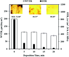
Barrier properties-WVTR and OTR. Resistance (barrier) to the permeation of gas and water vapor is a very important aspect from a packaging viewpoint. The barrier properties of ppTEOS deposited CSPCL films were studied by measuring the OTR and WVTR. Fig. 13 shows a decrease in the WVTR and OTR with increasing deposition time. With increasing deposition time, the barrier properties were found to improve. It was observed that a very thin layer (10 nm due to a 5 min deposition time) of ppTEOS deposited on CSPCL improves the oxygen barrier properties of the films by 80.12% and the water vapor barrier properties by 43.8%. This improvement in barrier properties was attributed to the highly cross-linked, conformal, pinhole free/dense, hydrophobic coating of ppTEOS on the CSPCL films.
image file: c5ra23414j-f13.tif
Fig. 13 The WVTR and OTR of CSPCL film and ppTEOS coated CSPCL films.

Biodegradation study

Degradation studies with indoor soil burial method. Studies conducted in conditions mimicking the natural environment using an indoor soil burial method on the samples provides a real picture of the degradation of the polymers in nature because of the similarity to onsite conditions of use and disposal. The microorganisms present in the soil use the polymer material as a source of carbon for their growth thereby degrading the polymer. Degradation of the polymer was indicated by alterations in its mechanical properties which included a loss in tensile strength (TS) and % elongation at break (Eb). The loss in TS (%) and loss in Eb (%) of samples not placed in soil (0 days) and placed in soil (7, 14, 28, 42 and 56 days) were calculated with respect to pristine (untreated and not placed in soil) CSPCL film and listed in Fig. 14.
image file: c5ra23414j-f14.tif
Fig. 14 Loss in TS (%) and loss in Eb (%) of untreated and TEOS-plasma deposited CSPCL films with indoor soil burial method.

It was observed that unburied TEOS-plasma deposited CSPCL films do not show a significant change in tensile properties but an overall reduction in the tensile properties of the untreated CSPCL polymer films was observed over burial time. The loss in tensile properties of ppTEOS deposited CSPCL films was in close comparison to that of untreated CSPCL films. Thus the presence of ppTEOS coating on CSPCL films did not adversely affect the biodegradability of the material. However, the mechanical properties represent the bulk properties of the material which may not be sensitive to the growth or colonization of micro-organisms. Therefore, it was thought interesting to study biodegradability using optical methods as well.

Fig. 15 shows OLM images (40×) of pristine and TEOS-plasma deposited CSPCL films placed in soil for 56 days. It can be seen that the TEOS-plasma deposited films (Fig. 15c and d) show reduced growth of soil flora compared to the untreated CSPCL film (Fig. 15b). This could be possible due to the presence of the hydrophobic and smooth nano structured ppTEOS coating.


image file: c5ra23414j-f15.tif
Fig. 15 OLM images (40×) of CSPCL films, (a) pristine (untreated & not placed in soil), and placed in soil for 56 days (b) untreated, and films with TEOS plasma deposited for (c) 10 min and (d) 20 min, placed in soil for 56 days.
Degradation studies with BS 121. A control (untreated) CSPCL film and ppTEOS deposited CSPCL films exposed to BS 121 for 56 days showed the lag, log, stationary and death phases of microorganisms used as indicated from turbidimetric studies (Fig. 16). It can be seen that the difference in turbidity between the untreated CSPCL and ppTEOS deposited CSPCL goes on increasing from 14 days onwards. The continuous increase in turbidity until 42 days in the case of the untreated CSPCL film indicates that the carbon source is available to the micro-organisms for growth. Whereas the ppTEOS films contain a SiOx layer i.e. less carbonaceous content, and hence a decrease in turbidity was observed in this case. The decrease in turbidity of the ppTEOS deposited films compared to the untreated CSPCL film indicates reduced growth of BS 121 suggesting a decrease in biodegradation. OLM images (Fig. 17) reveal changes in the visual appearance of surfaces exposed to BS 121 at day 7, day 14 and day 56, as compared to the pristine CSPCL film. These changes in visual appearance were attributed to alterations in the sample surfaces due to the colonization and adhesion of BS 121 on the sample surface. A decreasing trend in colonization and adhesion of BS 121 observed throughout the study was in agreement with the turbidimetric studies. The SEM images (Fig. 18) show the morphological changes in samples exposed to BS 121 for 56 days. It can be seen that the ppTEOS coated surfaces do not show significant morphological changes compared to untreated CSPCL films. The presence of a hydrophobic, smooth ppTEOS coating possibly limits the adhesion and growth of BS 121 which is in accordance with the turbidity results.
image file: c5ra23414j-f16.tif
Fig. 16 OD600 nm for untreated and TEOS-plasma deposited CSPCL exposed to BS 121 for 56 days.

image file: c5ra23414j-f17.tif
Fig. 17 OLM images (10×) of (a) pristine (untreated & not exposed to BS 121) CSPCL films, and TEOS plasma deposited (deposition time, 10 min) CSPCL films exposed to BS 121 for (b) 7 days, (c) 14 days and (d) 56 days.

image file: c5ra23414j-f18.tif
Fig. 18 SEM images of CSPCL samples exposed to BS 121 for 56 days (a) untreated and TEOS plasma deposited films with deposition times of (b) 10 min and (c) 20 min.

Conclusion

Out of many properties of silicon oxide coatings, the gas barrier properties are of great importance regarding packaging applications. Silicon oxide coated biodegradable polymers are one of the environmentally friendly solutions for increased packaging utilization. Plasma enhanced chemical vapor deposition of TEOS formed a nano (<100 nm), hydrophobic, highly cross-linked, pin-hole free/dense ppTEOS coating. FTIR, XPS and XRD studies revealed that the ppTEOS coating has a glass like structure along with inherent carbonaceous impurities. Morphological studies showed that the ppTEOS coating was smooth and conformal. A thin layer of ppTEOS coating (10 nm after 5 min deposition time) reduces the OTR and WVTR by 80.12% and 43.8% respectively. Biodegradation studies in an indoor soil environment showed no significant loss in tensile properties whereas OLM images showed reduced soil flora on ppTEOS coated CSPCL films with respect to the TEOS deposition time. In the case of bacterial degradation, with increasing TEOS deposition time, a slightly reduced growth of BS 121 on ppTEOS coated CSPCL was observed. Thus ppTEOS coated CSPCL films seem to be an attractive option for environmentally friendly packaging applications.

Acknowledgements

The author G. A. Arolkar wishes to acknowledge the University Grants Commission (UGC), India for the support provided through the UGC-SAP fellowship. The author Salgo M. Jacob also wishes to acknowledge UGC for the award of JRF.

References

  1. R. M. Marsh, Pap., Film Foil Converter, 1994, 2, 37–41 Search PubMed .
  2. A. L. Brody, Packag. Tech. Eng., 1994, 3, 44–50 Search PubMed .
  3. J. R. Hollahan and A. T. Bell, Techniques and Applications of Plasma Chemistry, John Wiley & Sons, New York, 1974 Search PubMed .
  4. Y. Segui and P. Raynaud, in Plasma Polymer Films, ed. H. Biederman, Imperial College Press, London, 2004, ch. 3, pp. 57–82 Search PubMed .
  5. M. A. Lieberman and A. J. Lichtenberg, in Principles of Plasma Discharges and Materials Processing, Wiley-Interscience, New York, 2nd edn, 2005, ch. 16, pp. 662–666 Search PubMed .
  6. W. Kulisch, T. Lippmann and R. Kassing, Thin Solid Films, 1989, 174, 57–61 CrossRef CAS .
  7. C. Vallee, A. Goullet, A. Granier, A. V. D. Lee, J. Durand and C. Marliere, J. Non-Cryst. Solids, 2000, 272, 163–173 CrossRef CAS .
  8. C. Voulgaris, E. Amanatides, D. Mataras, S. Grassini, E. Angelini and F. Rosalbino, Surf. Coat. Technol., 2006, 200, 6618–6622 CrossRef CAS .
  9. A. Mahdjoub, Semicond. Phys., Quantum Electron. Optoelectron., 2007, 10, 60–66 CAS .
  10. C.-H. Lo, W.-S. Hung, S.-H. Huang, M. D. Guzman, V. Rouessac, K.-R. Lee and J.-Y. Lai, J. Membr. Sci., 2009, 329, 138–145 CrossRef CAS .
  11. M. R. Holmes, L. Shuo, J. Keeley, M. Jenkins, K. Leake, H. Schmidt and A. R. Hawkins, IEEE Photonics Technol. Lett., 2011, 23, 1466–1468 CrossRef CAS .
  12. M. Abbasi-Firouzjah, S.-I. Hosseini, M. Shariat and B. Shokri, J. Non-Cryst. Solids, 2013, 368, 86–92 CrossRef CAS .
  13. H. Chatham, Surf. Coat. Technol., 1996, 78, 1–9 CrossRef CAS .
  14. A. G. Erlat, R. J. Spontak, R. P. Clarke, T. C. Robinson, P. D. Haaland, Y. Tropsha, N. G. Harvey and E. A. Vogler, J. Phys. Chem. B, 1999, 103, 6047–6055 CrossRef CAS .
  15. K. Johansson, Plasma Deposition of Barrier Coatings on Plastic Containers, Institute for Surface Chemistry (YKI) (Coord.), Swedish Institute for Food and Biotechn. (SIK), Swedish Packaging Research Institute (Packforsk), Nano Scale Surface Systems, Inc., (ns3), USA, Stockholm, 2000 Search PubMed .
  16. G. Czeremuszkin, M. Latreche, M. R. Wertheimer and A. S. d. S. Sobrinho, Plasmas Polym., 2001, 6, 107–120 CrossRef CAS .
  17. F. Welle and R. Franz, Food Addit. Contam., Part A, 2008, 25, 788–794 CrossRef CAS PubMed .
  18. S. Selke, Biodegradation and Packaging: A Literature Review, Pira International, 2nd edn, 1996 Search PubMed .
  19. J. Behnisch, J. Tyczkowski, M. Gaziski, I. Pela, A. Mollonder and R. Ledzion, Surf. Coat. Technol., 1998, 98, 872–874 CrossRef CAS .
  20. O. B. G. Assis and J. H. Hotchkiss, Packag. Technol. Sci., 2007, 20, 293–297 CrossRef CAS .
  21. F. Welle, presented in part at the 4th international Symposium on Food Packaging, Prague, 19-21 November 2008, p. 2008 Search PubMed .
  22. N. Tenn, N. Follain, K. Fatyeyeva, F. Poncin-Epaillard, C. Labrugere and S. Marais, RSC Adv., 2014, 4, 5626–5637 RSC .
  23. W. H. Koo, S. M. Jeong, S. H. Choi, W. J. Kim, H. K. Bail, S. M. Lee and S. J. Lee, J. Phys. Chem. B, 2005, 109, 11354–11360 CrossRef CAS PubMed .
  24. F. M. Fowkes, Ind. Eng. Chem., 1964, 56, 40–52 CrossRef CAS .
  25. D. K. Owens and R. C. Wendt, J. Appl. Polym. Sci., 1969, 13, 1741–1747 CrossRef CAS .
  26. D. H. Kaelble, J. Adhes., 1970, 2, 66–81 CrossRef CAS .
  27. W. Rabel, Farben, Lacke, Anstrichst., 1971, 77, 997–1005 CAS .
  28. R. R. Deshmukh and A. R. Shetty, J. Appl. Polym. Sci., 2008, 107, 3707–3717 CrossRef CAS .
  29. R. R. Deshmukh, G. A. Arolkar and S. S. Parab, Int. J. Chem. Phys. Sci., 2012, 1, 40–47 Search PubMed .
  30. R. R. Deshmukh and A. R. Shetty, J. Appl. Polym. Sci., 2007, 104, 449–457 CrossRef CAS .
  31. R. G. Lehmann, S. Varaprath, R. B. Annelin and J. L. Arndt, Environ. Toxicol. Chem., 1995, 14, 1299–1305 CrossRef CAS .
  32. R. G. Lehmann, J. R. Miller and H. P. Collins, Water, Air, Soil Pollut., 1998, 106, 111–122 CrossRef CAS .
  33. J. Lukasiak, A. Dorosz, M. Prokopowicz, P. Rosciszewski and B. Falkiewicz, in Biopolymers, Volume 9, Miscellaneous Biopolymers and Biodegradation of Synthetic Polymers, ed. S. Matsumura and A. Steinbüchel, Wiley-Blackwell, 2002, pp. 539–600 Search PubMed .
  34. R. P. Gandhiraman, M. K. Muniyappa, M. Dudek, C. Coyle, C. Volcke, A. J. Killard, P. Burham, S. Daniels, N. Barron, M. Clynes and D. C. Cameron, Plasma Processes Polym., 2010, 7, 411–421 CrossRef CAS .
  35. W. Song and J. F. Mano, Soft Matter, 2013, 9, 2985–2999 RSC .
  36. T.-J. Ko, E. Kim, S. Nagashima, K. H. Oh, K.-R. Lee, S. Kim and M.-W. Moon, Soft Matter, 2013, 9, 8705–8711 Search PubMed .
  37. J. Zhang, K. Kasuya, A. Takemura, A. Isogai and T. Iwata, Polym. Degrad. Stab., 2013, 98, 1458–1464 CrossRef CAS .
  38. G. A. Arolkar, M. J. Salgo, V. Kelkar-Mane and R. R. Deshmukh, Polym. Degrad. Stab., 2015, 120, 262–272 CrossRef CAS .
  39. H. Yasuda and T. Yasuda, J. Polym. Sci., Part A: Polym. Chem., 2000, 38, 943–953 CrossRef CAS .
  40. A. Neubecker, P. Bieringer, W. Hansch and I. Eisele, J. Cryst. Growth, 1995, 157, 201–206 CrossRef CAS .
  41. A. L. Smith, Spectrochim. Acta, 1960, 16, 87–105 CrossRef CAS .
  42. J. W. Ypenburg and H. Gerding, Recueil, 1972, 91, 1245–1274 CrossRef CAS .
  43. S. P. Mukherjee and P. E. Evans, Thin Solid Films, 1972, 14, 105–118 CrossRef CAS .
  44. N. Selamoglu, J. A. Mucha, D. E. Ibbotson and D. L. Flamm, J. Vac. Sci. Technol., B: Microelectron. Process. Phenom., 1989, 7, 1345–1351 CAS .
  45. K. H. A. Bogart, N. F. Dalleska, G. R. Bogart and E. R. Fisher, J. Vac. Sci. Technol., A, 1995, 13, 476–480 CAS .
  46. S. C. Deshmukh and E. S. Aydil, J. Vac. Sci. Technol., A, 1995, 13, 2355–2367 CAS .
  47. A. Grill and D. A. Neumayer, J. Appl. Phys., 2003, 94, 6697–6707 CrossRef CAS .
  48. K. Yamaoka, Y. Terai, Y. Yoshizako and Y. Fujiwara, Thin Solid Films, 2008, 517, 479–482 CrossRef CAS .
  49. R. M. Silverstein and F. X. Webster, in Spectrometric Identification of Organic Compounds, John Wiley & Sons, Inc., New York, 6th edn, 1998, ch. 3, p. 140 Search PubMed .
  50. G. Beamson and D. Briggs, High Resolution XPS of Organic Polymers, John Wiley & Sons, New York, 1992 Search PubMed .
  51. A. Goullet, C. Charles, P. Garcia and G. Turban, J. Appl. Phys., 1993, 74, 6876–6882 CrossRef CAS .
  52. Y. Yin, D. Liu, D. Li, J. Gu, Z. Feng, J. Niu, G. Benstetter and S. Zhang, Appl. Surf. Sci., 2009, 255, 7708–7712 CrossRef CAS .
  53. J. M. Lackner, C. Meindl, C. Wolf, A. Fian, C. Kittinger, M. Kot, L. Major, C. Czibula, C. Teichert, W. Waldhauser, A.-M. Weinberg and E. Fröhlich, Coatings, 2013, 3, 268–300 CrossRef .
  54. B. R. Manjunath, A. Venkataraman and T. Stephen, J. Appl. Polym. Sci., 1973, 17, 1091–1099 CrossRef CAS .
  55. N. V. Bhat and R. R. Deshmukh, Indian J. Pure Appl. Phys., 2002, 40, 361–366 CAS .
  56. V. Takke, N. Behary, A. Perwuelz and C. Campagne, J. Appl. Polym. Sci., 2009, 114, 348–357 CrossRef CAS .
  57. M. Gorenšek, M. Gorjanc and J. Kovac, Tekstilec, 2010, 53, 103–112 Search PubMed .
  58. M. Morra, E. Occhiello and F. Garbassi, J. Colloid Interface Sci., 1989, 132, 504–508 CrossRef CAS .
  59. F. Garbassi, M. Morra and E. Occhiello, Polymer Surfaces-From Physics to Technology, John Wiley & Sons, New York, 1998, pp. 317–349.
  60. A. M. Wrobel and M. R. Wertheimer, in Plasma Deposition, Treatment, and Etching of Polymers, ed. R. d’Agostino, Academic Press, New York, 1990, pp. 163–268 Search PubMed .

This journal is © The Royal Society of Chemistry 2016