One-pot synthesis of monodispersed porous CoFe2O4 nanospheres on graphene as an efficient electrocatalyst for oxygen reduction and evolution reactions†
Wenning Yana,
Xuecheng Caoa,
Ke Keb,
Jinghua Tiana,
Chao Jina and
Ruizhi Yang *a
*a
aCollege of Physics, Optoelectronics and Energy & Collaborative Innovation Center of Suzhou Nano Science and Technology, Soochow University, Suzhou 215006, China. E-mail: yangrz@suda.edu.cn; Tel: +86 512 65221519
bChilwee group, Changxing, Zhejiang 313100, China
First published on 16th December 2015
Abstract
Monodispersed porous spinel-type cobalt ferrite oxide (CoFe2O4) nanospheres (CFO-ns) directly grown on reduced graphene oxide (rGO) sheets are fabricated by a one-pot solvothermal method. With this special structure of CFO-ns and the covalent coupling between CFO-ns and rGO in the CFO-ns/rGO hybrid, more active sites are exposed and the transport of O2 and electrolyte is faciliated when the CFO-ns/rGO hybrid is employed as an electrocatalyst for the oxygen reduction reaction (ORR) and oxygen evolution reaction (OER). The CFO-ns/rGO hybrid demonstrates high catalytic activity for both the ORR and OER. It shows a more positive onset potential of −0.11 V (vs. Ag/AgCl) for the ORR, which is 50 mV higher than that of CFO-ns + rGO physical mixture (−0.16 V). Meanwhile, the onset potential of CFO-ns/rGO hybrid (0.56 V) for the OER is 40 mV lower than that of CFO-ns + rGO mixture (0.60 V). The high activity of the CFO-ns/rGO hybrid is attributed to the special structure of CFO-ns, the covalent coupling between CFO-ns and rGO as well as the suppressed agglomeration of CFO-ns and restacking of rGO in the hybrid. Moreover, the covalent coupling between CFO-ns and rGO endows the hybrid with excellent electrochemical stabilities for both the ORR and OER.
1. Introduction
The sluggish kinetics of the oxygen reduction reaction (ORR) and oxygen evolution reaction (OER) at the oxygen electrode are the main challenges that limit the practical use of rechargeable metal–air batteries.1–5 In order to maximize the electricity generated by metal–air batteries, electrocatalysts are used to promote the ORR and OER. Platinum-based materials are well known to be the most efficient electrocatalysts for the ORR.6–9 RuO2 and IrO2 have been regarded as the most promising electrocatalysts for OER.10–12 However, Pt, RuO2 and IrO2 all suffer from high cost and scarcity. Furthermore, their durability still needs to be improved due to the dissolution and subsequent agglomeration of nanoparticles during the long-term operation of metal–air batteries.To reduce the cost of electrocatalysts, research efforts have been mainly focused on the development of first row transition metal based electrocatalysts instead of precious metal based electrocatalysts for the ORR and OER. Spinel-type transition metal oxides, with transition metals having multiple valence state, such as Co3O4,13,14 CoMn2O4/MnCo2O4,15–17 CuxCo3−xO4![[thin space (1/6-em)]](https://www.rsc.org/images/entities/char_2009.gif) 18 and NiCo2O4,19–21 have been reported to show considerable electrocatalytic activities for both the ORR and OER in alkaline solution. However, cobalt ferrite oxide (CoxFe3−xO4 (1 ≤ x ≤ 2)) as a bi-functional electrocatalyst for ORR and OER is still rarely reported.
18 and NiCo2O4,19–21 have been reported to show considerable electrocatalytic activities for both the ORR and OER in alkaline solution. However, cobalt ferrite oxide (CoxFe3−xO4 (1 ≤ x ≤ 2)) as a bi-functional electrocatalyst for ORR and OER is still rarely reported.
It's known that the electrocatalytic activity of spinel oxides is limited by their low electrical conductivity.1 Moreover, the adsorption and dissociation of oxygen molecules during the ORR and OER processes mainly occur at the surface/interface of catalysts,21,22 so a rational design of nanostructure with a relatively high specific surface area is essential for further activity improvement of the electrocatalysts. Generally, growing or supporting the spinel nanoparticles on carbon based materials is an effective approach to improve the electrical conductivity.22,23 Recent reports have shown various spinel oxide electrocatalysts supported on different carbon materials, such as MnxCo3−xO4/graphene,15,17,24 NixCo3−xO4/graphene25,26 and Co3O4/MWCNT.27,28 For the design of nanostructure of spinel oxide, the special structures assembled with hollow spheres,29 concave nanocubes30 and nanowires31,32 have been reported. These special geometric structures with high specific surface area are beneficial for the efficient transport of electrolyte and oxygen molecules during the ORR and OER processes.19,28 Two-dimensional graphene possesses high electronic conductivity, large specific surface area and high chemical stability, which make it an excellent support for electrocatalysts.33,34 However, it suffers from the serious agglomeration and restacking of neighboring graphene sheets due to van der Waals interactions,35 which limits the activities of graphene based materials for ORR and OER.35,36
In this study, special structured porous CFO nanospheres (CFO-ns) supported on graphene sheets were successfully fabricated by a one-pot solvothermal approach. The CFO nanospheres distributed uniformly on both sides of graphene layers prevent the graphene sheets from restacking. Meanwhile, the special structured CFO nanospheres are assembled with nanoparticles, the voids between the nanoparticles facilitate the mass transport of O2 and electrolyte at the triple-phase (solid–liquid–gas) region. Moreover, the covalent bonding between CFO and graphene not only impedes the detachment of nanoparticles from graphene but also ensures a fast electron transport. The as-obtained CFO-ns/rGO exhibits much enhanced electrocatalytic activity and durability for both the ORR and OER in alkaline media as compared with the physical mixture of CFO-ns and rGO.
2. Experimental
2.1 Synthesis of samples
The CFO nanospheres/reduced graphene oxide hybrid (CFO-ns/rGO) was prepared by a one-pot solvothermal method. Graphene oxide (GO) was prepared by a modified Hummers' method through the oxidation of natural flack graphite as described elsewhere.37,38 For the synthesis of CFO-ns/rGO, 75 mg of graphene oxide was firstly dispersed in 60 mL of ethylene glycol (EG) and ultrasonicated for 2 h to achieve a homogeneous suspension. Subsequently, 2.08 g of Fe(NO3)3·9H2O and 0.75 g of Co(NO3)2·6H2O were dissolved in the above suspension and stirred for 20 min. After a complete dissolution, 6.0 g of urea and 0.76 g of poly(vinyl pyrrolidone) (PVP, Mw = 58![[thin space (1/6-em)]](https://www.rsc.org/images/entities/char_2009.gif) 000) were added to the suspension slowly, followed by a continuous stirring for 2 h at ambient temperature. After that, the resulting suspension was transferred into a 100 mL Teflon-lined autoclave, sealed and reacted at 200 °C for 20 h, then cooled to ambient temperature naturally. Finally, the black precipitate (i.e. CFO-ns/rGO) was collected by centrifugation, washed with ethanol and deionized water for several times and dried by lyophilization. The pure CFO nanospheres (CFO-ns), rGO and hybrid (CFO(rGO)) without nitrogen doping were also synthesized for comparison by using the same procedure but without the introduction of graphene oxide, metal ions or urea.
000) were added to the suspension slowly, followed by a continuous stirring for 2 h at ambient temperature. After that, the resulting suspension was transferred into a 100 mL Teflon-lined autoclave, sealed and reacted at 200 °C for 20 h, then cooled to ambient temperature naturally. Finally, the black precipitate (i.e. CFO-ns/rGO) was collected by centrifugation, washed with ethanol and deionized water for several times and dried by lyophilization. The pure CFO nanospheres (CFO-ns), rGO and hybrid (CFO(rGO)) without nitrogen doping were also synthesized for comparison by using the same procedure but without the introduction of graphene oxide, metal ions or urea.
2.2 Physical characterization
The crystallographic structure of the as-prepared samples were characterized by powder X-ray diffraction (XRD, Bede D1 X-ray diffractometer, Cu Kα radiation, λ = 1.5418 Å) with 2θ ranging from 10° to 80° at a scanning rate of 1° min−1.The morphology and microstructure of the products were investigated by scanning electron microscopy (SEM, SU8010, 10 kV) and transmission electron microscopy (TEM, TecnaiG220, 200 kV).
X-ray photoelectron spectroscopy (XPS, VG ESCALAB MKII) was carried out to analyze the element binding environment of the samples.
Thermogravimetric (TG, PerkinElmer TGA7, air: 40–800 °C, heating rate: 10 °C min−1) analysis was used to determine the amount of CFO in CFO-ns/rGO hybrid.
The content of metal ions in the prepared CFO-ns/rGO was investigated by the inductively coupled plasma emission spectrometer (ICP, Optima 8000).
2.3 Electrochemical measurements
Inks of the catalyst samples were prepared by mixing 5 mg of active materials (CFO-ns and CFO-ns/rGO) with 95 μL of Nafion solution (5 wt%) and 350 μL of ethanol, followed by ultrasonication for 30 min to form a homogeneous ink. In the CFO-ns case, 5 mg of acetylene black (AB) were added. Afterwards, 7 μL of the catalyst ink was dropped onto a glassy carbon electrode with a diameter of 5 mm, generating a catalyst film. The loading of the catalyst is 401 μg cm−2. The ink of Pt/C (20 wt%, Johnson Matthey) and RuO2/C (20 wt%) catalyst were prepared by the same procedure.The rotating ring-disk electrode (RRDE) in Pine electrochemical system (AFMSRX rotator, and AFCBP1 bipotentiostat) was used to evaluate the electrocatalytic activities of the samples for ORR and OER. The RRDE electrode is composed of a catalyst-coated glassy carbon disk (5 mm diameter, 0.196 cm2 of geometric surface area) surrounded by a Pt ring (0.125 cm2 of geometric surface area). The electrochemical measurements were carried out in a standard three-electrode electrochemical cell configuration using the 0.1 M KOH solution as electrolyte. The Ag/AgCl (3 M Cl−, Cypress) electrode and Pt-foil were used as the reference and counter electrode, respectively. The linear sweep voltammetry (LSV) for the ORR on samples was recorded from −0.80 to 0 V at a scanning rate of 10 mV s−1 with the electrode rotated at 400, 900, 1600 and 2500 rpm in O2-saturated 0.1 M KOH electrolyte. The LSV for the OER on samples was recorded from 0.1 to 0.9 V at a scanning rate of 10 mV s−1 with the electrode rotated at 1600 rpm in a N2-saturated 0.1 M KOH electrolyte to spin off the oxygen evolved during testing.
3. Results and discussion
3.1 Synthesis and characterization of the catalysts
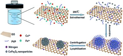
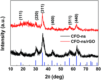
The preparation of CFO-ns/rGO hybrid is shown in Scheme 1. When Fe(NO3)3·9H2O and Co(NO3)2·6H2O were added to the ethylene glycol solution of graphene oxide (GO). The Co2+ and Fe3+ cations were electrostatically attracted by negatively charged GO. As the temperature increased, the urea was hydrolyzed into ammonia and carbon dioxide to provide an alkaline environment for the formation of Fe(OH)3 and Co(OH)2 as intermediates during the solvothermal process.39 The hydroxides are then dehydrated to form CoFe2O4 (CFO) nanoparticles. The particle size of CFO was restricted with the PVP capping agent. As the time goes on, the CFO nanoparticles were assembled into hierarchically porous CFO nanospheres on graphene due to the attractive magnetic forces and their instinctive nature to reduce the surface energy by aggregation.40,41 The chemisorption of PVP ligand on the surface prevents the CFO nanospheres from further growth/aggregation, which makes the size of nanospheres controllable.42 The capping effect of PVP is also confirmed by the sample prepared without the addition of PVP, which presents a dense clump morphology (Fig. S1a, ESI†).Fig. 1 shows the XRD patterns of the CFO-ns and CFO-ns/rGO. All diffraction peaks in both samples can be indexed to cubic spinel-type CoFe2O4 (PDF#22-1086) with no other recognizable diffraction peaks observed, indicating high purity of the as-synthesized samples. The diffraction peaks for graphene in CFO-ns/rGO cannot be distinguished, which suggests that the CFO nanospheres are deposited on both sides of the graphene, suppressing the stacking of graphene layers.36 The crystallite size of CFO in CFO-ns/rGO is calculated to be ∼8.7 nm from the (311) peak by Scherrer formula.41 The mass fraction of CFO nanospheres in the CFO-ns/rGO hybrid is obtained from the thermogravimetric analysis (TGA) profile as shown in Fig. S2a.† The slight dropping of the weight (∼0.6 wt%) below 100 °C can be ascribed to the evaporation of water. The graphene in CFO-ns/rGO begin to decompose markedly at about 190 °C and burn thoroughly by 400 °C. The final weight ratio of CFO in CFO-ns/rGO hybrid is measured to be ∼86.5 wt%, revealing a high loading of CFO nanospheres on graphene. The specific surface area and pore size distribution of the as-prepared CFO-ns/rGO hybrid are characterized by the nitrogen adsorption–desorption measurements (Fig. S2b, ESI†). The isotherm of CFO-ns/rGO hybrid shows a type IV isotherm with a H1 hysteresis loop. The CFO-ns/rGO hybrid possesses a BET specific surface area of 34.84 m2 g−1 and pore volume of 0.138 cm3 g−1, indicating the porous structure of the hybrid. This value is much lower than that of the as-prepared graphene sheets (246.73 m2 g−1) due to the high loading of CFO nanospheres on graphene. The pore size distribution of the hybrid is in the range of 2–10 nm, which mainly results from the voids between the nanoparticles assembled in the nanospheres and from the pores in the reduced graphene oxide sheets.
The scanning electron microscopy (SEM) and transmission electron microscopy (TEM) were employed to investigate the morphology and microstructure of the as-prepared samples (Fig. 2). It can be observed from Fig. 2a and b that the CFO nanospheres with an average size of ∼70 nm are uniformly and monodispersely distributed on both sides of the graphene sheets in the CFO-ns/rGO hybrid. A close inspection of high-magnification TEM image of the individual CFO nanospheres (Fig. 2c) supported on graphene shows that these nanospheres are composed of orderly assembled nanoparticles with diameters ranging from 3 to 10 nm, which is in good agreement with the value obtained from the XRD pattern (Fig. 1). The voids between adjacent nanoparticles give rise to the porosity. Note that the CFO nanospheres without support show similar morphology and an average size of ∼70 nm (Fig. S1b–d, ESI†). The high-resolution TEM (HRTEM) image of CFO-ns/rGO (Fig. 2d) shows the lattice fringes with a lattice spacing of 0.485 nm and 0.297 nm, corresponding to the (111) and (220) planes of CoFe2O4, respectively. The atomic ratio of Co![[thin space (1/6-em)]](https://www.rsc.org/images/entities/char_2009.gif) :
:![[thin space (1/6-em)]](https://www.rsc.org/images/entities/char_2009.gif) Fe in CFO-ns/rGO is close to 1
Fe in CFO-ns/rGO is close to 1![[thin space (1/6-em)]](https://www.rsc.org/images/entities/char_2009.gif) :
:![[thin space (1/6-em)]](https://www.rsc.org/images/entities/char_2009.gif) 2 as determined by the ICP measurement (Table S1 ESI†), further confirming the formation of CoFe2O4 in CFO-ns/rGO hybrid.
2 as determined by the ICP measurement (Table S1 ESI†), further confirming the formation of CoFe2O4 in CFO-ns/rGO hybrid.
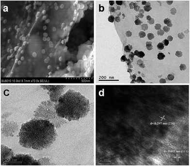 | ||
| Fig. 2 (a) SEM image of CFO-ns/rGO hybrid. (b) and (c) TEM images of CFO-ns/rGO hybrid. (d) HRTEM image of CFO-ns/rGO hybrid. | ||
The surface composition and chemical environment of elements in CFO-ns and CFO-ns/rGO hybrid were studied by X-ray photoelectron spectroscopy (XPS). The survey scan shows the existence of C, O, N, Fe and Co in CFO-ns/rGO (Fig. 3a). High resolution XPS spectrum of O 1s in CFO-ns (Fig. 3b) can be deconvoluted into three recognizable components centered at 530.0, 531.5 and 533.0 eV, which are associated with metal–oxygen bond (M–O–M), the surface adsorbed hydroxyl groups species (M–O–H), and the oxygen in surface-adsorbed carbonate anions, respectively.43–45 Moreover, the asymmetric peak emerged at 529.0 eV in the CFO-ns/rGO hybrid can be assigned to the metal–oxygen–carbon bond (M–O–C), suggesting the covalent coupling between CFO-ns and rGO. In addition, the incorporation of N in the rGO is confirmed by the N 1s spectra (Fig. S3, ESI†) and ∼4.5 atom% of N is measured to be present in the hybrid. Two forms of nitrogen configuration, namely pyridinic N (398.3 eV, 79.5%) and pyrrolic N (400.1 eV, 20.5%) can be identified.36,46
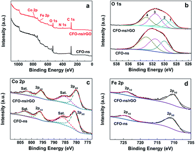 | ||
| Fig. 3 (a) XPS survey spectra of CFO-ns and CFO-ns/rGO. (b), (c) and (d) High-resolution XPS spectras of O 1s, Co 2p and Fe 2p for CFO-ns and CFO-ns/rGO. | ||
The Co 2p spectrum for pristine CFO-ns (Fig. 3c) is composed of two main peaks at 796.3 and 780.7 eV with a spin–orbit splitting of ∼15.6 eV, which can be identified as Co 2p1/2 and Co 2p3/2. There are also two shakeup satellites at 802.8 eV and 785.8 eV. All these peaks indicate the presence of high spin state of Co2+ in the sample.22,47 It is worth noting that a shift of ∼0.7 eV for Co 2p3/2 and ∼0.5 eV for Co 2p1/2 towards lower binding energy, respectively, are observed for CFO-ns/rGO as compared with CFO-ns. The spectrum of Fe 2p exhibits two peaks located at around 710.9 and 724.3 eV (Fig. 3d), corresponding to Fe 2p3/2 and Fe 2p1/2, respectively, which indicates the existence of Fe3+.22,48 Similarly, there is a negative shift of ∼0.6 eV and ∼0.3 eV for Fe 2p3/2 and Fe 2p1/2, respectively, in CFO-ns/rGO as compared with CFO-ns. The negative shifts in the binding energy of Co and Fe further confirm the existence of covalent coupling between CFO-ns and rGO in the CFO-ns/rGO hybrid.
3.2 Electrocatalytic activity of the catalysts
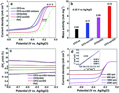
The ORR electrocatalytic activity of the CFO-ns/rGO hybrid was evaluated using a rotating-ring disk electrode (RRDE) in O2-saturated 0.1 M KOH solution. Fig. 4a compares the polarization curves of CFO-ns, CFO-ns + rGO mixture, CFO(rGO), CFO-ns/rGO and commercial Pt/C (20 wt%, Johnson Matthey) for ORR at a rotation rate of 1600 rpm. The CFO-ns/rGO hybrid shows an onset potential of −0.11 V and a diffusion limiting current density of −5.51 mA cm−2, which are superior to those of CFO-ns (onset potential: −0.17 V, diffusion limiting current density: −4.87 mA cm−2), CFO-ns + rGO mixture (onset potential: −0.16 V, diffusion limiting current density: −5.07 mA cm−2) and CFO(rGO) (onset potential: −0.14 V, diffusion limiting current density: −4.88 mA cm−2). The ORR activity of CFO-ns/rGO is comparable to that of Pt/C (onset potential: −0.01 V, diffusion limiting current density: −5.88 mA cm−2), a negative shift of about 81 mV existing in the half-wave potential of CFO-ns/rGO as compared to that of Pt/C. Furthermore, the mass activities of the samples in the mixed kinetic-diffusion controlled region are calculated. The mass activity of CFO-ns/rGO (8.73 mA mg−1) at the potential of −0.25 V (Fig. 4b) is 3.6, 2.1 and 1.6 times that of CFO-ns, CFO-ns + rGO mixture and CFO(rGO), respectively, further indicating the high activity of the hybrid toward ORR.The peroxide species (HO2−) and electron number (n) transferred during ORR process were monitored with RRDE measurements. As shown in Fig. 4c, the measured HO2− yields are 9.20–14.05% and 8.10–12.63% for CFO-ns + rGO mixture and CFO(rGO) over the potential range of −0.80 to −0.30 V. It decreases to 1.91–3.22% for CFO-ns/rGO hybrid, giving an electron transfer number of 3.94–3.96, very close to that of Pt/C (3.92–3.95), revealing a desirable 4e− oxygen reduction pathway. These results suggest that growing CFO-ns on rGO also modify the ORR catalytic pathway as compared with the physical mixture of CFO-ns and rGO (i.e. CFO-ns + rGO).
Fig. 4d shows the polarization curves of ORR on CFO-ns/rGO at different rotation speeds, all of them reach diffusion limiting currents. The ORR pathway of CFO-ns/rGO hybrid was further examined according to the Koutecky–Levich equation:22,30
 | (1) |
![[thin space (1/6-em)]](https://www.rsc.org/images/entities/char_2009.gif) 485 C mol−1), DO2 and CO2 are the oxygen diffusion coefficient and oxygen concentration dissolved in 0.1 M KOH, respectively, ω is the electrode rotation rate, and ν is the kinetic viscosity of the electrolyte. The average electron number calculated from the slope of parallel lines over the potential range from −0.35 to −0.60 V is about 4.0 (inset in Fig. 4d), which is consistent with the RRDE measurements.
485 C mol−1), DO2 and CO2 are the oxygen diffusion coefficient and oxygen concentration dissolved in 0.1 M KOH, respectively, ω is the electrode rotation rate, and ν is the kinetic viscosity of the electrolyte. The average electron number calculated from the slope of parallel lines over the potential range from −0.35 to −0.60 V is about 4.0 (inset in Fig. 4d), which is consistent with the RRDE measurements.
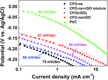
The Tafel plots of ORR on CFO-ns/rGO (Fig. 5) are constructed using the kinetic currents derived from eqn (1). At low over-potentials, the slope fitted from the linear region is 61 mV dec−1 for CFO-ns/rGO hybrid, approaching the theoretical value of 2.303 RT/F (∼59 mV dec−1 at 25 °C), where R, T and F are the universal gas constant, the Faraday constant and the absolute temperature, respectively. The Tafel slope for CFO-ns/rGO hybrid is lower than that for CFO-ns (78 mV dec−1), CFO-ns + rGO mixture (68 mV dec−1), CFO(rGO) (65 mV dec−1) and commercial Pt/C (66 mV dec−1), suggesting a high intrinsic catalytic activity and an enhanced ORR kinetics.22
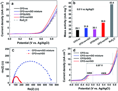
The electrocatalystic activity of CFO-ns/rGO for OER is evaluated in N2-saturated 0.1 M KOH at 1600 rpm as shown in Fig. 6a. As compared with CFO-ns, CFO-ns + rGO mixture and CFO(rGO), the OER activity of CFO-ns/rGO is enhanced as evidenced by the lower onset potential (0.56 V) and higher current density (23.9 mA cm−2 at 0.9 V). The onset potential of CFO-ns/rGO is very close to that of RuO2/C (20 wt%, 0.55 V) and its current density at 0.9 V is even higher than that of the latter (17.0 mA cm−2). From Fig. 6b, it's also clear that the mass activity of CFO-ns/rGO is superior to that of CFO-ns and CFO-ns + rGO mixture, respectively. More importantly, CFO-ns/rGO affords a much lower charge transfer impedance as revealed by the smaller semicircular diameter in the electrochemical impedance spectrum (Fig. 6c) as compared with the CFO-ns + rGO mixture, indicating a more efficient charge transfer in the hybrid.49,50 Besides, more active sites are exposed and transport of O2 and electrolyte are faciliated due to the special structured CFO-ns and uniform distribution of monodispersed CFO-ns on both sides of the graphene sheets, which are beneficial for the OER process. All these facts above result in the enhanced OER activity of CFO-ns/rGO. As displayed in Fig. 6d, the difference between the half wave potential at an ORR current density of 3 mA cm−2 and the potential at an OER current density of 10 mA cm−2 are used to assess the overall oxygen electrode activity using the solar to fuel device conversion scale.51,52 The value (ΔE = EOER − EORR) for CFO-ns/rGO is 0.97 V, which is much lower than that of CFO-ns (1.12 V), CFO-ns + rGO mixture (1.06 V) and CFO(rGO) (1.03 V), indicating an improved bifunctional electrocatalytic activity due to the anchoring of CFO-ns on rGO through a covalent bonding. These results indicate that the CFO-ns/rGO hybrid is an efficient bi-functional electrocatalyst for ORR and OER.
The enhanced catalytic activity of CFO-ns/rGO for the ORR and OER can be attributed to the following factors. Firstly, the interfacial covalent M–O–C between CFO-ns and rGO provides pathways for charge transport from rGO to CFO-ns, increasing the electronic conductivity of CFO, which is poor as reported in previous works.53,54 This covalent M–O–C also tailors the electronic state of the redox couples and reduces the electron cloud density around Co/Fe, facilitating the ORR and OER processes.53 Secondly, the special structure of CFO-ns, together with suppressed agglomeration of CFO-ns and restacking of rGO in the hybrid due to the uniform distribution of CFO-ns on both sides of graphene sheets, exposes more active sites and favors the transport of O2 and electrolyte as confirmed from the EIS measurements (Fig. 6c). In addition, the N-doping (mainly pyridinic N, Fig. S3†) in rGO benefits the ORR,4 which is also evidenced by the higher activities of CFO-ns/rGO toward ORR and OER compared with that of CFO(rGO).
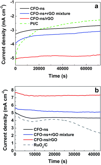
Besides the considerable electrocatalytic activity, the CFO-ns/rGO hybrid also affords remarkable stabilities for both ORR and OER, which were evaluated via a chronoamperometric method in O2- and N2-saturated 0.1 M KOH solution, respectively. As given in Fig. 7a, the CFO-ns/rGO hybrid shows a decrease of only 6% in ORR current density after 72![[thin space (1/6-em)]](https://www.rsc.org/images/entities/char_2009.gif) 000 s of continuous operation at −0.35 V. While a much higher decrease of 18.5% and 21.3% in ORR current densities are observed for CFO-ns and CFO-ns + rGO mixture, respectively. Although the commercial Pt/C is catalytically active for ORR, it exhibits a severe degradation of 58.9%. The CFO-ns/rGO also shows excellent stability for OER and maintained 94.5% of its original current density over 43200 s of continuous operation at 0.7 V (Fig. 7b). In contrast, the CFO-ns, CFO-ns + rGO mixture and RuO2/C attain a retention of 85.4%, 90.2% and 45.7% in current densities, respectively. The improved electrochemical stabilities of CFO-ns/rGO for both ORR and OER result from the covalent coupling between CFO-ns and rGO in the hybrid, which mitigates the particulate agglomeration of CFO-ns and detachment of them from the graphene.55,56
000 s of continuous operation at −0.35 V. While a much higher decrease of 18.5% and 21.3% in ORR current densities are observed for CFO-ns and CFO-ns + rGO mixture, respectively. Although the commercial Pt/C is catalytically active for ORR, it exhibits a severe degradation of 58.9%. The CFO-ns/rGO also shows excellent stability for OER and maintained 94.5% of its original current density over 43200 s of continuous operation at 0.7 V (Fig. 7b). In contrast, the CFO-ns, CFO-ns + rGO mixture and RuO2/C attain a retention of 85.4%, 90.2% and 45.7% in current densities, respectively. The improved electrochemical stabilities of CFO-ns/rGO for both ORR and OER result from the covalent coupling between CFO-ns and rGO in the hybrid, which mitigates the particulate agglomeration of CFO-ns and detachment of them from the graphene.55,56
4. Conclusions
In summary, porous CFO nanospheres (CFO-ns) growing on graphene (CFO-ns/rGO) was successfully fabricated via a one-pot solvothermal approach. The CFO-ns are assembled with nanoparticles and distributed uniformly on both sides of the graphene sheets. Benefiting from the special structure of CFO-ns, the suppressed agglomeration of CFO-ns and restacking of rGO as well as the strong coupling between CFO-ns and rGO, the resulting CFO-ns/rGO hybrid has demonstrated a high catalytic activity for ORR and OER in alkaline solution. The results indicate that CFO-ns/rGO hybrid is a promising bifunctional catalyst for both ORR and OER.Acknowledgements
This work is supported by National Natural Science Foundation of China (No. 51272167, 21206101 and 51572181) and Natural Science Foundation of Jiangsu Province, China (BK20151226).Notes and references
- L. F. Wu, H. B. Feng, M. J. Liu, K. X. Zhang and J. H. Li, Nanoscale, 2013, 5, 10839 RSC
.
- J. Du, Y. D. Pan, T. R. Zhang, X. P. Han, F. Y. Cheng and J. Chen, J. Mater. Chem., 2012, 22, 15812 RSC
.
- X. M. Ren, S. S. Zhang, D. T. Tran and J. Read, J. Mater. Chem., 2011, 21, 10118 RSC
.
- Y. Y. Liang, Y. G. Li, H. L. Wang, J. G. Zhou, J. Wang, T. Regier and H. J. Dai, Nat. Mater., 2011, 10, 780 CrossRef CAS PubMed
.
- A. A. Gewirth and M. S. Thorum, Inorg. Chem., 2010, 49, 3557 CrossRef CAS PubMed
.
- J. Wu, Z. R. Yang, X. W. Li, Q. J. Sun, C. Jin, P. Strasser and R. Z. Yang, J. Mater. Chem. A, 2013, 1, 9889 CAS
.
- S. Zhang, Y. Y. Shao, G. P. Yin and Y. H. Lin, J. Mater. Chem., 2010, 20, 2826 RSC
.
- C. Galeano, J. C. Meier, V. Peinecke, H. Bongard, I. Katsounaros, A. A. Topalov, A. H. Lu, K. J. J. Mayrhofer and F. Schuth, J. Am. Chem. Soc., 2012, 134, 20457 CrossRef CAS PubMed
.
- M. H. Shao, G. N. He, A. Peles, J. H. Odella, J. Zeng, D. Su, J. Tao, T. K. Yu, Y. M. Zhu and Y. N. Xia, Chem. Commun., 2013, 49, 9030 RSC
.
- M. G. Walter, E. L. Warren, J. R. McKone, S. W. Boettcher, Q. Mi, E. A. Santori and N. S. Lewis, Chem. Rev., 2010, 110, 6446 CrossRef CAS PubMed
.
- Y. Lee, J. Suntivich, K. J. May, E. E. Perry and Y. Shao-Horn, J. Phys. Chem. Lett., 2012, 3, 399 CrossRef CAS PubMed
.
- T. Y. Ma, S. Dai, M. Jaroniec and S. Z. Qiao, J. Am. Chem. Soc., 2014, 136, 13925 CrossRef CAS PubMed
.
- M. Hamdani, R. N. Singh and P. Chartier, Int. J. Electrochem. Sci., 2010, 5, 556 CAS
.
- J. A. Koza, Z. He, A. S. Miller and J. A. Switzer, Chem. Mater., 2012, 24, 3567 CrossRef CAS
.
- L. Wang, X. Zhao, Y. Lu, M. Xu, D. Zhang, R. S. Ruoff, K. J. Stevenson and J. B. Goodenough, J. Electrochem. Soc., 2011, 158, 1379 CrossRef
.
- F. Y. Cheng, J. Shen, W. Q. Ji, Z. L. Tao and J. Chen, ACS Appl. Mater. Interfaces, 2009, 1, 460 CAS
.
- H. L. Wang, Y. Yang, Y. Y. Liang, G. Y. Zheng, Y. G. Li, Y. Cui and H. J. Dai, Energy Environ. Sci., 2012, 5, 7931 CAS
.
- M. D. Koninck, S. C. Poirier and B. Marsan, J. Electrochem. Soc., 2007, 154, 381 CrossRef
.
- L. X. Zhang, S. L. Zhang, K. J. Zhang, G. J. Xu, X. He, S. M. Dong, Z. H. Liu, C. S. Huang, L. Guo and G. L. Cui, Chem. Commun., 2013, 49, 3540 RSC
.
- B. Sun, J. Q. Zhang, P. Munroe, H. J. Ahn and G. X. Wang, Electrochem. Commun., 2013, 31, 88 CrossRef CAS
.
- J. Wu, C. Jin, Z. R. Yang, J. H. Tian and R. Z. Yang, Carbon, 2015, 82, 562 CrossRef CAS
.
- Y. J. Wang, D. P. Wilkinson and J. Zhang, Chem. Rev., 2011, 111, 7625 CrossRef CAS PubMed
.
- Y. J. Yao, Z. H. Yang, D. W. Zhang, W. C. Peng, H. Q. Sun and S. B. Wang, Ind. Eng. Chem. Res., 2012, 51, 6044 CrossRef CAS
.
- S. B. Yang, X. L. Feng, S. Ivanovici and K. Mullen, Angew. Chem., Int. Ed., 2010, 49, 8408 CrossRef CAS PubMed
.
- R. J. Zou, K. B. Xu, T. Wang, G. J. He, Q. Liu, X. J. Liu, Z. Y. Zhang and J. Q. Hu, J. Mater. Chem. A, 2013, 1, 8560 CAS
.
- D. U. Lee, B. J. Kim and Z. W. Chen, J. Mater. Chem. A, 2013, 1, 4754 CAS
.
- Y. Y. Liang, Y. G. Li, H. L. Wang and H. J. Dai, J. Am. Chem. Soc., 2013, 135, 2013 CrossRef CAS PubMed
.
- Y. Y. Liang, H. D. Wang, P. Diao, W. Chang, G. S. Hong, Y. G. Li, M. Gong, L. M. Xie, J. G. Zhou, J. Wang, T. Z. Regier, F. Wei and H. J. Dai, J. Am. Chem. Soc., 2012, 134, 15849 CrossRef CAS PubMed
.
- M. Fu, Q. Z. Jiao, Y. Zhao and H. S. Li, J. Mater. Chem. A, 2014, 2, 735 CAS
.
- Y. Y. Lu, W. W. Zhan, Y. He, Y. T. Wang, X. J. Kong, Q. Kuang, Z. X. Xie and L. S. Zheng, ACS Appl. Mater. Interfaces, 2014, 6, 4186 CAS
.
- Y. N. Xu, X. F. Wang, C. H. An, Y. J. Wang, L. F. Jiao and H. T. Yuan, J. Mater. Chem. A, 2014, 2, 16480 CAS
.
- S. G. Mohamed, T. F. Hung, C. J. Chen, C. K. Chen, S. F. Hu and R. S. Liu, RSC Adv., 2014, 4, 17230 RSC
.
- J. W. Sun, Y. S. Fu, P. Xiong, X. Q. Sun, B. H. Xu and X. Wang, RSC Adv., 2013, 3, 22490 RSC
.
- Y. B. Zhang, Y. W. Tan, H. L. Stormer and P. Kim, Nature, 2005, 438, 201 CrossRef CAS PubMed
.
- Y. Wang, Z. Q. Shi, Y. Huang, Y. F. Ma, C. Y. Wang, M. M. Chen and Y. S. Chen, J. Phys. Chem. C, 2009, 113, 13103 CAS
.
- Z. S. Wu, S. B. Yang, Y. Sun, K. Parvez, X. L. Feng and L. Mullen, J. Am. Chem. Soc., 2012, 134, 9082 CrossRef CAS PubMed
.
- J. Chen, B. W. Yao, C. Li and G. Q. Shi, Carbon, 2013, 64, 225 CrossRef CAS
.
- D. C. Marcano, D. V. Kosynkin and J. M. Berlin, ACS Nano, 2010, 4, 4806 CrossRef CAS PubMed
.
- D. Y. Chen, G. Ji, Y. Ma, J. Y. Lee and J. M. Lu, ACS Appl. Mater. Interfaces, 2011, 3, 3078 CAS
.
- S. B. Ni, X. L. Sun, X. H. Wang, G. Zhou, F. Yang, J. M. Wang and D. Y. He, Mater. Chem. Phys., 2010, 124, 353 CrossRef CAS
.
- R. L. Ji, C. B. Cao, Z. Chen, H. Z. Zhai and J. Bai, J. Mater. Chem. C, 2014, 2, 5944 RSC
.
- J. Y. Xian, Q. Hua, Z. Q. Jiang, Y. S. Ma and W. X. Huang, Langmuir, 2012, 28, 6736 CrossRef CAS PubMed
.
- J. F. Li, S. L. Xiong, X. W. Li and Y. T. Qian, J. Mater. Chem., 2012, 22, 23254 RSC
.
- R. Ding, L. L. Lv, L. Qi, M. J. Jia and H. Y. Wang, RSC Adv., 2014, 4, 1754 RSC
.
- S. L. Xiong, J. S. Chen, X. W. Lou and H. C. Zeng, Adv. Funct. Mater., 2012, 22, 861 CrossRef CAS
.
- S. Bag, K. Roy, C. S. Gopinath and C. R. Raj, ACS Appl. Mater. Interfaces, 2014, 6, 2692 CAS
.
- Y. Sharma, N. Sharma, G. V. S. Rao and B. V. R. Chowdari, Solid State Ionics, 2008, 179, 587 CrossRef CAS
.
- C. Altavilla, E. Ciliberto, A. Aiello, C. Sangregorio and D. Gatteschi, Chem. Mater., 2007, 19, 5980 CrossRef CAS
.
- Y. T. Meng, W. Q. Song, H. Huang, Z. Ren, S. Y. Chen and S. L. Suib, J. Am. Chem. Soc., 2014, 136, 11452 CrossRef CAS PubMed
.
- T. Y. Ma, S. Dai, M. Jaroniec and S. Z. Qiao, J. Am. Chem. Soc., 2014, 136, 13925 CrossRef CAS PubMed
.
- P. Ganesan, M. Prabu, J. Sanetuntikul and S. Shanmugam, ACS Catal., 2015, 5, 3625 CrossRef CAS
.
- Y. Gorlin and T. F. Jaramillo, J. Am. Chem. Soc., 2010, 132, 13612 CrossRef CAS PubMed
.
- X. M. Ge, Y. Y. Liu, F. W. Thomas Goh, T. S. Andy Hor, Y. Zong, P. Xiao, Z. Zhang, S. H. Lim, B. Li, X. Wang and Z. L. Liu, ACS Appl. Mater. Interfaces, 2014, 6, 12684 CAS
.
- W. N. Yan, Z. R. Yang, W. Y. Bian and R. Z. Yang, Carbon, 2015, 92, 74 CrossRef CAS
.
- C. Zhu and S. Dong, Nanoscale, 2013, 5, 1753 RSC
.
- Y. Zhan, C. H. Xu, M. H. Lu, Z. L. Liu and J. Y. Lee, J. Mater. Chem. A, 2014, 2, 16217 CAS
.
Footnote |
| † Electronic supplementary information (ESI) available. See DOI: 10.1039/c5ra23306b |
| This journal is © The Royal Society of Chemistry 2016 |

