DOI:
10.1039/C5RA22987A
(Paper)
RSC Adv., 2016,
6, 7048-7060
Preparation, characterization and biocompatible properties of β-chitin/silk fibroin/nanohydroxyapatite composite scaffolds prepared using a freeze-drying method†
Received
2nd November 2015
, Accepted 23rd December 2015
First published on 28th December 2015
Abstract
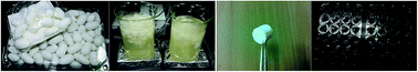
β-Chitin/silk fibroin/nanohydroxyapatite (CT/SF/nHAp) composite scaffolds were synthesized using a freeze-drying method by blending β-chitin hydrogel, silk fibroin and nHAp at different inorganic/organic weight ratios. The prepared nHAp and composite scaffolds were characterized using BET, SEM, EDS, FT-IR, XRD and TGA studies. The composite scaffolds were found to have 80–87% porosity with a well-defined interconnected porous construction. Moreover, the cell viability, attachment and proliferation using MTT, DMEM solution, and mouse preosteoblast cells proved the cytocompatible nature of the composite scaffolds with improved proliferation and cell attachment. These results imply that these materials have the ability to be candidates for bone tissue engineering applications.
Introduction
At present, tissue engineering has been used to develop biological substitutes for regenerating or repairing damaged tissue with the goal that it will help reconstruct the functions during the regeneration and ensuing combination with the host tissue.1,2 Natural bone is a complex inorganic–organic nanocomposite material with different material parts including about 70 wt% of mineral phases, chiefly hydroxyapatite, and 30 wt% of organic matrix, chiefly collagen fibrils. nHAp nanocrystals are embedded within collagen fibrils.3,4 For tissue engineering, a scaffold should be fabricated into a 3-dimensional construction with an appropriate pore size and high porosity. A scaffold must mimic the natural extracellular environment of the tissue and possess certain mechanical strength, the time-space matching charter of the degradation disappearance of materials and new tissue structure.6,7 Hydroxyapatite has been used widely for bone regeneration and biomedical implant applications. It is a biodegradable, non-inflammatory, non-toxic, biocompatible, non-immunogenic and bioactive material that has potential to form a direct chemical bond with surrounding hard tissues and osteoconductive attributes.8–10 Hydroxyapatite/organic composites illustrate sufficient bonding ability and biocompatibility with the surrounding host tissues inherent from nHAp. The problems associated with nHAp ceramic, such as intrinsic fragileness, migration of the nHAp particles from the implanted sites and poor formability can be improved by the adhesion of nHAp ceramic with biopolymers such as silk fibroin and chitin.11,12 Silk fibroin has been applied in cell transplantation due to its good mechanical strength, suitable bioaffinity strength, and high oxygen permeability. The addition of SF intensified the microhardness of the nHAp ceramic. However, the nHAp–SF composite cannot meet the requirements for bone replacement due to its inadequate flexibility and formability.12–16 Chitin can be used to solve these problems. It is known to be one of the natural hetero-polysaccharides with a low toxicity and biodegradability when implemented into an animal body.17–20 Studies have shown that the composite scaffolds comprised of chitosan with silk fibroin and hydroxyapatite improve the biodegradation and the osteoblast cell viability but their mechanical strength and formability are not good.21,22 Other multi component scaffolds and their features have been investigated by comparing them with bi-component scaffolds.23–26 However, the influence of nHAp on SF/CT composite scaffolds is not well understood. Following our recent study on the structure of composite scaffolds,27–29 in this study we focused on the fabrication, characterization, biomineralization, porosity, water-uptake capacity, biodegradation, bioactivity, mechanical and in vitro properties of nanocomposite scaffolds CT/SF/nHAp in detail.
Experimental section
Materials
β-Chitin (degree of acetylation 72.4%) was purchased from Koyo Chemical Co., Ltd., Japan. LiBr and other agents were purchased from Sigma-Aldrich. Raw cocoons of silkworm, Bombyx mori, were supplied from Sericulture Farm, Natanz, Iran. Cellulose dialysis cassettes (Slide-A-lyzer, MWCO 12
000 Da (Sigma)) were used to remove solvent impurities from the silk fibroin solution. For the in vitro study of cytotoxicity, a mouse preosteoblast cell line (MC3T3-E1) was purveyed by Riken Cell Bank (Ibaraki, Japan). Dulbecco's modified Eagle's medium (DMEM), ascorbic acid and MTT [3,4,5-dimethylthiazol-2yl{-2,5-diphenyl-2H-tetrazoliumbromide}] were purchased from Sigma-Aldrich, USA. Fetal bovine serum (FBS) was purchased from Wisent (Mon-trial, Canada). Hen lysozyme was purchased from Cell Bank, Pasteur Institute of Tehran.
Calcium solvent
Calcium solvent was prepared as described in the literature.30 To prepare a clear calcium solvent, we dispersed 850 g of CaCl2·2H2O in 1 L of methanol and refluxed it for 30 min, followed by allowing it to stand overnight at room temperature and filtration.
Preparation of β-chitin hydrogel
5 g of β-chitin was added to 1 L of the calcium solvent and vigorously stirred for 2 days at room temperature. The solution was filtered to remove the undissolved traces to obtain a clear β-chitin solution. Excess water was added to this solution to break the bond between chitin and CaCl2 and stirred vigorously for 2 h. After allowing it to stand overnight, the solution was filtered and dialyzed against distilled water for 48 h to obtain a pure β-chitin hydrogel.18
Preparation of regenerated silk fibroin
Bombyx mori silk cocoons were cut into fourths. Then, sericin was removed by boiling the cocoons in a 0.02 M Na2CO3 solution for 45 minutes. The fibroin extract was then washed with distilled water, dissolved in 9.3 M LiBr solution at room-temperature and warmed at 60 °C for 4 h. The solution was dialyzed with ultrapure water for 2 days to remove the residual LiBr and then centrifuged. Gravimetric analysis showed that the concentration of the derived aqueous silk solution was about 2.5 wt/vol%.31,32
Preparation of nHAp powder
nHAp was prepared according to the literature33 by adding a solution of 30 mmol (NH4)2HPO4 in 250 mL of double distilled water to a solution of 50 mmol Ca(NO3)2·4H2O in 600 mL of water. Then, 30 mL of ammonium hydroxide (30% in water) and an extra quantity of 5 mmol Ca(NO3)2·4H2O were added. The mixture was stirred powerfully and 10 mL of ammonium hydroxide was added after 5 h. The final mixture was stirred mildly for 12 h. Subsequently, the solution was filtered and washed with the double distilled water. The final product was dried at 80 °C for 15 h. The sample was pulverized and transferred into an ultrasonic bath filled with 300 mL of double distilled water for 15 min. Subsequently, this sample was filtered and dried. The obtained particles showed high crystallinity after calcination at 1000 °C for 1 h.
Preparation of composite scaffold
β-Chitin hydrogel was added into the silk solution and stirred for 12 h at 4 °C. Then, nHAp was added to the solution and stirred for 24 h to disperse nHAp in the silk solution. The resultant solution was suspended in an ultrasonic bath to further disperse the particles and reduce the particle size. Subsequently, 0.25% (v/v) of glutaraldehyde was added in 1
:
32 ratio (2 h) for cross-linking. The final solution was transferred to 24-well culture plates and pre-freezed at −20 °C for 12 h. This was followed by freeze-drying (Dena vacuum industry) at −80 °C for 48 h. The SF content of each specimen was scaled according to the CT/SF/nHAp weight ratios of 15/15/70, 25/25/50 and 35/35/30, which are listed in Table 1.
Table 1 Characteristics of the CT/SF/nHAp composites
CT/SF/nHAp composition (wt/wt) |
Characteristics of the composite scaffolds |
Porosity (%) |
Water-uptake capacity |
Scaffold surface/volume ratio (mm−1) |
Pore size (μm) |
15/15/70 |
80 ± 2.2 |
394 ± 35 |
290.45 ± 21 |
62 ± 4 |
25/25/50 |
85 ± 1 |
815 ± 26 |
272.05 ± 18 |
73 ± 5 |
35/35/30 |
87 ± 3 |
2157 ± 36 |
255.93 ± 25 |
80 ± 3 |
Characterization
The samples were characterized by X-ray diffraction (Bruker D8ADVANCE, Cu Kα radiation), FT-IR spectroscopy (Nicolet 400D in KBr matrix, with the range of 4000–350 cm−1), BET specific surface areas and BJH pore size distribution (Series BEL SORP 18, at 77 K) and SEM (Philips, XI30, SE detector). To investigate the weight loss of the CT/SF/nHAp composite scaffolds during thermogravimetric (TG) analysis, a test was carried out using a DuPont TGA 951 at temperatures ranging from room temperature to 450 °C in air and at a heating rate of 10 °C min−1. Energy-dispersive X-ray spectroscopy (EDS) analysis was performed on a SERON AIS 2300, Korea.
Porosity studies
The porosity of the scaffolds was evaluated using a liquid displacement approach.12 Hexane served as the displacement liquid because it is a non-solvent agent for silk and can be easily permeated through the scaffold without any shrinkage or swelling of the scaffold. Scaffolds were cut into 1 × 1 × 1 cm pieces and immersed in a cylinder containing a clarified volume of hexane (V1). The volume of hexane and the hexane-saturated scaffold was noted as V2 and obtained after the scaffold was placed in hexane for 1 h. The volume difference (V2 − V1) was the volume of the composite scaffold. The residual hexane volume in the graduated cylinder after the removal of the scaffold was recorded as V3. The quantity (V1 − V3), which is the volume of hexane within the scaffold, was defined as the void volume of the scaffold. The total volume of the scaffold was V = (V2 − V1) + (V1 − V3) = V2 − V3. The porosity of the scaffold (ε) was measured as follows: ε (%) = (V1 − V3)/(V2 − V3) × 100.
Water-uptake capacity
The scaffolds were immersed in water at room temperature for 48 h to help ensure water was saturated into the open pores. The water uptake of the porous samples was calculated as water-uptake (%) = (Ww − Wd)/Wd × 100, where Ww and Wd imply the wet weight of the sponges and initial dry weight scaffolds, respectively.
Mechanical properties
The compressive strength and modulus of the composite scaffolds were measured in the dry state at a crosshead speed of 2 mm min−1 in a material prufung 1446-60 machine (Zwick). The samples with a size of 1 × 1 × 1 cm were used in the compressive property test.
In vitro degradation
The degradation of the SF and (CT/SF/nHAp) composite scaffolds was examined in a PBS medium containing lysozyme (10
000 U mL−1) at 37 °C for different time intervals (1, 4, 7, 14, 21 and 28 days). Wo and Wt represent the initial weight and the dry weight of scaffolds, respectively. After a specified period, the scaffolds were washed in deionized water to remove the surface adsorbed ions and lyophilized. The degradation of the scaffolds was assayed using the following formula:
Degradation% = (Wo − Wt)/Wo × 100 |
The degradation rate was recorded as the mean ± SD (n = 5).
In vitro biomineralization
Composite scaffolds with equal weights and shapes were placed in simulated body fluid (SBF) solution and then incubated at 37 °C in closed Falcon tubes for various time intervals (1, 4, 7 and 14 days). The SBF solution was prepared as described in the literature.34 After each period, the scaffolds were washed three times with deionized water to remove the adsorbed minerals. After 7 and 14 days, the scaffolds were freeze-dried and characterized using SEM and EDS; after 14 days they were characterized using XRD and FT-IR for mineralization.
In vitro evaluation of cytotoxicity
MTT test was used to determine the relative cell viability.35 A mouse preosteoblast cell line MC3T3-E1 served to estimate the in vitro cytotoxicity of the extractions. The passaged (cells less than passage 7) and isolated cells were trypsinised, pilled and resuspended in a known amount of DMEM media. A cell concentration of 1 × 10⁵ cells per mL was transferred to 24-well tissue culture plates overnight. The samples were sterilized by placement in ethanol and this was followed by UV irradiation for 30 min. The scaffolds (1 cm × 1 cm × 1 cm) were immersed in separate sterile tubes with 5 mL of DMEM solution and incubated at 37 °C for 24 h. To examine the in vitro cytotoxicity of the extractions, a 4 mL extraction of each sample was collected. The culture media was changed with the extraction every 2 days. The MTT assay was managed in 1, 3 and 7 days by changing the media with MTT solution in the wells for 4 h. MTT solution was removed and formazan crystals were dissolved in DMSO. A microplate reader (Bio-RAD 680, USA) recorded the optical density using a spectrophotometer with a stimulus wavelength of 540 nm. DMSO served as a blank. The same numbers of cells in contact with culture media were used as the control groups.
Statistical analysis
Statistical analysis was performed using SPSS v.16.0 software. Data were expressed as the mean ± significant if ρ values obtained from the test were less than 0.05 (ρ < 0.05).
Results and discussion
Scanning electron microscopy (SEM)
SEM analysis has a variety of applications, especially in characterization of solid materials. In addition to topographical, morphological, detailed three-dimensional and compositional information, SEM can detect and analyze surface fractures, provide information on microstructures, examine surface contaminations, reveal spatial variations in chemical compositions, provide qualitative chemical analyses and identify crystalline structures. Fig. 1 illustrates the SEM micrographs of the samples. In pure chitin (Fig. 1a), the number of interconnected pores was high. The pure SF scaffold showed a macroporous structure with interconnected open pores with sizes ranging from 100 to 200 μm (Fig. 1b). The external morphology of the nHAp nanoparticles showed a nearly spherical shape with sizes varying from 74 to 110 nm (Fig. 1c). In the scaffolds, open interconnected pores could enhance fluid exchange and native tissue ingrowth (Fig. 1d–f). The nHAp particles made the pore walls rough. This was beneficial for cell adhesion. In the composite scaffolds, the amount of nHAp managed the average porosity and the degree of interconnectivity. As it is obvious from Fig. 1d–f, an increase in the amount of nHAp caused a decrease in the number of pores. The shift of nutrients, oxygen and cells was still maintained through pores despite the interactions between the polymer chains.
 |
| Fig. 1 SEM images of (a) pure CT, (b) pure SF, (c) pure nHAp, (d) composite 15/15/70, (e) composite 25/25/50, and (f) composite 35/35/30. | |
FT-IR spectroscopy
As a characterization tool, infrared spectroscopy can provide certain structural clues to the overall molecular structure of an unknown substance. IR spectroscopy is a simple and reliable technique widely used in both organic and inorganic chemistry. Fig. 2 illustrates the FT-IR spectra of the samples in the spectral range of 4000–400 cm−1. The peaks at 1625 ± 5 cm−1 (amide I), 1525 ± 5 cm−1 (amide II) and 1265 ± 5 cm−1 (amide III) were attributed to the silk II structural conformation (β-sheet). The absorption bands at 1520 cm−1 (amide II) and 1226 cm−1 (amide III) are related to the silk I structural form (random coil and α-helix) (Fig. 2a). The FT-IR spectrum of chitin showed peaks at 3430 cm−1 (O–H stretching vibration), 1601 cm−1 (amide I), and 1392 cm−1 (C–CH3 bending) (Fig. 2b).18 The FT-IR spectrum of nHAp presented peaks at 632 and 3430 cm−1, which were related to the –OH bending and stretching vibration modes. The band at 473 cm−1 corresponded to γ2 of phosphate, the band at 602 and 567 cm−1 was characteristic for γ4 of phosphate, the one at 963 cm−1 referred to γ1 of phosphate and the other at 1042 cm−1 attributed to γ3 of phosphate (Fig. 2c).36 The absorption bands at 1551 and 1239 cm−1 could be characteristic of the amide II and amide III of SF in the CT/SF/nHAp composite scaffolds.35 Moreover, the band at 1628 cm−1 corresponded to the characteristic absorption of the OH group of nHAp, which appeared as a sharper peak at 1656 cm−1 in the CT/SF/nHAp composite scaffolds, perhaps due to the overlap of the bands of OH group in nHAp and amide I in SF. The IR spectra of all these composite scaffolds (Fig. 2d–f) showed the typical peak of phosphate vibrations at 1042 cm−1, which implied the existence of nHAp on the surface of the composite scaffolds. The OH absorption of silk fibroin in the CT/SF/nHAp composite scaffolds can be observed at 3284–3430 cm−1, which becomes wider than that found for silk fibroin itself. Thus, the characteristic absorptions of OH in the CT/SF/nHAp composite scaffolds suggested the formation of hydrogen bonds between the nHAp crystals, SF and CT. The hydrogen bonds may also be existing between the –NH2 groups and nHAp (Fig. S1†).35 From the spectra (Fig. 2d–f) it was found that the incorporation of nHAp into the β-chitin hydrogel caused the broadening of the peak at 3430 cm−1 (characteristic of β-chitin), which was due to the intermolecular hydrogen bonding between the –NH2 groups of β-chitin and the –OH groups of nHAp. The characteristic peaks of nHAp were present in the spectra of the composite scaffolds. The intensity of the peaks at 567 and 602 cm−1 was less in the (Fig. 2f) scaffold because the concentration of nHAp was less. However, in the (Fig. 2d) scaffold, the peaks were resolved and intensity was also increased.19 The SF fibers first precipitated from the solution and stretched into a β-sheet structure; hence, more hydrophilic groups such as –NH– and –COO– were exposed on the surface and adsorbed inorganic ions (e.g. Ca2+). Only when a certain interplanar distance of nHAp matched with the space of the amino acid molecule such as aspartic acid (ASP) in SF, the nHAp particles could grow longer in this direction. Because of the formation of the SF–metallic ion chelate, Ca2+ was fixed on the functional groups. The nHAp and SF organically cross-linked together to form a structure similar to that of the natural bone (Fig. S1†).37
 |
| Fig. 2 FT-IR spectra of (a) pure SF, (b) pure CT, (c) pure nHAp, (d) composite 15/15/70, (e) composite 25/25/50, and (f) composite 35/35/30. | |
XRD analysis
X-ray diffraction has led to a better understanding of the chemical bonds and non-covalent interactions. Fig. 3a–f shows the X-ray diffraction patterns of the composite scaffolds with weight ratios of nHAp and pure nHAp. The peaks of the synthesized nHAp particles matched with the characteristic XRD spectrum of HAp (JCPDS File no. 09-0432). Sharp diffractions were attributed to the (211), (112), (300), (002), (213), (222), (202), (310), and (321) reflections of the nHAp crystal, respectively. These proved that nHAp was composed of well-developed crystals. Pure diffraction peaks at 2θ = 11.5° and 22.8° correspond to the crystal structure of the anhydrous form of CS and the diffraction peaks at about 2θ = 20–30° could be related to a β-sheet (silk II) structure.3,14 The three nanocomposites display peaks at similar positions assigned only to the monophase crystalline nHAp, because no diffraction peaks from other calcium phosphate phases were observed. This implies that the addition of SF and CT did not change the crystalline structure of nHAp. The XRD patterns show a preferential growth of the nHAp crystallites along the c-axis in all three nanoparticles, because the intensity of the (002) peak was higher than that of the (300) peak.21 The XRD patterns of the composites simultaneously represented the distinctive peaks of the nHAp, random coil and silk II structure.37 In the 35/35/30 composite scaffold, the peaks had intensities less than those with the higher concentration of nHAp. The intensity of the peaks related to SF were decreased in the case of the nHAp incorporated composite scaffolds.
 |
| Fig. 3 XRD patterns of (a) pure nHAp, (b) composite 15/15/70, (c) composite 25/25/50, and (d) composite 35/35/30. | |
BET analysis
The N2 adsorption–desorption isotherms for the CT/SF/nHAp scaffold are shown in Fig. S2.† The isotherms were similar to the type III isotherm with H3-type hysteresis loops at high relative pressure based on the IUPAC classification. This is assigned to porous materials with highly similar size distributions.38,39 From the two branches of the adsorption–desorption isotherms, the presence of a sharp adsorption step in the P/P0 region from 0.9–1.00 and a hysteresis loop at a relative pressure of P/P0 greater than 0.8 shows that the materials are composed of well-defined and arranged porous materials. The specific surface area and the pore volume were calculated using the Brunauer–Emmett–Teller (BET) and Barrett–Joyner–Halenda (BJH) methods, respectively. The structural data of the material BET showed that the 15/15/70 composite scaffold had a high BET surface area (5.364 m2 g−1) and a large pore volume (0.020 cm3 g−1), expressive of its application as the maximum cell growth by attachment to the scaffold surfaces.
Thermogravimetric analysis (TGA)
The thermal stability of the composite scaffolds was evaluated by thermogravimetric analysis. Thermogravimetric analysis (TGA) was carried out to determine the thermal behavior and compositional fraction of the nanocomposite scaffolds. The TGA curves of pure nHAp and the CT/SF/nHAp composite scaffolds are displayed in Fig. 4. The TGA curve for pure nHAp particles shows a continuous weight loss of 8%, which can be related to water evaporation. There was no weight loss observed above 400 °C, which showed that pure nHAp was thermally stable at high temperatures. The weight of the three composite scaffolds decreases quickly with increasing temperature. The initial weight loss occurred around 100 °C, which was assigned to the loss of moisture. The thermal decomposition of the organic component in the CT/SF/nHAp composite scaffolds occurred mostly in the range of 200–350 °C. The organic components were decomposed completely at 400 °C. Because the inorganic phase of the composite scaffold (d) is less than that of the others, its thermal stability is less than the others. The organic/inorganic weight ratio in the CT/SF/nHAp composite scaffold (a) except from water content was computed to be 28.6/71.4, which was similar to the theoretical weight ratio (30/70). Thermal analysis showed that the SF and CT molecules efficiently interacted with the nHAp.3,20,21
 |
| Fig. 4 TG curves of samples. | |
Porosity measurements
An ideal scaffold to be used for bone tissue engineering should possess the characteristics of good biocompatibility, controllable biodegradability, cytocompatibility and suitable mechanical features. It should be able to promote cell attachment and allow the retention of the metabolic functions of the attached cells.40 The biodegradability of composite scaffolds can be altered by changes in the physicochemical and mechanical characteristics, such as weight loss and porosity of the materials after immersing in a physiological solution.41 Porosity is defined as the percentage of void space in a solid and plays an important role in the mechanical properties.42
Pores are necessary for bone tissue growth because they allow migration, expansion and proliferation of osteoblasts cells while maintaining transport. Moreover, a porous surface increases the mechanical interlocking between the natural bone and implanted biomaterial, providing better mechanical stability at this interface.43 The Young's modulus of bone is well known to be reduced by porosity. It is obvious that the Young's modulus of bone is also powerfully dependent on the mineral amount of the bone material. The mineral content of bone tissue, stiffness and strength vary inversely with the increasing porosity of bone tissue.44
Some studies on the porosity and mechanical properties of different composite scaffolds containing silk fibroin in tissue engineering applications are shown in Table 2.
Table 2 Porosity and mechanical properties of different composite scaffolds containing silk fibroin
Composite |
Method |
Porosity (vol%) |
Compressive strength |
Compressive modulus |
Ref. |
Hydroxyapatite/chitosan–silk fibroin |
Coprecipitation |
— |
179.3 ± 4.6 (MPa) |
— |
3 |
Chitosan/fibroin–hydroxyapatite |
Thermally induced phase separation |
More than 94 |
2.5–4.5 (gf mm−2) |
— |
5 |
Silk fibroin–chitosan/nano-hydroxyapatite |
Freeze-drying |
78–91 |
0.26–1.96 (MPa) |
— |
6 |
Silk fibroin/hydroxyapatite |
Blending |
55–75 |
19.9–28.7 (MPa) |
— |
10 |
Silk fibroin/chitosan |
Freeze-drying |
95.43 |
0.16–0.27 (MPa) |
2.51–6.53 (MPa) |
14 |
Silk/forsterite |
Freeze-drying |
83.2–91.6 |
1.2–4.6 (MPa) |
1.2–4.6 (MPa) |
22 |
Diopside/silk fibroin |
Freeze-drying |
70–88.12 |
0.12–0.46 (MPa) |
1–4.3 (MPa) |
27 |
Silk fibroin–chitosan/nano ZrO2 |
Freeze-drying |
79.4 |
0.55 (MPa) |
2 (MPa) |
28 |
Silk fibroin/chitosan |
Freeze-drying |
More than 90 |
100–300 (kPa) |
40–62 (kPa) |
31 |
β-Chitin/silk fibroin/nanohydroxyapatite |
Freeze-drying |
80–87 |
0.13–0.88 (MPa) |
1.3–8.2 (MPa) |
This work |
The porosities of the synthesized scaffolds are shown in Fig. S3.† When the amount of SF was increased from 15 to 35 wt%, the porosities were increased from about 80–87%. This was adequate to supply a chance for nutrient transport interconnection and cell migration.35 The crash of the thicker pore walls with the expected agglomeration of nHAp particles along with the increase in nHAp content (the decrease in SF content) inside them causes the reduction in the porosities. The pore sizes were affected by the time for the growth of ice crystals.
Water-uptake capacity
Water-uptake studies of SF and CT/SF/nHAp composite scaffolds showed a very high water-uptake capacity and the ability to keep water more than their original weight (Fig. S4†). The addition of nHAp decreased the water-uptake of the CT/SF/nHAp composite scaffolds.45,46 Because nHAp created cross-links between the chains, it decreased the hydrophilicity of chitin and silk fibroin by binding calcium and phosphate to the hydrophilic OH or NH groups.6,35 It was observed that as the concentration of SF increased, the water-uptake ratio also increased. The OH groups cannot form hydrogen bonds because some of the NH are bound to Ca groups, hence there is a decrease in water-uptake properties. Water-uptake promotes the cells penetration into the scaffolds in a 3-dimensional design, during cell culture. In addition, water-uptake increases the pore size and total porosity of the scaffolds. Composite scaffolds showing a higher water-uptake capacity will have a larger surface area/volume ratio. This gives the maximum chance of cell permeation into the scaffold. Thus, cell growth was enhanced by adhesion to the scaffold surfaces. The increase in water-uptake also allowed the samples to obtain nutrients from the culture media more impressively. However, while the water-uptake of scaffolds would improve cell attachment, it could degrade its mechanical properties.
Mechanical properties
As mentioned in the Introduction section, natural bone is a complex organic–inorganic nanocomposite material, in which nHAp (mineral phase) and collagen fibrils (organic matrix) are well organized into a hierarchical architecture over several length scales. This harmony endows natural bone with good mechanical properties such as high resistance to tensile and compressive forces, low stiffness, appreciable flexibility and high fracture toughness.3 Appropriate mechanical properties are essential to offer the correct stress environment for the neo-tissue; the mechanical strength of the scaffold should be sufficient to provide mechanical stability for withstanding the stress before the synthesis of the extracellular matrix by the cells.47 Mechanical cues of the cell microenvironment play a significant role in regulating cell behaviors such as migration, cell spreading, differentiation and proliferation.48 Many researchers have shown that the decreased pore size and increased thickness of the pore walls can result in a higher compressive strength and modulus. The compressive strength was increased inversely with pore size, which could be described by a decrease in strut strength with increasing pore size. The decrease in pore size and an increase in wall thickness through the addition of nHAp were responsible for the better mechanical stability observed in the composite scaffolds as compared to the silk fibroin scaffolds. The M. Gibson and Ashby model has generally been applied to relate the modulus to the density of foams. This model is valid in the elastic field only and is based upon the relation: E/Es = C1(ρ/ρs)2, where E is the elastic modulus of the metal foam, Es is the elastic modulus of the composite, ρ/ρs is the relative density, and C1 is a constant (C1 ≈ 1). An increase in the relative density of the structure improved the Young's modulus. As smaller struts appear denser, they, therefore, have significantly better mechanical properties. Based on Gibson and Ashby's model, it has been accepted that the compressive modulus of the composite scaffolds was increased with decreasing porosity and increased with the addition of nHAp.22
The composite scaffolds should have an appropriate porosity for cell growth, but they must also have good mechanical strength to support the structure during tissue regeneration. The tenacity of the composite scaffolds was compared based on the amount of nHAp. In this study, the influence of nHAp incorporation on the compressive strength (Fig. 5A) and compressive modulus (Fig. 5B) of the composite scaffolds was evaluated. The addition of nHAp increased the pore wall thickness and reduced the pore size, which were responsible for the high mechanical properties of the composite scaffolds, in comparison to the silk fibroin scaffolds.
 |
| Fig. 5 Mechanical properties of SF and composite scaffolds with various weight percentages of SF: (A) compressive strength and (B) compressive modulus. Values are the mean ± SD (n = 5). | |
In vitro degradation studies
Fig. 6 illustrates the degradation profiles of the composite scaffolds after incubation in PBS solution at 37 °C under pH = 7.4 conditions for 4 weeks. It was presumed that the macromolecules in the scaffolds surface tolerated significant hydrolytic scission into small molecules (oligomeric units), which could be dissolved in PBS.19,46 The results show that with increased degradation time, the decrease in mass was minor in all the scaffolds, although the transparency of the solution had a pronounced change. The percentage of weight loss for all the composites was less than 20% after 28 days. The degradation rate of pure SF was lower than the composite scaffolds. The scaffolds degradation rate was decreased upon the addition of nHAp into the composite. Chitin could be degraded using lysozyme present in the human body. The samples were degraded more in the lysozyme solution with a high concentration of chitin. The degradation products could further help to get more cells to the scaffold. Thus, it promoted the bioactivity of the scaffolds.20,49 These results showed that the degradation of the composite scaffolds could be controlled by changing the nHAp or chitin concentration.
 |
| Fig. 6 Degradation behavior vs. time curve for the scaffolds in PBS containing lysozyme at 37 °C. | |
The degradation rates of the fabricated scaffolds used in this study in comparison with those reported earlier for other biodegradable materials used in tissue engineering are shown in Table 3.
Table 3 Comparison of the degradation rate of the fabricated scaffolds used in this study with results of other authors
Scaffold content |
Environment |
Period (day) |
Degradation% |
Ref. |
Chitosan–gelatin/nanohydroxyapatite |
PBS containing lysozyme |
7 |
Around 20 |
1 |
Carbon nanotube-grafted-chitosan–natural hydroxyapatite |
PBS |
30 |
Around 10 |
7 |
Silk fibroin/chitosan |
PBS |
28 |
16.65 |
14 |
Chitin–chitosan/nanoZrO2 |
PBS containing lysozyme |
7 |
25 |
17 |
β-Chitin hydrogel/nano hydroxyapatite |
PBS containing lysozyme |
28 |
30 |
19 |
α-Chitin hydrogel/nano hydroxyapatite |
PBS containing lysozyme |
28 |
30–40 |
20 |
Silk/forsterite |
PBS |
28 |
Around 30 |
22 |
Silk fibroin–chitosan/nano ZrO2 |
PBS |
28 |
35 |
28 |
Silk fibroin protein and chitosan polyelectrolyte |
PBS containing lysozyme |
28 |
30 |
31 |
β-Chitin/silk fibroin/nanohydroxyapatite |
PBS containing lysozyme |
28 |
Around 20 |
This work |
As previously mentioned, nHAp has been used widely as a scaffold material in tissue engineering applications. There are several advantages to the freeze-drying method, including use of water and ice crystals instead of an organic solvent in the scaffold fabrication process, which is more suitable for biomedical applications. In this study, by controlling the freeze-drying parameters such as pre-freezing temperature and rate of cooling, the available time for the growth of ice crystals could be increased. This resulted in larger pore sizes and at the same time an increased crystallinity.27,50 Some studies on the applications of nHAp in tissue engineering applications are shown in Table 4.
Table 4 Some studies on nHAp based systems for bone tissue engineering
Scaffold content |
Preparation method |
In vitro testing |
Ref. |
Mechanical properties |
Cell culture studies on scaffold |
Chitosan–gelatin/nanohydroxyapatite |
Freeze-drying |
Increased tensile strength |
High cell attachment and high cell viability |
1 |
Carbon nanotube-grafted-chitosan–natural hydroxyapatite |
Freeze-drying |
Good mechanical strength |
High cell proliferation |
7 |
α-Chitin hydrogel/nano hydroxyapatite |
Freeze-drying |
— |
Cytocompatible |
20 |
Chitosan/nano-hydroxyapatite/nano-silver |
Freeze-drying |
Good mechanical strength |
Non-toxic to rat osteoprogenitor cells and human osteosarcoma cell line |
25 |
CT/SF/nHAp |
Freeze-drying |
Gradually increased |
Good cell attachment and good cell viability |
This work |
In vitro biomineralization studies
The scaffolds presented good potential to undergo mineralization at physiological pH and temperature in SBF solution. The apatite deposition morphology became different after 7 and 14 days of incubation. After these periods of incubation in 1 × SBF, minerals were observed to deposit on the surface of the pores. The EDS spectra of the composite scaffolds confirmed the presence of calcium and phosphate peaks with a Ca/P ratio ranging from 1.52 to 2.50 in all the samples. The theoretical value was 1.83. These results indicate the formation of a Ca rich apatite (Fig. 7). The FTIR spectra displayed in Fig. 8 show bands at 1037 cm−1 and 1135 cm−1 that are the characteristic bands of phosphate stretching vibrations, while the bands at 629 and 597 cm−1 are due to phosphate bending vibrations. The absorption peaks at 827 cm−1 and 1384 cm−1 correspond to carbonate (CO32−) and could be clearly observed in the FT-IR spectra. There are many nHAp particles on the composite scaffolds, which operate as nucleation sites decreasing the surface energy minerals. Thus, apatite could be created more impressively in the composite containing 70% nHAp (15/15/70) than in those containing 30% nHAp (35/35/30). It has been implied that the formation of apatite on the composite scaffolds was influenced by negatively charge functional groups, which could further impel the formation of apatite by the formation of amorphous calcium phosphate.49 Once the apatite nuclei were formed, they can grow naturally using the phosphate and calcium ions present in the medium. The X-ray diffraction patterns of the composite scaffolds are shown in Fig. 9. The peaks for calcium phosphate particles that attribute to the characteristic XRD spectrum of Ca2P2O7 (JCPDS File no. 03-0605) became intense upon the addition of nHAp.
 |
| Fig. 7 SEM and EDS images of (a) composite 15/15/70, (b) composite 25/25/50, and (c) composite 35/35/30, after soaking in SBF solution for 7 days and (d) composite 15/15/70, (e) composite 25/25/50, and (f) composite 35/35/30 for 14 days. | |
 |
| Fig. 8 FT-IR spectra of (a) composite 15/15/70, (b) composite 25/25/50, and (c) composite 35/35/30 when immersed in SBF solution for 14 days. | |
 |
| Fig. 9 XRD patterns of (a) composite 15/15/70, (b) composite 25/25/50, and (c) composite 35/35/30 when immersed in SBF solution for 14 days. | |
The XRD patterns around the characteristic regions (2θ = 31.7°, 32.9°, 39.8°, 46.7°, 49.4° and 50.4°) reduced partially with a low content of HAp. The immersion process caused more HAp particles to be exposed and thus induced the deposition of more HAp crystals.
These results show that the addition of nHAp increased the bioactivity of the composite scaffolds.
In vitro evaluation of cytotoxicity
For cell transplantation in tissue engineering, the scaffolds should be biocompatible and non-toxic to bone cells. Thus, the scaffold materials were examined by subjecting them to mouse preosteoblast cells. The proliferation of MC3T3-E1 cells in contact with the extraction of the scaffolds was investigated after 7 days of culture using an MTT assay (Fig. 10). The addition of SF (with a decrease in the nHAp content) increased the cell proliferation of the CT/SF/nHAp composite scaffolds. This could be as a result of the low crystallinity of the nHAp, resulting in the dissolution of phosphate and calcium into the media.1 This, sequentially, lead to an increase in intracellular Ca and phosphate concentration, which caused more cell death. There were notable differences between days 1, 3 and 7 for all the groups. As a positive control, cells incubated with Triton X-100 illustrated a major loss of cell viability. The results revealed an evident increase in cell numbers over time. It was observed that the CT/FS/nHAp composite scaffolds were cytocompatible, showing that these scaffolds were non-toxic to osteoblastic cells.
 |
| Fig. 10 In vitro cytotoxicity evaluation of MC3T3 cells in contact with the scaffolds for different periods of time. Data are presented as the mean ± SD. Significant difference (p ≤ 0.05). | |
Cell attachment studies
SEM imaging was used to study the attachment and morphology of the cells on the surface of the scaffolds. The morphology of the cells was flattened and sheet-like with filopodial extension, as seen in the SEM images. Fig. S5a and b† represent the typical scanning electron micrographs of the nanocomposite scaffold after 7 days of incubation in the cell culture medium alone and after incubation with cells. The higher attachment on the nanocomposite scaffolds may be due to the increase in surface area. An increase in the surface area allows maximum area for cell attachment, and nanosurfaces have a larger surface area to volume ratio. The presence of nHAp in the scaffolds help to adsorb more proteins on the scaffold surfaces as well. These adsorbed proteins attract more number of cells towards those regions and thus enhance the attachment and proliferation. The results indicate that the CT/SF/nHAp nanocomposite scaffolds might be suitable for tissue engineering applications.
Conclusions
CT/SF/nHAp composite scaffolds were synthesized using a freeze-drying approach. The resulting scaffolds were characterized and compared. The composite scaffolds were found to have favorable pore size and porosity. The mechanical and biological characteristics of the scaffolds were influenced by the addition of nHAp and by changing the ratio of CT and SF in the scaffold. The mechanical and biological properties of the scaffolds were significantly affected by the addition of nHAp. When nHAp was added to CT and SF, the density was increased and biodegradability decreased with a small change in pore size. The increase in density was related to a decrease in water-uptake capacity and a decrease in the total porosity. nHAp substantially improved cell attachment on the scaffold surfaces. Thus, nHAp played a major role in improving the biological and mechanical properties of the scaffolds. The addition of nHAp to CT and SF provided a more promising scaffold for use in bone tissue engineering applications.
Acknowledgements
Support from the Payame Noor University in Isfahan Research Council (Grant # 84910) and contribution from the Isfahan University of Technology are gratefully acknowledged. The authors would like to thank Dr H. Jalali for reading the manuscript.
References
- M. Peter, N. Ganesh, N. Selvamurugan, S. V. Nair, T. Furuike, H. Tamura and R. Jayakumar, Carbohydr. Polym., 2010, 80, 687–694 CrossRef CAS.
- K. Madhumathi, N. S. Binulal, H. Nagahama, H. Tamura, K. T. Shalumon, N. Selvamurugan, S. V. Nair and R. Jayakumar, Int. J. Biol. Macromol., 2009, 44, 1–5 CrossRef CAS PubMed.
- L. Wang and C. Li, Carbohydr. Polym., 2007, 68, 740–745 CrossRef CAS.
- S. Wu, X. Liu, K. W. K. Yeung, C. Liu and X. Yang, Mater. Sci. Eng., R, 2014, 80, 1–36 CrossRef.
- H. S. Kim, J. T. Kim and Y. J. Jung, Macromol. Res., 2007, 15, 65–73 CrossRef CAS.
- G. Wen, J. Wang, M. Li and X. Meng, Key Eng. Mater., 2007, 330, 971–975 CrossRef.
- J. Venkatesan, Z. J. Qian, B. Ryu, N. A. Kumar and S. K. Kim, Carbohydr. Polym., 2011, 83, 569–577 CrossRef CAS.
- M. C. Chang, J. Korean Ceram. Soc., 2008, 45, 573–578 CrossRef CAS.
- M. Kazemzadeh Narbat, F. Orang, M. Solati Hashtjin and A. Goudarzi, Iran. Biomed. J., 2006, 10, 215–223 Search PubMed.
- L. Shen-zhou, L. Jia-jia, Y. Shu-qin, L. Jian-bing and L. Ming-zhong, J. Clin. Rehabil. Tissue Eng. Res., 2009, 13, 6789–6792 Search PubMed.
- K. Madhumathi, P. T. Sudheesh Kumar, K. C. Kavya, T. Furuike, H. Tamura, S. V. Nair and R. Jayakumar, Int. J. Biol. Macromol., 2009, 45, 289–292 CrossRef CAS PubMed.
- R. Nazarov, H. J. Jin and D. L. Kaplan, Biomacromolecules, 2004, 5, 718–726 CrossRef CAS PubMed.
- E. S. Gil, D. J. Frankowski, S. M. Hudson and R. J. Spontak, Mater. Sci. Eng., C, 2007, 27, 426–431 CrossRef CAS.
- Z. She, B. Zhang, C. Jin, Q. Feng and Y. Xu, Polym. Degrad. Stab., 2008, 93, 1316–1322 CrossRef CAS.
- C. Veparia and D. L. Kaplan, Prog. Polym. Sci., 2007, 32, 991–1007 CrossRef PubMed.
- M. A. Meyers, P. Y. Chen, A. Y. M. Lin and Y. Seki, Prog. Mater. Sci., 2008, 53, 1–206 CrossRef CAS.
- R. Jayakumar, R. Ramachandran, P. T. S. Kumar, V. V. Divyarani, S. Srinivasan, K. P. Chennazhi, H. Tamura and S. V. Nair, Int. J. Biol. Macromol., 2011, 48, 336–344 CrossRef CAS PubMed.
- P. T. S. Kumar, S. Abhilash, K. Manzoor, S. V. Nair, H. Tamura and R. Jayakumar, Carbohydr. Polym., 2010, 80, 761–767 CrossRef CAS.
- P. T. S. Kumar, S. Srinivasan, V. K. Lakshmanan, H. Tamura, S. V. Nair and R. Jayakumar, Carbohydr. Polym., 2011, 85, 584–591 CrossRef.
- P. T. S. Kumar, S. Srinivasan, V. K. Lakshmanan, H. Tamura, S. V. Nair and R. Jayakumar, Int. J. Biol. Macromol., 2011, 49, 20–31 CrossRef CAS PubMed.
- J. He, D. Wang and S. Cui, Polym. Bull., 2012, 68, 1765–1776 CrossRef CAS.
- A. Teimouri, L. Ghorbanian, A. Najafi Chermahini and R. Emadi, Ceram. Int., 2014, 40, 6405–6411 CrossRef CAS.
- X. Qi, Z. Mou, J. Zhang and Z. Zhang, J. Biomed. Mater. Res., 2014, 102, 366–372 CrossRef PubMed.
- L. Jiang, Y. Li, X. Wang, L. Zhang, J. Wen and M. Gong, Carbohydr. Polym., 2008, 74, 680–684 CrossRef CAS.
- S. Saravanan, S. Nethala, S. Pattnaik, A. Tripathi, A. Moorthi and N. Selvamurugan, Int. J. Biol. Macromol., 2011, 49, 88–93 CrossRef PubMed.
- S. N. Danilchenko, O. V. Kalinkevich, M. V. Pogorelov, A. N. Kalinkevich, A. M. Sklyar, T. G. Kalinichenko, V. Y. Ilyashenko, V. V. Starikov, V. I. Bumeyster, V. Z. Sikora, L. F. Sukhodub, A. G. Mamalis, S. N. Lavrynenko and J. J. Ramsden, J. Biol. Phys. Chem., 2009, 9, 119–126 CrossRef CAS.
- L. Ghorbanian, R. Emadi, S. M. Razavi, H. Shin and A. Teimouri, Int. J. Biol. Macromol., 2013, 58, 275–280 CrossRef CAS PubMed.
- A. Teimouri, R. Ebrahimi, R. Emadi, B. Hashemi Beni and A. Najafi Chermahini, Int. J. Biol. Macromol., 2015, 76, 292–302 CrossRef CAS PubMed.
- A. Teimouri, R. Ebrahimi, A. Najafi Chermahini and R. Emadi, RSC Adv., 2015, 5, 27558–27570 RSC.
- H. Tamura, H. Nagahama and S. Tokura, Cellulose, 2006, 13, 357–364 CrossRef CAS.
- N. Bhardwaj and S. C. Kundu, Carbohydr. Polym., 2011, 85, 325–333 CrossRef CAS.
- N. Bhardwaj, S. Chakraborty and S. C. Kundu, Int. J. Biol. Macromol., 2011, 49, 260–267 CrossRef CAS PubMed.
- C. Stotzel, F. A. Muller, F. Reinert, F. Niederdraenk, J. E. Barralet and U. Gbureck, Colloids Surf., B, 2009, 74, 91–95 CrossRef CAS PubMed.
- T. Kokubo and H. Takadama, Biomaterials, 2006, 27, 2907–2915 CrossRef CAS PubMed.
- J. Li, Y. Dou, J. Yang, Y. Yin, H. Zhang, F. Yao, H. Wang and K. Yao, Mater. Sci. Eng., C, 2009, 29, 1207–1215 CrossRef CAS.
- J. K. Han, H. Y. Song, F. Saito and B. T. Lee, Mater. Chem. Phys., 2006, 99, 235–239 CrossRef CAS.
- K. S. Katti, D. R. Katti and R. Dash, Biomed. Mater., 2008, 3, 034122 CrossRef PubMed.
- B. D. Zdravkov, J. J. Cermak, M. Sefara and J. Janku, Cent. Eur. J. Chem., 2007, 5, 385–395 CrossRef CAS.
- K. S. W. Sing, D. H. Everett, R. A. W. Haul, L. Moscou, R. A. Pierotti, J. Rouquero and T. Siemieniewska, Pure Appl. Chem., 1985, 57, 603–619 CrossRef CAS.
- W. W. Thein-Han, J. Saikhun, C. Pholpramoo, R. D. K. Misra and Y. Kitiyanant, Acta Biomater., 2009, 5, 3453–3466 CrossRef CAS PubMed.
- C. Chen, C. Wang, N. Hsueh and S. Ding, J. Alloys Compd., 2014, 585, 25–31 CrossRef CAS.
- M. B. Schaffler and D. B. Burr, J. Biomech., 1988, 21, 13–16 CrossRef CAS PubMed.
- V. Karageorgiou and D. Kaplan, Biomaterials, 2005, 26, 5474–5491 CrossRef CAS PubMed.
- J. D. Currey, J. Biomech., 1988, 21, 131–139 CrossRef CAS PubMed.
- R. J. Nordtveit, K. M. Varum and O. Smidsrod, Carbohydr. Polym., 1996, 29, 163–167 CrossRef CAS.
- H. W. W. Thein and R. D. K. Misra, Acta Biomater., 2009, 5, 1182–1197 CrossRef PubMed.
- N. Bolgen, Y. Yang, P. Korkusuz, E. Guzel, A. J. El Haj and E. Piskin, Tissue Eng., Part A, 2008, 14, 1743–1750 CrossRef PubMed.
- G. Huang, L. Wang, S. Wang, Y. Han, J. Wu, Q. Zhang, F. Xu and T. J. Lu, Biofabrication, 2012, 4, 042001 CrossRef PubMed.
- A. P. Marques and R. L. Reis, Mater. Sci. Eng., C, 2005, 25, 215–229 CrossRef.
- T. Lu, Y. Li and T. Chen, Int. J. Nanomed., 2013, 8, 337–350 CrossRef PubMed.
Footnote |
† Electronic supplementary information (ESI) available. See DOI: 10.1039/c5ra22987a |
|
This journal is © The Royal Society of Chemistry 2016 |
Click here to see how this site uses Cookies. View our privacy policy here.