The excellent cycling stability and superior rate capability of polypyrrole as the anode material for rechargeable sodium ion batteries

Xiaoying Chen, Li Liu*, Zichao Yan, Zhifeng Huang, Qian Zhou, Guoxiong Guo and Xianyou Wang*
Key Laboratory of Environmentally Friendly Chemistry and Applications of Ministry of Education, School of Chemistry, Xiangtan University, Xiangtan 411105, Hunan, China. E-mail: liulili1203@126.com; wxianyou@yahoo.com; Fax: +86-731-58292477; Tel: +86-731-58292206

Received 28th October 2015 , Accepted 10th December 2015

First published on 14th December 2015


Abstract

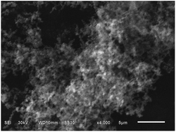
Polypyrrole with a submicrostructure has been successfully synthesized via a simple chemical oxidative polymerization. As characterized by X-ray diffraction, Fourier transform infrared (FTIR) spectroscopy, and scanning electron microscopy (SEM), the submicron polypyrrole shows a fluffy structure comprised chains composed of submicron particles. The submicron polypyrrole shows excellent electrochemical performance as the anode material for sodium ion batteries, which is much better than bulk polypyrrole. It displays a stable discharge capacity of 183 mA h g−1 at 400 mA g−1 after 100 cycles, whereas only 34.8 mA h g−1 for bulk polypyrrole under the same conditions. Furthermore, the submicron polypyrrole shows an extremely stable storage capacity during long term cycling even at super high rates. Except the irreversible capacity for the first cycle, the specific capacity remains stable and still maintains at 84 mA h g−1 after 500 cycles at 14[thin space (1/6-em)]400 mA g−1. The remarkable electrochemical performance greatly suggests that the submicron polypyrrole is an advanced anode material for sodium ion batteries.

1. Introduction

Cheaper, safer, and more eco-friendly advanced energy storage as a candidate for future renewable energy storage has caused extensive concern.1 Historically, studies on Li+ and Na+ ions as charge carriers for electrochemical energy storage at room temperature started before 1980. However, over the past several decades, most significant efforts have been conducted for lithium-ion batteries (LIBs) only and studies on sodium insertion materials for electrochemical storage once almost disappeared.2 Recently, with the environmental disruption of burning non-renewable fossil fuels and the shortage of lithium resources, sodium ion batteries (NIBs) have aroused renewed interest as a promising alternative to LIBs for future electrochemical energy storage.3 When compared with LIBs, NIBs possess superior advantages, such as being more eco-friendly, their widespread availability and the low cost of sodium resources, have attracted the world's attention.4–6 However, among all this study, the functional material (especially the anode material) has been considered to be one of the most crucial restrictions for the wider application of NIBs.

The absence of suitable negative electrodes has limited the development of NIBs for a long period of time. Sodium metal cannot be used as a host of sodium ions due to the possibility of dendrite formation at low potential and the low melting temperature of sodium metal from safety concerns.7 Therefore, it is of great urgency to find a perfect anode material for future NIBs. More recently, sodium ion insertion into carbon anode materials has been extensively studied by a number of researchers.8–10 Unfortunately, the results show that unless high pressures are used, sodium ion insertion into graphitic carbons is minimal. As the first turning point in the study of anode materials for NIBs, hard carbon with high discharge capacity and good capacity retention has also been studied even though its cyclability was insufficient for battery applications.11 However, there may be sodium dendrite formation at the low voltage discharge plateau between 0 and 0.1 V vs. Na+/Na, which would raise safety concerns. Various promising anode materials with layered structures, such as Na2Ti3O7,12 NiCo2O4,13 Na3V2(PO4)3,14 Ni3S2 15 and NaFeF3,16 have been fabricated to improve the applicability of NIBs. However, all the reported anode materials have disadvantages such as structural distortion, low electronic conductivity, poor electrochemical stability, high cost, and environmentally unfriendly or complicated synthetic processes.

Recently, conducting polymers (e.g. polyaniline (PANI), polyacetylene, polypyrrole (PPy) and polythiophene (PTh)) as additives for inorganic electrode materials have attracted considerable interest in LIBs. The composites, such as PANI/Fe3O4,17 PANI/CNT,18 LiFePO4/PANI,19 LiFePO4/PPy,19 LiV3O8/PPy,20 and Sulfur/PTh,21 show much better electrochemical properties than their corresponding pristine electrode materials. Conducting polymers as cathode materials for LIBs have also been reported. However, a low specific capacity and working potential restrict their application. Recently, Zhou et al.22 have reported anion-doped polypyrrole as the cathode materials for NIBs and illustrated the appropriate potential for the reversible reaction in a discharge voltage region from 2.0 to 4.0 V; the capacity of anion-doped polypyrrole starts at 112 mA h g−1 and maintains at 92 mA h g−1 after 50 cycles at a current density of 50 mA g−1. However, the report did not give information on the long term cycling, high rate cycling, and the electrochemical performance in the low voltage region (0.01 to 2.5 V). The electrochemical performance and size effect of polypyrrole as the anode material in NIBs are also still unknown. Unlike inorganic materials, the environmental impact of conducting polymers is ignorable. First of all, conducting polymers can be prepared at lower temperatures and cost, which is pretty eco-friendly. Second, they do not need expensive precursors and/or complex processes during their synthesis. Moreover, their flexible nature makes it possible to fabricate flexible electrodes and batteries. All these reasons bring us a beneficial enlightenment that conducting polymers deserve further development either in scientific research or practical application.

Herein, submicron polypyrrole has been synthesized via a simple chemical oxidative polymerization and evaluated as an anode material for NIBs for the first time. It is interesting that submicron polypyrrole displays superior electrochemical properties than bulk polypyrrole. The submicron polypyrrole shows promising cycling performance and an excellent rate capability. Especially, the rate capability of submicron polypyrrole (84 mA h g−1 at 14[thin space (1/6-em)]400 mA g−1 (14.128 mA cm−2) after 500 cycles) can be thought as a superior characteristic for the anode material for future NIBs.

2. Experimental

2.1 Synthesis of polypyrrole

Submicron polypyrrole was prepared via oxidative polymerization. It was synthesized by dissolving 2 mL of pyrrole (0.01 mol) in 100 mL of an aqueous solution of P123 (PEG–PPG–PEG). An aqueous solution of FeCl3 (1 M) was prepared by dissolving 9.639 g of anhydrous FeCl3 in 50 mL of distilled water and was then added dropwise to the pyrrole/P123 solution to start the chemical oxidative polymerization reaction. The reaction was carried out at 0–5 °C and was stirred for 24 h. Subsequently, the resulting precipitate was washed with ethanol and deionized water. Finally, it was dried at 180 °C in a vacuum oven for 12 h. For comparison, bulk polypyrrole was also prepared in the same way with the exception the P123 aqueous solution was replaced with an aqueous solution of sodium dodecyl benzene sulfonate (SDBS). The as-prepared submicron polypyrrole and bulk polypyrrole are denoted as S-PPy and B-PPy, respectively.

2.2 Structure and morphology characterization

The structures of the as-synthesized samples were characterized by X-ray diffraction and Fourier transform infrared (FTIR) spectroscopy. X-ray powder diffraction data were obtained using a Rigaku D/MAX-2500 powder diffractometer with graphite monochromatic and Cu Kα radiation (λ = 0.15418 nm) operated at a scan rate of 5° min−1. The FTIR spectra were obtained using a Perkin-Elmer Spectrum One FTIR Spectrophotometer (PerkinElmer, Inc., USA) using KBr pellets in the region of 2000–400 cm−1. Moreover, scanning electron microscopy (SEM) images of the samples were obtained using a JEOL JSM-6610 scanning electron microscope, which were used to observe the morphology of the samples.

2.3 Electrochemical characterization

The working electrodes for sodium cells were fabricated by mixing the as-synthesized samples, carbon black, and polyvinylidene fluoride (PVDF) binder with a weight ratio of 70[thin space (1/6-em)]:[thin space (1/6-em)]20[thin space (1/6-em)]:[thin space (1/6-em)]10 in N-methyl pyrrolidinone, which were then pasted on copper foil followed by drying under vacuum at 110 °C for 10 h. The average mass loading of the active material was about 1.6 mg cm−2. The testing cells were assembled using metallic sodium as the negative electrode, a glass fiber separator, and NaClO4 (1 M) in propylene carbonate (PC) as the electrolyte. The assembly of the testing cells was carried out in an argon-filled glove box, wherein the water and oxygen concentration were maintained at less than 3 ppm. The charge–discharge tests of NIBs were run for different cycles at different current densities in the voltage range of 0.01–2.5 V.

Cyclic voltammetry (CV) tests and EIS experiments were performed using a Zahner Zennium electrochemical workstation. CV tests were carried out at various cycles on the potential interval 0.01–2.5 V (vs. Na+/Na). The ac perturbation signal was ±5 mV and the frequency range was from 10 mHz to 100 kHz. All the tests were performed at room temperature.

3. Results and discussion

3.1 Characterization of polypyrrole

X-ray diffraction (XRD) measurements were used to study the phase structure of the as-prepared samples. Fig. 1a presents the XRD patterns of B-PPy and S-PPy. Both of the samples show a very broad and featureless reflection peak, indicating the amorphous feature of the polymer matrices. Moreover, only a broad diffraction peak can be observed in Fig. 1a, which means there are no other inorganic additives, such as FeCl3 and SDBS, in the as-prepared polypyrrole. The FTIR spectra of B-PPy and S-PPy are presented in Fig. 1b. The characteristic peaks centered at about 1555 and 1462 cm−1 are due to the antisymmetric and symmetric ring-stretching modes of the polypyrrole rings. The bands at 1304 and 1041 cm−1 correspond to the [double bond, length as m-dash]C–H in plane vibration and the bands at 790 and 903 cm−1 correspond to the [double bond, length as m-dash]C–H out-of-plane vibration.
image file: c5ra22607d-f1.tif
Fig. 1 1(a) XRD patterns and (b) FTIR spectra of B-PPy and S-PPy.

The characteristic bands at 903 and 1179 cm−1 indicate that both B-PPy and S-PPy were in their doped state.23,24 All the characteristic IR modes of B-PPy and S-PPy show their frequencies and shapes in accordance with previously reported polypyrrole samples.22,25–27

The morphologies of B-PPy and S-PPy were investigated using SEM. The SEM image of B-PPy shows the distribution of the inhomogeneous bulk with diameters ranging from 0.2 to 5.0 μm (Fig. 2a). Conglomeration of the polypyrrole particles in B-PPy has been displayed in the high magnification image (Fig. 2b), which may become a crucial obstacle for the cycling and rate performance of polypyrrole as the anode material for NIBs. When compared with B-PPy, S-PPy reveals a good distribution of homogeneous particles with a fluffy structure (see Fig. 2c). The formation of S-PPy may be attributed to the addition of P123. The two hydrophilic parts of P123 can be assumed to lead to a coating of the submicroparticle surfaces, which may efficiently prevent the conglomeration of the polypyrrole submicroparticles. As shown in Fig. 2d, the particle size is estimated to be ∼300 nm and each particle is composed of a chain-like morphology. Such an interconnected submicroparticle chain-like nanostructure increases the electrode/electrolyte contact area, shortens the path lengths for electronic or electrolyte ion transport and leads to enhance the use of active materials, which may improve the specific capacity and rate performance of polypyrrole. Moreover, the chain-like structure combines individual polypyrrole particles to a stable union, which may promote the structural stability of the polypyrrole during cycling. Therefore, good electrochemical performance can be expected.


image file: c5ra22607d-f2.tif
Fig. 2 SEM images of B-PPy and S-PPy at two different magnifications: B-PPy (a and b) and S-PPy (c and d).

3.2 Electrochemical analysis of polypyrrole

A comparison of the electrochemical properties of B-PPy and S-PPy as NIBs electrode materials is shown in Fig. 3. The discharge capacity of B-PPy sharply decreases from 448.4 to 63.7 mA h g−1 and 251.8 to 34.8 mA h g−1 after 100 cycles at current densities of 200 mA g−1 and 400 mA g−1 with a large capacity loss of 85% and 86%, respectively (see Fig. 3a and b). It is apparent that bulk polypyrrole shows a huge irreversible capacity loss in the initial cycle and low capacity retention after 100 cycles. However, when compared with B-PPy, the capacity of S-PPy decreases in the first cycle and remains stable in the following cycles, indicating a better cycling performance in NIBs. S-PPy can deliver a discharge capacity of 471.2 mA h g−1 during the initial discharge process and a capacity of 186.7 mA h g−1 remains after 100 cycles at 200 mA g−1 (see Fig. 3c). Moreover, even when the current density is increased to 400 mA g−1, the capacity of S-PPy remains at 183 mA h g−1 after 100 cycles, indicating its excellent cyclability (Fig. 3d). Moreover, with an increasing number of cycles, the charge capacity of S-PPy becomes stable and the coulombic efficiency is nearly 100%. In addition, a comparison of the electrochemical properties of B-PPy and S-PPy at a current density of 900 mA g−1 is shown in Fig. 3e. The discharge capacity of B-PPy decreased from 162.2 to 34.8 mA h g−1 after the initial cycle and quickly decreases to 18.3 mA h g−1 after the first several cycles. However, S-PPy shows excellent stability during cycling. The capacity of S-PPy starts at 405 mA h g−1 and remains at 160.2 mA h g−1 after 20 cycles. Then, a high capacity of 152 mA h g−1 is finally obtained after 100 cycles, which is superior to that found for B-PPy. It is notable that there was a significant initial capacity loss for S-PPy and B-PPy. This could be attributed to the SEI film formation, which originated from the electrolyte decomposition on the surface of the polypyrrole.28,29
image file: c5ra22607d-f3.tif
Fig. 3 Variation of charge (hollow) and discharge (solid) capacity versus cycle number and the charge/discharge profiles (insets) at 200 and 400 mA g−1: B-PPy (a and b) and S-PPy (c and d). (e) The variation of charge (hollow) and discharge (solid) capacity versus cycle number for B-PPy and S-PPy at 900 mA g−1 (voltage range: 0.01–2.5 V vs. Na+/Na).

The multiple galvanostatic charge/discharge curves for the Na/polypyrrole cell are shown in Fig. 3 (insets) for the initial, 10th, 20th, 40th, 60th, 80th and 100th cycles at a current density of 200 mA g−1 and 400 mA g−1. The initial charge and discharge curves for the Na/polypyrrole cell are rather different from other curves, indicating that structural modifications have potentially occurred during the initial charge and discharge processes.30 Moreover, this may also be ascribed to the reactions of SEI or other side reactions occurring in the first cycle.28,29 The charge and discharge curves of S-PPy were reproducible in subsequent cycles, indicating good cycling performance.

S-PPy displays a much higher specific capacity, superior cycling stability and rate capability than B-PPy, indicating the size and morphology of polypyrrole greatly affects the electrochemical performance of polypyrrole, especially as the anode material for NIBs. The fluffy structure of polypyrrole with submicron particles may increase the specific surface area and benefit the direct contact of the material and electrolyte, which can effectively enhance the specific capacity and rate capability of polypyrrole in the working processes. Moreover, the good cycling performance indicates the excellent structural stability of the submicron polypyrrole particles bearing a chain-like morphology.

As we all know, the appropriate anode material for NIBs should have extra-long battery life with over 500 times of cycling and excellent capacity retention even at super high current density and super long cycling, just like the electrochemical properties of commercial graphite in LIBs. As the first study to look into the future potential of polypyrrole as an anode material for NIBs, further electrochemical explorations of polypyrrole are necessary. Sodium cells made using S-PPy were run at 1800 mA g−1 (1.766 mA cm−2), 3600 mA g−1 (3.532 mA cm−2), 7200 mA g−1 (7.064 mA cm−2) and 14[thin space (1/6-em)]400 mA g−1 (14.128 mA cm−2) for 500 cycles to test the long term cyclability at super high rates (Fig. 4). Submicron polypyrrole particles can deliver a discharge capacity of 159.2 mA h g−1 at 1800 mA g−1, 154.6 mA h g−1 at 3600 mA g−1, and 137.7 mA h g−1 at 7200 mA g−1 at the second cycle and 103.5 mA h g−1 (1800 mA g−1), 88.5 mA h g−1 (3600 mA g−1) and 111.8 mA h g−1 (7200 mA g−1) retained after 500 cycles. Remarkably, the submicron polypyrrole particles have excellent charge capacity retention over extended cycling even at the highest current density (14[thin space (1/6-em)]400 mA g−1). The specific capacity of submicron polypyrrole particles cycled at 14[thin space (1/6-em)]400 mA g−1 starts at 280 mA h g−1, after the irreversible capacity for the initial cycle, it goes to 132 mA h g−1 in the second cycle and remains at 84 mA h g−1 after 500 cycles. The super cycling performance and high specific capacity at ultra-fast discharging/charging indicate the excellent cycling and rate performance of the submicron polypyrrole particles. This may be attributed to the fluffy morphology of polypyrrole, which improves the ability of the electrolyte to soak into the polypyrrole and decrease the electrode polarization. Moreover, as proved by Zhou et al.,22 PPy shows a doping–dedoping mechanism in NIBs. Thus, the extent of electrolyte penetration may greatly affect the charge–discharge reactions of PPy during cycling in NIBs. Therefore, it is easy to deduce why submicron polypyrrole particles show a significantly improved electrochemical performance than bulk polypyrrole. Such excellent electrochemical performance of submicron polypyrrole particles in the low voltage region in NIBs greatly suggests that special attention should be paid towards polypyrrole as a promising anode material for NIBs. The discharge and charge process is mainly attributed to the reversible doping–de-doping mechanism of polypyrrole.22,23,31,32 In fact, the N-PPy prepared using FeCl3 is Cl doped polypyrrole. FeCl3 acts as both an oxidant and dopant.33,34 During the initial discharge process, the doped polypyrrole is reduced and the anions are stripped into the electrolyte, whereas the sodium ions act as counter-ions to balance the charge.23,31,32


image file: c5ra22607d-f4.tif
Fig. 4 Long term cycling performance at super high rates for S-PPy in the range of 0.01–2.5 V in Na half-cells. Charge (hollow) and discharge (solid).

The initial discharge process can be represented as:

 
[PPyx+]xCl + xe → [PPy0] + xCl (1)

The anion of ClO4 in the electrolyte would then be doped into the polypyrrole during the charging process, which is shown as follows:23,31,32

 
[PPy0] + xClO4 → [PPyx+]xClO4 + xe (2)

It is expected to be highly reversible and therefore the discharge process after the first cycle is:23,31,32

 
[PPyx+]xClO4 + xe → [PPy0] + xClO4 (3)

Certainly, many further studies needs to be conducted to provide the more specific information on the mechanisms of polypyrrole in the low voltage region (0.01 to 2.5 V) in NIBs.

Because the higher capacity observed at higher rates suggests a stability enhanced response, further investigations were performed using cyclic voltammetry. The CV curves for B-PPy and S-PPy are shown in Fig. 5. As can be observed from Fig. 5a and b, the reduction peak at 0.84 V appears in the first cycle and disappears in the following cycles, which may be assigned to irreversible formation of the SEI films and other irreversible side reactions. However, it is interesting to note that no remarkable redox peaks can be observed in the following cycles, which is in good agreement with the charge/discharge voltage profiles (Fig. 3 insets) and other reports.25 Moreover, both of the two samples show a rectangle-like CV band in the second and third cycle, which is similar to those frequently reported and characteristic of a typical electrochemical capacitive response.35


image file: c5ra22607d-f5.tif
Fig. 5 Cyclic voltammogram of (a) B-PPy and (b) S-PPy at a scan rate of 0.2 mV s−1 between 0.01–2.5 V (vs. Na+/Na).

To explain the excellent electrochemical performance of polypyrrole, EIS measurements were introduced. The three-dimensional Nyquist plots of the B-PPy and S-PPy electrodes after different numbers of cycling at around 1.8 V are shown in Fig. 6. The EIS is recorded during 1st to 30th charge/discharge cycles at room temperature. The three-dimensional Nyquist plot is mainly composed of one semicircle and a sloping line in the high and low frequency region, respectively (see Fig. 6a and b). Fig. 6c shows the equivalent circuit model of the Nyquist plots. The impedance data, which is fitted by equivalent circuit model, are listed in Table 1. As shown in Fig. 6a and b, the fitting data are in good accordance with the experimental data. The equivalent circuit model includes the constant phase element (CPE) associated with the interfacial resistance and the resistance of electrolyte (Rs), and the semi-circle is correlated with the sodium charge transfer resistance at the interface (Rct). The linear portion in the low frequency region is designated to Warburg impedance (Zw), which is connected to the diffusion of sodium ions into the electrode materials. Rs denotes the solution resistance. In this study, the same electrolyte and fabrication parameters make the Rs values almost the same throughout the experiment. However, the Rs values for B-PPy are higher than those found for S-PPy, which may be associated with the incomplete contact of the material and electrolyte due to the bulk structure of B-PPy. It is explicit from Table 1 that the Rct of B-PPy is 335 Ω after the first cycle and this value increases to 560 Ω after 30 cycles, which is consistent with the trend of huge capacity loss. However, the Rct of S-PPy is 200 Ω after the first cycle, whereas it only increases to 360 Ω after 30 cycles. It is well known that the lower increase in charge transfer resistance means better cycling performance. These results are consistent with the excellent electrochemical performance of S-PPy.


image file: c5ra22607d-f6.tif
Fig. 6 Three-dimensional Nyquist plots measured for (a) B-PPy and (b) S-PPy after cycling for different cycles at 200 mA g−1 in the Na half-cells; (c) the equivalent circuit model.
Table 1 Rs and Rct values for B-PPy and S-PPy after different cycles in the Na half-cells
Samples Rs (Ω) Rct (Ω)
1st 10th 20th 30th 1st 10th 20th 30th
B-PPy 18.5 18.6 18.3 18.1 335 350 360 560
S-PPy 11.8 14.5 14.2 13.2 200 270 308 360


4. Conclusions

In summary, submicron polypyrrole has been successfully synthesized via a simple chemical oxidative polymerization. The submicron polypyrrole shows a fluffy structure and chain-like morphology composed of submicroparticles. This particular structure may greatly increase the electrical contact between the polypyrrole particles. Moreover, it may also aid the penetration of the electrolyte into the material, which results in excellent electrochemical performance. As the first report on the electrochemical performance of polypyrrole as the anode material for NIBs, the results show that submicron polypyrrole illustrates high specific capacity and extra-long battery life not only at low current density but also at super high rates. The discharge capacity of submicron polypyrrole particles remain as high as 186.7 mA h g−1 after 100 cycles at the current density of 200 mA g−1, and remains at 84 mA h g−1 after 500 cycles at 14[thin space (1/6-em)]400 mA g−1. All these results suggest that as a new anode material for NIBs, submicron polypyrrole can offer a promising future.

Acknowledgements

This study is financially supported by the National Natural Science Foundation of China (Grant No. 51202209), the Research Foundation of Education Bureau of Hunan Province (Grant No.15B229), the Research Foundation for Hunan Youth Outstanding People from Hunan Provincial Science and Technology Department (2015RS4030), the Hunan Provincial Natural Science Foundation of China (Grant No. 14JJ6017), and the Program for Innovative Research Cultivation Team in University of Ministry of Education of China (1337304).

References

  1. J. Y. Luo and Y. Y. Xia, Adv. Funct. Mater., 2007, 17, 3877 CrossRef CAS.
  2. N. Yabuuchi, K. Kubota, M. Dahbi and S. Komaba, Chem. Rev., 2014, 23, 114 Search PubMed.
  3. R. C. Massé, E. Uchaker and G. Cao, Science China Materials, 2015, 58, 715–766 CrossRef.
  4. Q. Zhou, L. Liu, G. Guo, Z. Yan, J. Tan, Z. Huang, X. Chen and X. Wang, RSC Adv., 2015, 5, 71644–71651 RSC.
  5. M. D. Slater, D. Kim, E. Lee and C. S. Johnson, Adv. Funct. Mater., 2013, 23, 947 CrossRef CAS.
  6. S. Li, Y. F. Dong, L. Xu, X. Xu, L. He and L. Q. Mai, Adv. Mater., 2014, 26, 3545 CrossRef CAS PubMed.
  7. V. L. Chevrier and G. Ceder, J. Electrochem. Soc., 2011, 158, 1011 CrossRef.
  8. I. A. Udod, H. B. Orman and V. K. Genchel, Carbon, 1994, 32, 101 CrossRef CAS.
  9. S. Flandrois and B. Simon, Carbon, 1999, 37, 165 CrossRef CAS.
  10. H. T. Fang, M. Liu, D. W. Wang, T. Sun, D. S. Guan, F. Li, J. G. Zhou, T. K. Sham and H. M. Cheng, Nanotechnology, 2009, 20, 227501 Search PubMed.
  11. S. Komaba, W. Murata, T. Ishikawa, N. Yabuuchi, T. Ozeki, T. Nakayama, A. Ogata, K. Gotoh and K. Fujiwara, Adv. Funct. Mater., 2011, 21, 3859 CrossRef.
  12. Z. C Yan, L. Liu, H. B. Shu, X. K. Yang, H. Wang, J. L. Tan, Q. Zhou, Z. F. Huang and X. Y. Wang, J. Power Sources, 2015, 274, 8 CrossRef.
  13. R. Alćantara, M. Jaraba, P. Lavela and J. L. Tirado, Chem. Mater., 2002, 14, 2847 CrossRef.
  14. Z. L. Jian, L. Zhao, H. L. Pan, Y. S. Hu, H. Li, W. Chen and L. Q. Chen, Electrochem. Commun., 2012, 14, 86 CrossRef CAS.
  15. J. S. Kim, H. J. Ahn, H. S. Ryu, D. J. Kim, G. B. Cho, K. W. Kim, T. H. Nam and J. H. Ahn, J. Power Sources, 2008, 178, 852 CrossRef CAS.
  16. Y. Yamada, T. Doi, I. Tanaka, S. Okada and J. Yamaki, J. Power Sources, 2011, 196, 4837 CrossRef CAS.
  17. C. Yang, H. Li, D. Xiong and Z. Cao, React. Funct. Polym., 2009, 69, 137 CrossRef CAS.
  18. S. R. Sivakkumar and D. Kim, J. Electrochem. Soc., 2007, 154, A834 CrossRef CAS.
  19. Y. H. Huang and J. B. Goodenough, Chem. Mater., 2008, 20, 7237 CrossRef CAS.
  20. F. Tian, L. Liu, Z. Yang, X. Wang, Q. Chen and X. Wang, Mater. Chem. Phys., 2011, 127, 151 CrossRef CAS.
  21. F. Wu, J. Chen, R. Chen, S. Wu, L. Li, S. Chen and T. Zhao, J. Phys. Chem. C, 2011, 115, 6057 CAS.
  22. M. Zhou, Y. Xiong, Y. Cao, X. Ai and H. Yang, J. Appl. Polym. Sci., 2013, 51, 114 CrossRef CAS.
  23. D. Su, J. Zhang, S. Dou and G. Wang, Chem. Commun., 2015, 51, 16092–16095 RSC.
  24. Y. Lu, G. Shi, C. Li and Y. Liang, J. Appl. Polym. Sci., 1998, 70, 2169–2172 CrossRef CAS.
  25. J. Zhao, S. Zhang, W. Liu, Z. Du and H. Fang, Electrochim. Acta, 2014, 121, 428 CrossRef CAS.
  26. W. Chen, X. Li, G. Xue, Z. Wang and W. Zou, Appl. Surf. Sci., 2003, 218, 216 CrossRef.
  27. C. Yang, P. Liu and T. Wang, ACS Appl. Mater. Interfaces, 2011, 3, 1109 CAS.
  28. H. L. Pan, X. Lu, X. Q. Yu, Y. S. Hu, H. Li, X. Q. Yang and L. Q. Chen, Adv. Energy Mater., 2013, 3, 1186 CrossRef CAS.
  29. A. Rudola, K. Saravanan, C. W. Mason and P. Balaya, J. Mater. Chem. A, 2013, 1, 2653 CAS.
  30. L. Liu, F. Tian, X. Wang, Z. Yang, M. Zhou and X. Wang, React. Funct. Polym., 2012, 72, 45 CrossRef CAS.
  31. W. Li, S. Chou, J. Wang, J. Wang, Q. Gu, H. Liu and S. Dou, Nano Energy, 2015, 13, 200–207 CrossRef CAS.
  32. M. D. Levi, Y. Gofer and D. Aurbach, Polym. Adv. Technol., 2002, 13, 697–713 CrossRef CAS.
  33. M. Nakata, M. Taga and H. Kise, J. Polym. Sci., 1992, 24, 437–441 CAS.
  34. K. Ishizu, H. Tanaka and R. Saito, J. Polym., 1996, 37, 863–867 CrossRef CAS.
  35. M. Zhou, L. M. Zhu, Y. L. Cao, R. R. Zhao, J. F. Qian, X. P. Ai and H. X. Yang, RSC Adv., 2012, 2, 5495 RSC.

This journal is © The Royal Society of Chemistry 2016