
High shear-induced exfoliation of graphite into high quality graphene by Taylor–Couette flow†
Tuan Sang Tran‡
a,
Seung Jun Park‡a,
Sung Sic Yoob,
Tae-Rin Leeb and
TaeYoung Kim*a
aDepartment of Bionanotechnology, Gachon University, Seongnam, Gyeonggi-do 13120, Korea. E-mail: taeykim@gachon.ac.kr
bAdvanced Institutes of Convergence Technology, Seoul National University, Suwon, Gyeonggi-do 443-270, Korea
First published on 25th January 2016
Abstract
The development of an industrially scalable method to produce large quantities of high quality graphene is essential for its practical application in electronics, composite materials, and energy storage devices. Here, we report a method for bulk preparation of few-layer graphene by shear exfoliation of graphite in liquids. We showed that high shear mixing of graphite and solvent in the Taylor vortex flow regime resulted in an efficient exfoliation of graphite into few-layer graphene with a high yield. According to Raman spectroscopy and X-ray photoelectron spectroscopy, the exfoliated graphene flakes were found to exhibited a low oxidation degree and a low content of defects. Optimization of Taylor flow processing parameters based on computational fluid dynamics (CFD) studies further improved the efficiency of graphite exfoliation, thereby achieving an overall yield of up to ∼5%. The described Taylor flow-based shear exfoliation of graphite may have great potential to produce high quality graphene on an industrially accessible scale.
Introduction
Graphene, a two-dimensional sp2 carbon lattice, has received tremendous attention for its potential application in next-generation electronic devices, composite materials, and energy storage devices because of its outstanding electrical, mechanical, and thermal properties.1–3 However, its practical use in numerous advanced application remains a major challenge because of the lack of an industrially scalable method to produce high quality graphene. Among graphene production methods, chemical exfoliation of graphite is considered as an industrially scalable route toward the bulk production of graphene-based materials.4–8 This method involves the oxidation of graphite into graphite oxide (GO), which readily exfoliates as individual platelets of graphene oxide (GO).9,10 However, the resulting graphene-like sheets are, however, defective with a significant amount of oxygen-based functional groups, vacancies, and sp3 defects, which may compromise the electrical, mechanical, and thermal properties of graphene. For these reasons, pristine graphene free of defects is preferred in the practical applications, especially those requiring high conductivity and mechanical strength. Therefore, research efforts have been focused on the production of high quality graphene by methods such as direct exfoliation of graphite in a liquid phase.11–13 Previous works showed that the sonication of graphite in organic solvents could produce graphene sheets with low defect contents.11 However, liquid exfoliation method, particularly using sonication as an energy source is, however, limited in the scalability of the process and the production yield of graphene sheets. Recently, Coleman and colleagues also demonstrated that the shear mixing of graphite in a certain stabilizing solvents or aqueous surfactant solution led to efficient exfoliation to yield a few-layer graphene dispersion.14 However, the low yield of the overall process (<0.1%) calls for further improvement.Here, we present a facile method to produce high quality graphene with a reasonably high yield by high shear-induced exfoliation of graphite. This method uses a Taylor–Couette flow, which is generated in a small gap between two concentric cylinders, where the inner cylinder rotates and the outer one is stationary. A high shear is applied when a fluid consisting of a graphite and a stabilizing solvent is sheared between the two cylinders under a secondary flow regime. When the inner cylinder rotation rate exceeds a critical value, the basic shear flow becomes unstable and undergoes a transition to secondary flow which is characterized by pairs of counter-rotating toroidal vortices, which is known as Taylor vortex flow. This work shows that this secondary flow could generate a local shear rate via turbulence which was sufficient to exfoliate graphite in liquid and produce a large quantity of graphene sheets with a low content of defects. This method is non-oxidative and allows for the production of high quality graphene at a higher yield than a process using sonication or shear exfoliation of graphite under a basic laminar or Couette flow. This method also can be scaled up to an industry level and is compatible with a continuous graphene production processing. Optimization of the flow mixing parameters was performed and the results are discussed with comparisons to the results of computational fluid dynamics (CFD) studies.
Experimental
Materials
Graphite powders were purchased from Bay Carbon (SP-1) and Sigma-Aldrich (282863) and used as received. The lateral size of the graphite particles was 100–200 μm for Bay Carbon SP-1 and 1–10 μm for Aldrich 282863. N-Methyl-2-pyrrolidone (NMP) and dimethylformamide (DMF) were purchased from Sigma-Aldrich and used as provided.Shear exfoliation of graphite using Taylor–Couette flow reactor
The Taylor–Couette flow reactor was made by Laminar Co. Ltd., Korea, and consisted of two coaxial cylinders (length: 260 mm) with a solid inner cylinder (diameter: 52 mm) and a hollow outer cylinder (inner diameter: 57 mm). The mixing vessel had a volume capacity of 200 mL and was connected to a circulating chiller to prevent heating of the solvent. Graphite powders and stabilizing solvents were injected into a gap (2.5 mm) between the two cylinders of the reactor. The shear mixing of graphite involved the rotation of inner cylinder at rotation rates varying from 500 rpm to 3000 rpm for a mixing time of 10 to 120 min. In a typical experiment, the graphite and NMP were mixed at a concentration of 5 mg mL−1. The shear exfoliation of graphite began with the rotation of the inner cylinder at a controlled speed for a mixing time of 60 min. The resulting dispersion was centrifuged at 1000 rpm for 30 min to remove any unexfoliated graphite particles, and the exfoliated graphene in the supernatant was collected for characterization.Characterization
The resulting dispersions were characterized using scanning electron microscopy (SEM), transmission electron microscopy (TEM), atomic force microscopy (AFM), Raman spectroscopy and X-ray photoelectron spectroscopy (XPS). A SEM measurement was carried out on a Quanta 450 FEI-TEI, and the SEM samples were prepared by depositing graphene dispersion on an alumina membrane by vacuum filtration. A TEM measurement was performed on a Tecnai G2 F30 (FEI) and the TEM samples were prepared by drop-casting of the dispersion onto holey carbon grids and drying at 60 °C under vacuum. An AFM measurement was carried out on a XE-100 (PSIA). Samples for AFM were prepared by depositing a drop of the dispersion on a pre-heated (250 °C) Si/SiO2 (300 nm) wafer. Raman spectra of thin graphene film were recorded using a Renishaw with a 514 nm laser excitation. XPS measurement was performed using an Ulvac-Phi X-tool system with a Mg Kα X-ray source. The graphene concentration was estimated by measuring the absorbance of the graphene dispersion according to the Lambert–Beer law, A = αCl, where C is the concentration, l is the path length, and α is the absorption coefficient. To determine α, the absorbance of the graphene dispersion was measured using a UV-Vis spectrophotometer. Then, the graphene dispersion was filtered under vacuum onto an alumina membrane and the mass of graphene flakes was determined using a microbalance.Result and discussion
Shear exfoliation by Taylor–Couette flow
Fig. 1 illustrates the shear exfoliation of graphite by a secondary flow generated in a Taylor–Couette flow reactor. A mixture of graphite flakes and solvent was fed into the gap between the two concentric cylinders and the shear mixing of the graphite began with the rotation of the inner cylinder. As the rotation speed of the inner cylinder reaches a critical value, a secondary flow emerges in a rotating flow where the toroidal vortices, known as Taylor vortex flow, form in a regular arrangement along the cylinder axis. This Taylor vortex flow could generate a high local shear rate within each vortex cell along with a high wall shear stress, which was likely responsible for the efficient graphite exfoliation.15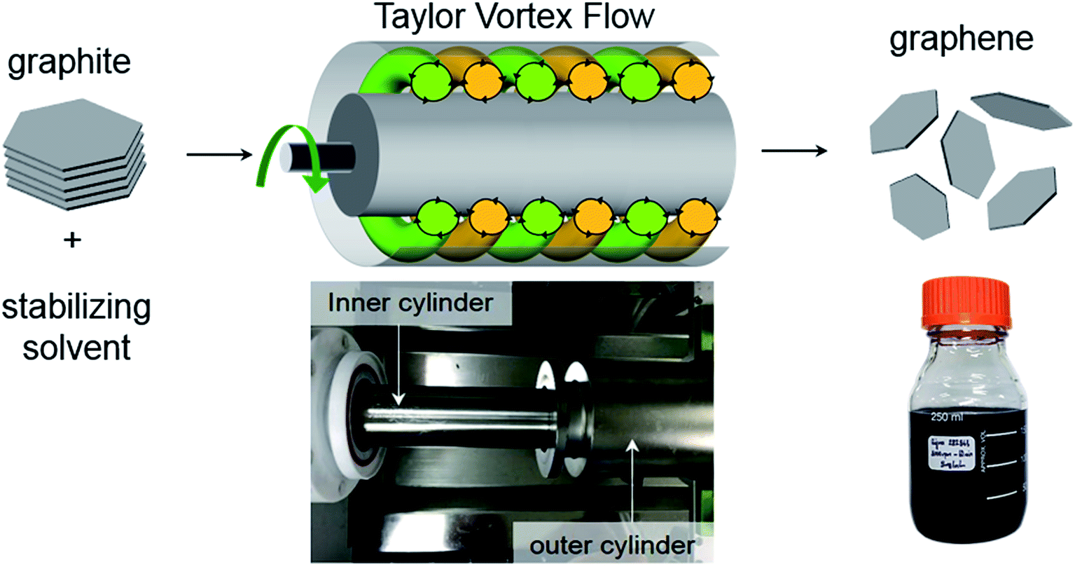 | ||
| Fig. 1 Schematic of the shear-exfoliation of graphite into few-layer graphene by a Taylor Vortex flow. Photographs shows a Taylor–Couette flow reactor and the graphene dispersions produced by shear exfoliation. | ||
A typical experiment involved the shear exfoliation of graphite flakes in NMP at a starting graphite concentration of 5 mg mL−1. The graphite powder with a flake size of 1–10 μm was used in the following experiments because it was more efficiently exfoliated than the larger flakes with a size of 100–200 μm (ESI, Fig. S1†). We also note that NMP was used as a stabilizing solvent because its surface energy is close to that of graphene, facilitating the exfoliation of graphite (ESI, Fig. S2†).12,14 The processing parameters were set as follows: the rotation speed of the inner cylinder was 1500 rpm and the mixing time was 60 min. Afterwards, the resulting dispersion was centrifuged at 1000 rpm for 30 min and the exfoliated flakes in the supernatant were collected for characterization.
Exfoliated graphene flakes
The resulting dispersion was studied by scanning electron microscopy (SEM), transmission electron microscopy (TEM) and atomic force microscopy (AFM) to measure the lateral flake dimension and thickness. The SEM images showed that the exfoliated graphene flakes are relatively thin as compared to the original graphite powders (ESI, Fig. S3†). The TEM images in Fig. 2a shows that thin flakes of different sizes and thicknesses were produced by the shear exfoliation. The lateral flake sizes were in the range of 500 nm to 1500 nm, indicating that the shear exfoliation process fragmented large sheets into smaller sizes. While thin multilayers with some folded region were most commonly observed, very thin layers with smaller sizes (∼500 nm) were also found. An electron diffraction pattern exhibited a typical six-fold symmetric diffraction and a more intense inner set of spots, suggesting the presence of graphene monolayers.11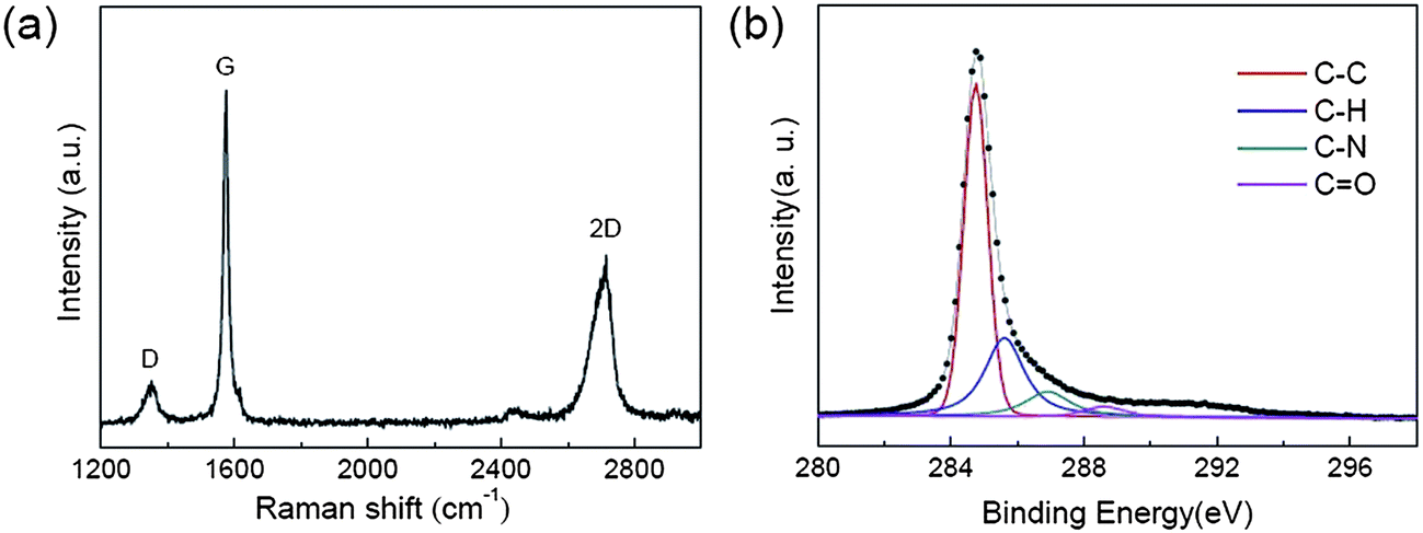 | ||
| Fig. 2 (a) TEM images of exfoliated flakes (inset: electron diffraction pattern), (b) AFM image of the exfoliated flake, where the corresponding height profile displays a height of close to ∼0.6 nm, and histogram of number of layers per flake. | ||
Fig. 2b shows an AFM image of a typical exfoliated flakes. The AFM height profile acquired across the flakes shows that most flakes had a thickness less than 3 nm (Fig. 2b and ESI Fig. S4†), confirming that it was a few-layer graphene. The thinnest flakes measured had an AFM height of close to ∼0.6 nm, which is comparable to the thickness of pristine monolayer graphene on a Si wafer.16 We measured the AFM height of more than 250 exfoliated flakes and estimated the number of monolayers per flake as presented in the histogram in Fig. 2b. This result indicated that ∼90% of the flakes were composed of less than five layers.
The quality of the exfoliated graphene flakes was characterized by Raman spectroscopy and XPS. The Raman spectrum of graphene was characterized by a D-band (1349 cm−1), a G-band (1576 cm−1), and a 2D-band (2706 cm−1), as shown in Fig. 3a.
 | ||
| Fig. 3 (a) Raman and (b) XPS spectra of the exfoliated graphene flakes. | ||
In general, the D-band is associated with the breathing mode of the sp2 carbon atoms and activated by the presence of defects in graphene such as edges, vacancies, or sp3 defects.17–19 The Raman spectrum of thin films produced from graphene dispersion showed a relatively weak D-band with a Raman D/G band intensity ratio (ID/IG) of ∼0.14, indicating a low degree of defects. Considering that the Raman laser beam spot size is larger than most of the graphene flake size, the observed D-band was likely to be dominated by edges rather than basal plane defects.11,14 This suggests that basal plane defects was unlikely introduced during high shear exfoliation of graphite in a turbulent Taylor vortex flow regime.
The XPS was used to probe the presence of defects in the form of oxides and a carbon 1s core level spectrum of the graphene flakes is shown in Fig. 3b. In the spectrum, a dominant peak is observed at ∼285 eV, representing graphitic carbon (C–C). In addition to the C–C peak, the deconvolution of the spectrum disclosed the presence of additional small peaks at higher binding energies. In case of an oxidized graphene, these peaks are assigned to oxides (e.g. C–O and C![[double bond, length as m-dash]](https://www.rsc.org/images/entities/char_e001.gif) O groups) which are covalently bonded to the graphene carbons.4,17 However, given that undamaged basal planes were confirmed by Raman spectroscopy, the small peaks in the XPS spectrum were unlikely to be due to covalently bonded oxides. Alternatively, these peaks may come from the residual solvent (i.e. NMP) within the thin film of graphene flakes.11,14 Therefore, XPS showed no evidence of oxidation, suggesting the high quality of the graphene flakes produced by high shear exfoliation of graphite.
O groups) which are covalently bonded to the graphene carbons.4,17 However, given that undamaged basal planes were confirmed by Raman spectroscopy, the small peaks in the XPS spectrum were unlikely to be due to covalently bonded oxides. Alternatively, these peaks may come from the residual solvent (i.e. NMP) within the thin film of graphene flakes.11,14 Therefore, XPS showed no evidence of oxidation, suggesting the high quality of the graphene flakes produced by high shear exfoliation of graphite.
In order to determine the optimal shear exfoliation conditions, we produced a set of graphene dispersions using a range of processing parameters and evaluated the concentration of graphene produced in each processing condition. The graphene dispersion was centrifuged and the graphene concentration was estimated by measuring the absorbance of the graphene dispersion (ESI, Fig. S5†). The first experiment was carried out by varying the mixing time (t) from 10 min to 120 min, while the other processing parameters remained constant (the rotation speed of inner cylinder was 3000 rpm and the initial graphite concentration was 5 mg mL−1).
Fig. 4a shows that the graphene concentration increased with mixing time following a power law and the time exponents were estimated to be ∼0.36. In the following experiment, we varied the rotation speed of inner cylinder (N) while holding the mixing time constant at 60 min, and measured the graphene concentration. In Fig. 4b, the graphene concentration increased with rotation speed according to a power law. Interestingly, the graphene concentration increased sharply at a rotation speed of ∼1000 rpm, below which the concentration of exfoliated flakes is relatively low. This result suggests that the high local shear rate and high wall shear stress induced by rapidly rotating Taylor–Couette flow are required to produce a larger quantity of graphene flakes.
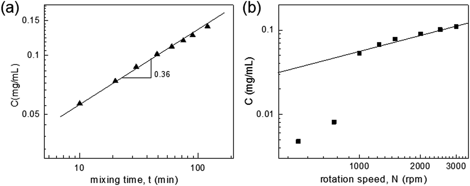 | ||
| Fig. 4 (a) Concentration of graphene flakes plotted as a function of mixing time (t), and (b) graphene concentration plotted against the rotation speed (N) of inner cylinder. | ||
To give more insight into the relationship between shear rate and graphite exfoliation, we performed a computational fluid dynamics (CFD) simulation and compared the result with those obtained from our experiments. With increasing the rotation speed, the Taylor–Couette flow is expected to be sheared strongly enough to undergo a shear instability and become turbulent.20,21 It is known that Taylor vortex flow is formed when the Taylor number (Ta) exceeds the critical value of ∼1700 at which the Taylor instability sets in.22–24

The simulation predicted that the Taylor number as a function of the rotation speed would range from 1 × 10⁶ to 5 × 10⁷ (Ta ∼ 1.1 × 10⁶ for 500 rpm, ∼4.5 × 10⁶ for 1000 rpm, and 4.0 × 10⁷ for 3000 rpm), which is well above the critical value. This indicates that graphene was produced in the turbulent Taylor vortex flow regime. A turbulent Taylor vortex flow could be generated in our reactor at a rotation speed of less than 1000 rpm, but the empirical results showed the existence of a critical rotation speed at which the concentration of exfoliated graphene rapidly increased.
To further understand the shear exfoliation by a turbulent flow, we attempted to predict the local distribution of the shear stress and pressure using CFD simulation as presented in Fig. 5 and ESI Fig. S6.† The simulation predicted that the maximum wall shear stress and pressure would increase with the rotation speed. For example, the maximum wall shear stress increased from 3.98 Pa at 500 rpm to 26.91 Pa at 3000 rpm. At a rotation speed of 1000 rpm, the maximum wall shear stress and pressure were estimated as ∼8 Pa and ∼918 Pa, respectively. Given the empirical data for graphene concentration as a function of the rotation speed, it is possible that these values of the maximum wall shear stress and pressure may be critical to achieve an efficient shear exfoliation of graphite.
 | ||
| Fig. 5 (a) Local distribution of pressure predicted by computational fluid dynamics study, (b) maximum wall shear stress and (c) maximum pressure plotted as a function of the rotation speed of inner cylinder. | ||
We also attempted to optimize the initial graphite concentration (Ci) and estimate the yield of the graphene produced by shear exfoliation.
For this set of experiment, the rotation speed of the inner cylinder was set to 3000 rpm and the graphene concentration was measured while controllably varying the initial graphite concentration from 1 mg mL−1 to 50 mg mL−1.
In Fig. 6, the graphene concentration was found to increase with the initial graphite concentration and the highest graphene concentration achieved was 0.65 mg mL−1 for Ci = 50 mg mL−1. The yield of the exfoliated graphene flakes was greater than 1.1% relative to the total weight of the starting graphite flakes, which is much higher than values reported in the previous studies (ESI, Table S1†).11,12,14 In addition, the yield could further increase up to ∼5% with decreasing initial graphite concentration.
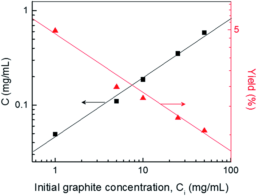 | ||
| Fig. 6 Graphene concentration and yield plotted against the initial graphite concentration. | ||
Conclusions
In summary, we have demonstrated a method for producing high quality graphene by high shear-induced exfoliation of graphite in liquid. This method involved the use of a Taylor–Couette flow reactor, in which a fluid of graphite and solvent was sheared between a rapidly rotating inner cylinder and stationary outer cylinder. We showed that high shear mixing of graphite and solvent in this reactor led to an efficient exfoliation of graphite into few-layer graphene with a very low degree of defects. The present work highlights the importance of highly turbulent Taylor vortex flow to induce high wall shear stress and pressure sufficient to produce graphene flakes at a reasonably high yield. This method provides a simple route for the bulk preparation of high quality graphene dispersion, which may find utility in a range of applications including electronic devices, composite materials, energy storage, and heat generating or dissipation devices. In addition, the described high shear-induced exfoliation scheme can also be used for a range of other layered materials including boron nitride (BN), molybdenum disulphide (MoS2), tungsten disulphide (WS2) and molybdenum (MoSe2).Acknowledgements
This work was supported by the Collaborative Research Program among industry, academia and research institute through the Ministry of Science, ICT and Future Planning (MSIP) and Korea Industrial Technology Association (KOITA) (grant no. KOITA-2014-4).References
- K. S. Novoselov, A. K. Geim, S. V. Morozov, D. Jiang, Y. Zhang, S. V. Dubonos, I. V. Grigorieva and A. A. Firsov, Science, 2004, 306, 666–669 CrossRef CAS PubMed.
- A. K. Geim and K. S. Novoselov, Nat. Mater., 2007, 6, 183–191 CrossRef CAS PubMed.
- K. S. Novoselov, V. I. Fal'ko, L. Colombo, P. R. Gellert, M. G. Schwab and K. Kim, Nature, 2012, 490, 192–200 CrossRef CAS PubMed.
- D. R. Dreyer, S. Park, C. W. Bielawski and R. S. Ruoff, Chem. Soc. Rev., 2010, 39, 228–240 RSC.
- S. Stankovich, D. A. Dikin, R. D. Piner, K. A. Kohlhaas, A. Kleinhammes, Y. Jia, Y. Wu, S. T. Nguyen and R. S. Ruoff, Carbon, 2007, 45, 1558–1565 CrossRef CAS.
- Y. W. Zhu, S. Murali, W. W. Cai, X. S. Li, J. W. Suk, J. R. Potts and R. S. Ruoff, Adv. Mater., 2010, 22, 3906–3924 CrossRef CAS PubMed.
- G. Eda, G. Fanchini and M. Chhowalla, Nat. Nanotechnol., 2008, 3, 270–274 CrossRef CAS PubMed.
- D. Li, M. B. Muller, S. Gilje, R. B. Kaner and G. G. Wallace, Nat. Nanotechnol., 2008, 3, 101–105 CrossRef CAS PubMed.
- W. S. Hummers and R. E. Offeman, J. Am. Chem. Soc., 1958, 80, 1339 CrossRef CAS.
- D. C. Marcano, D. V. Kosynkin, J. M. Berlin, A. Sinitskii, Z. Z. Sun, A. Slesarev, L. B. Alemany, W. Lu and J. M. Tour, ACS Nano, 2010, 4, 4806–4814 CrossRef CAS PubMed.
- Y. Hernandez, V. Nicolosi, M. Lotya, F. M. Blighe, Z. Y. Sun, S. De, I. T. McGovern, B. Holland, M. Byrne, Y. K. Gun'ko, J. J. Boland, P. Niraj, G. Duesberg, S. Krishnamurthy, R. Goodhue, J. Hutchison, V. Scardaci, A. C. Ferrari and J. N. Coleman, Nat. Nanotechnol., 2008, 3, 563–568 CrossRef CAS PubMed.
- M. Lotya, Y. Hernandez, P. J. King, R. J. Smith, V. Nicolosi, L. S. Karlsson, F. M. Blighe, S. De, Z. M. Wang, I. T. McGovern, G. S. Duesberg and J. N. Coleman, J. Am. Chem. Soc., 2009, 131, 3611–3620 CrossRef CAS PubMed.
- V. Nicolosi, M. Chhowalla, M. G. Kanatzidis, M. S. Strano and J. N. Coleman, Science, 2013, 340, 1226419 CrossRef.
- K. R. Paton, E. Varrla, C. Backes, R. J. Smith, U. Khan, A. O'Neill, C. Boland, M. Lotya, O. M. Istrate, P. King, T. Higgins, S. Barwich, P. May, P. Puczkarski, I. Ahmed, M. Moebius, H. Pettersson, E. Long, J. Coelho, S. E. O'Brien, E. K. McGuire, B. M. Sanchez, G. S. Duesberg, N. McEvoy, T. J. Pennycook, C. Downing, A. Crossley, V. Nicolosi and J. N. Coleman, Nat. Mater., 2014, 13, 624–630 CrossRef CAS PubMed.
- X. J. Chen, J. F. Dobson and C. L. Raston, Chem. Commun., 2012, 48, 3703–3705 RSC.
- Z. G. Cheng, Q. Y. Zhou, C. X. Wang, Q. A. Li, C. Wang and Y. Fang, Nano Lett., 2011, 11, 767–771 CrossRef CAS PubMed.
- A. Eckmann, A. Felten, A. Mishchenko, L. Britnell, R. Krupke, K. S. Novoselov and C. Casiraghi, Nano Lett., 2012, 12, 3925–3930 CrossRef CAS PubMed.
- A. C. Ferrari, J. C. Meyer, V. Scardaci, C. Casiraghi, M. Lazzeri, F. Mauri, S. Piscanec, D. Jiang, K. S. Novoselov, S. Roth and A. K. Geim, Phys. Rev. Lett., 2006, 97, 187401 CrossRef CAS PubMed.
- U. Khan, A. O'Neill, M. Lotya, S. De and J. N. Coleman, Small, 2010, 6, 864–871 CrossRef CAS PubMed.
- D. P. M. van Gils, S. G. Huisman, S. Grossmann, C. Sun and D. Lohse, J. Fluid Mech., 2012, 706, 118–149 CrossRef.
- S. G. Huisman, D. P. M. van Gils, S. Grossmann, C. Sun and D. Lohse, Phys. Rev. Lett., 2012, 108, 024501 CrossRef PubMed.
- D. P. Lathrop, J. Fineberg and H. L. Swinney, Phys. Rev. A, 1992, 46, 6390–6405 CrossRef.
- R. Ostilla, R. J. A. M. Stevens, S. Grossmann, R. Verzicco and D. Lohse, J. Fluid Mech., 2013, 719, 14–46 CrossRef.
- J. P. Gollub and H. L. Swinney, Phys. Rev. Lett., 1975, 35, 927–930 CrossRef.
Footnotes |
| † Electronic supplementary information (ESI) available: Additional photographs, SEM and AFM images of graphene sheets produced by high shear-induced exfoliation of graphite. Computational fluid dynamics (CFD) studies for Taylor–Couette flow. See DOI: 10.1039/c5ra22273g |
| ‡ T. S. Tran and S. J. Park equally contributed to this work. |
| This journal is © The Royal Society of Chemistry 2016 |