
 Open Access Article
 This Open Access Article is licensed under a Creative Commons Attribution-Non Commercial 3.0 Unported Licence
Nanosized graphane (C1H1.14)n by hydrogenation of carbon nanofibers by Birch reduction method†
Daniel
Bouša
a,
Jan
Luxa
a,
David
Sedmidubský
a,
Štěpán
Huber
a,
Ondřej
Jankovský
a,
Martin
Pumera
*b and
Zdeněk
Sofer
*a
aDepartment of Inorganic Chemistry, University of Chemistry and Technology Prague, 166 28 Prague 6, Czech Republic. E-mail: zdenek.sofer@vscht.cz; Fax: +420-22431-0422
bDivision of Chemistry & Biological Chemistry, School of Physical and Mathematical Sciences, Nanyang Technological University, Singapore, 637371, Singapore. E-mail: pumera@ntu.edu.sg; Fax: +65-6791-1961
First published on 6th January 2016
Abstract
Graphane, fully hydrogenated graphene with the composition (C1H1)n, has been theoretically predicted but never experimentally realized. Graphane stands out of the variety of heteroatom modified graphene for its well defined structure. Here we show that by employing Birch reduction on graphite nanofibers, one can reach hydrogenation levels close to 100%. We name this material graphane or graphane-like since its composition is relatively close to ideal theoretical stoichiometry C1H1. We systematically study the effect of the size and structure of the starting material and conditions of the synthesis. The morphology and properties of the synthesized graphane-like material are strongly dependent on the structure of the starting material. The extremely highly hydrogenated nanographanes should find applications ranging from nanoelectronics to electrochemistry such as in supercapacitors or electrocatalysts.
Introduction
Graphane – fully hydrogenated graphene – with ideal composition of (C1H1)n was predicted theoretically in 2004.1,2 Despite intensive efforts, graphane has not been synthesized to date. Several preparation methods have been utilized, such as (i) low pressure hydrogen plasma treatment of graphene or graphene oxide3,4 (ii) high pressure/high temperature hydrogenation with molecular H2 (ref. 5) and (iii) wet chemistry route which utilizes Birch reaction.6–8 While low or high pressure hydrogenation leads to hydrogenation levels of 2–10%, the Birch chemical route demonstrated that it is possible to achieve ∼70% hydrogenation or even higher. The highly effective hydrogenation was observed using water as a proton source.9Graphane is an exceptional material in the family of modified graphenes. Hydrogen, together with halogens (note that hydrogen has more properties in common with halogens than with I A elements), create monovalent C–X bonds. This is in contrast to poorly defined graphenes modified with nitrogen,10 oxygen,11,12 sulphur,13 boron14 and other elements.15 Fluorographite, for example, can show levels of fluorination up to about 114% (64 wt% F), giving C1F1.14.
Introduction of hydrogen atoms into graphene sheet can significantly change its electronic and transport properties. Highly conductive semi-metallic graphene is transferred into insulating graphane by hydrogenation. The optical properties of hydrogenated graphene (photoluminescence) were recently investigated in detail.16 Graphane is predicted to have band gap energy of about 3.5 eV. This value can be tuned depending on the degree of graphene hydrogenation.17 Partially hydrogenated graphenes also exhibit ferromagnetic behavior.18 Graphanes and partially hydrogenated graphenes are promising candidates for hydrogen storage due to their ability to undergo a dehydrogenation by annealing.3 Other possible graphane applications include biosensing,19 transistors20 and spintronic devices.21 Even thought, the hydrogenation of large graphene sheets has been explored, no research has been done on fabrication of nanographane. The fabrication of nanosized graphane is of great importance since the particle size limitation shall lead into further opening of the band gap.
In this paper we hydrogenated four different types of graphite nanofibers in the form of stacked nanocones (NF-100-C), stacked plates of hundred nanometers size (NF-600-P), stacked nanosized plates (NF-50-P) and stacked graphite spirals (NF-80-S) by a method based on the Birch reduction to yield nanosized sheets of graphane. Two alkali metals (K and Li) were used for hydrogenation as sources of solvated electrons in liquid ammonia. Water was used as a source of protons. The prepared nanographanes were characterized by a number of analytical techniques. Whereas the maximum hydrogenation rate ∼70% has been reported in literature, here we show that it is possible to reach almost 100% hydrogenation of graphite precursor. The observed results confirmed that we can reach unprecedented hydrogenation levels up to (C1H1.14)n. Such a high hydrogen content is enabled due to small particle size of graphanes, where the number of terminal or edging carbon atoms is not negligible compared to the number of atoms in graphene skeleton. At such high degree of hydrogenation the edges atoms on graphene defect sites within the graphene basal plane also play important role. The structure of nanographanes was refined and we also focused on the careful analysis of thermal stability using STA and TG-MS techniques. A successful preparation and a well defined geometry of highly hydrogenated graphene have a huge potential for the development and construction of novel nanoelectronic and optoelectronic devices.
Experimental
Materials
Carbon nanofibers in the form of stacked nanocones with diameter of 100 nm (termed as NF-100-C) were provided by Sigma-Aldrich, Czech Republic. Graphitized carbon nanofibers in the form of hundred nanometers (200–600 nm) size stacked nanoplates (termed as NF-600-P) were obtained from Nanostructured and Amorphous Materials (Texas, USA). Another type of carbon nanofibers in the form of stacked nanosized plates with diameter ranging from 40 to 50 nm (termed as NF-50-P) was delivered by STREM Chemicals (Newburyport, USA). Carbon nanofibers in the form of stacked nanospirals with diameter ranging from 20 to 80 nm (termed as NF-80-S) were obtained from Gruppo Antolin Ingenieria (Madrid, Spain). Numbers in abbreviations of graphite nanofibers indicate diameter of nanofibers, letters at the end indicate nanofibers shape and element used for intercalation, respectively hydrogenation. Lithium, potassium, and dimethylformamide (DMF) were purchased from Sigma-Aldrich, Czech Republic. Ammonia (99.9995% purity) and argon (99.9996% purity) were delivered by SIAD, Czech Republic. Hydrochloric acid (35%), isopropanol, sodium dihydrogenphosphate and disodium hydrogenphosphate were obtained from Lach-Ner, Czech Republic.Synthetic procedures
Graphite nanofibers (250 mg) and 8.1 g of potassium (or 1.5 g of lithium) were placed into a flask with magnetic stirrer in argon atmosphere. The flask connected to equipment for refluxing of ammonia (cold finger with CO2/acetone bath) was flushed with argon to remove air and ammonia (170 mL) was condensed into the flask using CO2/acetone cooling bath. Mixture of liquid ammonia with alkali metal and graphite nanofibers was refluxed and stirred for 2 h. Subsequently the reaction mixture was cooled in acetone/CO2 bath and 1.8 mL of distilled water was slowly added (during 10 minutes). The mixture was then removed from cooling bath and stirred under reflux for 2 h. Then, an additional amount of 1.8 mL of distilled water was slowly added (over a period of 10 minutes) and the mixture was stirred under reflux for the next 30 min. At the end, 20 mL of distilled water was added slowly (over a period of 30 minutes) to decompose unreacted alkali metals and ammonia was evaporated at room temperature. Finally, solid products were dispersed in distilled water, separated by filtration, redispersed in water acidified with HCl and separated by suction filtration. The product was washed with distilled water/ethanol and dried in vacuum oven at 50 °C for 48 hours. Caution: fast addition of water can lead to violent reaction with alkali metals and explosive reaction.Methods
The morphology was investigated using scanning electron microscope (SEM) equipped with FEG electron source (Tescan Lyra dual beam microscope). Elemental composition of the samples was determined by means of energy dispersive spectroscopy (EDS) analyzer (X-MaxN) with a 20 mm2 SDD detector (Oxford instruments) and AZtecEnergy software. To conduct the measurements, the samples were placed on a carbon conductive tape. All the measurements were carried out with 15 kV acceleration voltage. For the observation in transmission mode STEM detector integrated in electron microscope with 30 kV of applied accelerating voltage was used. Sample dispersion in isopropanol (1 mg mL−1) prepared by ultrasonication and drop casted on 200 mesh TEM grids was used for the observation.Combustible elemental analysis (CHNS-O) was performed using a PE 2400 Series II CHNS/O Analyzer (Perkin Elmer, USA). The instrument was used in CHN operating mode (the most robust and interference-free mode) to convert the sample elements to simple gases (CO2, H2O and N2). The PE 2400 analyzer performed combustion, reduction, homogenization of product gases, separation and detection automatically. An MX5 microbalance (Mettler, Toledo) was used for precise weighing of the samples (1.5–2.5 mg per single sample analysis). Using this procedure, the accuracy of CHN determination is better than 0.30% abs. Internal calibration was performed using an N-fenyl urea.
High resolution X-ray photoelectron spectroscopy (XPS) was performed with ESCAProbeP spectrometer (Omicron Nanotechnology Ltd, Germany) with a monochromatic aluminum X-ray radiation source (1486.7 eV). Wide scan surveys of all elements were performed with subsequent high-resolution scans of the C 1s, O 1s and N 1s. Relative sensitivity factors were used to determine the carbon-to-oxygen ratios (C/O) from the survey spectra. The samples were placed in a conductive carrier made from a high purity silver bar. An electron gun was used to eliminate sample charging during measurement (1–5 V).
An inVia Raman microscope (Renishaw, England) was used for Raman spectroscopy measurements in backscattering geometry with a CCD detector. Nd-YAG laser (532 nm, 50 mW), He–Cd laser (325 nm, 22 mW) with 50× VIS-NIR objective and 40× NUV objective, respectively, were used for the measurement. Instrument calibration was achieved using a silicon reference which gave a peak position at 520 cm−1 and a resolution of less than 1 cm−1. To ensure a sufficiently strong signal and to avoid radiation damage to the samples, the laser power used for these measurements ranged from 0.05 to 5 mW. For the low temperature measurements of Raman spectra, a pulse tube close cycle optical cryostat with base temperature 11 K was used. The sample was mounted on an x–y–z piezoelectric stage with Apiezon N and covered with CaF2 window. In this instance, a 20× magnification long working distance objective optimized for VIS-NIR and NUV was used.
Fourier transform infrared spectroscopy (FTIR) measurements were performed on a NICOLET iS50R FTIR spectrometer (Thermo Scientific, USA). A Diamond ATR crystal and DTGS detector were used for all measurements, which were carried out in the range 3500–500 cm−1. The transmittance FT-IR spectra were measured using KBr pellets.
Characterization by Atomic Force Microscopy (AFM) was performed on NT-MDT Ntegra Spectra (NT-MDT) in tapping mode. Before the measurement, samples were diluted in isopropyl alcohol (0.1 mg mL−1), sonicated for 5 min and drop casted on freshly cleaved mica substrate.
The measurements of ζ-potential were performed on Malvern Zetasizer Nano ZS. Diluted samples (1 mg/10 mL of 50 mM PBS, pH = 7.0) were first sonicated for 5 min and then measured in a folded capillary cell.
Thermal stability towards oxidation was analyzed by simultaneous thermal analysis (STA). The DTA and TG curves were recorded simultaneously on Linseis STA PT1600 apparatus at a heating rate of 10 °C min−1 from ambient temperature to 1000 °C in a dynamic air atmosphere (50 cm3 min−1).
Thermogravimetric analysis-Mass Spectroscopy (TG-MS) was used to analyze thermal behavior of graphanes in inert atmosphere. TG curves and mass spectra were recorded using Setsys Evolution 1750 and Pfeiffer Vacuum Omnistar TM at a heating rate of 10 °C min−1 from ambient temperature to 900 °C in a dynamic argon atmosphere (20 cm3 min−1).
X-ray powder diffraction data were collected at room temperature on Bruker D8 Discoverer powder diffractometer with parafocusing Bragg–Brentano geometry using CuKα radiation (λ = 0.15418 nm, U = 40 kV, I = 40 mA). Data were scanned with an ultrafast detector X'Celerator over the angular range 5–90° (2θ) with a step size of 0.019° (2θ). Data evaluation was performed in the software package EVA.
Electrochemical characterization was performed by cyclic voltammetry using an Interface 1000 potentiostat (Gamry, USA) with a three electrode set-up. The glassy carbon working electrode (GC), platinum auxiliary electrode (Pt) and Ag/AgCl reference electrode were obtained from Gamry (USA). For the cyclovoltammetric measurements, graphane was dispersed in DMF (1 mg mL−1) and 1.5 μL was evaporated on the glass carbon working electrode. All potentials, stated in the following section, were measured against the Ag/AgCl reference electrode. To measure the inherent electrochemistry, a phosphate buffer solution (PBS, 50 mM, pH = 7.2) was used as the supporting electrolyte. The heterogeneous electron transfer (HET) rate was measured using a 10 mM K4[Fe(CN)6]/K3[Fe(CN)6] redox probe, with a 50 mM PBS solution as the supporting electrolyte. The capacitance measurement was performed using drop casted samples on glass carbon electrode (1.5 μL, 1 mg mL−1) in the potential range of −0.2 V to +0.5 V using the scan rate 25 mV s−1 to 400 mV s−1. PBS (pH = 7.2, c = 0.05 M) was used as a supporting electrolyte.
Results and discussion
We studied the efficiency of Birch reduction on several nanocarbon fibers. Four different types of carbon nanofibers (NF-100-C, NF-600-P, NF-50-P and NF-80-S; for abbreviations meanings see Materials in Experimental section) were used for the hydrogenation in order to investigate the influence of the size of graphene platelets. We abbreviate samples in this paper according to the type of carbon nanofiber and alkali metal used during hydrogenation as: NF-100-C, NF-600-P, NF-50-P and NF-80-S with “/K” or “/Li” depending on alkali metal used for synthesis. Extensive materials characterization involving scanning electron microscopy (SEM), scanning transmission electron microscopy (STEM), atomic force microscopy (AFM), Fourier-transform infrared spectroscopy (FTIR), combustible elemental analysis, X-ray photoelectron spectroscopy (XPS), Raman spectroscopy, zeta potential measurement and electrochemical characterization was performed to elucidate the nature of the prepared samples.Briefly, the hydrogenation was carried out in liquid ammonia. 250 mg of graphite nanofibers were reacted in liquid ammonia with 21 mmol of K (or Li). The hydrogenation was subsequently performed by slow addition of water (1.8 mL) after 2 hours and 4 hours (1.8 mL). Finally, after 30 minutes the unreacted alkali metal was decomposed by water addition and ammonia was evaporated. The formed graphane nanostructures were separated by suction filtration and repeatedly washed with deionized water.
Subsequently, we investigated the rate of hydrogenation by combustible elemental analysis. The amount of hydrogen introduced was as high as 44.93 at% for NF-100-C/K (see Table 1). The lowest content of hydrogen was reached for NF-50-P samples, irrespective of the alkali metal used. It is important to mention that some amount of the measured hydrogen can originate from oxygen containing groups such as hydroxyls and carbonyls. If we assume a 1![[thin space (1/6-em)]](https://www.rsc.org/images/entities/char_2009.gif) :1 stoichiometry of oxygen to hydrogen in the form of hydroxyl groups, the remaining hydrogen must originate from C–H bonds themselves. Thus, if we subtract the oxygen atomic content from hydrogen, we obtain the atomic content of hydrogen bonded directly to graphene backbone. These results are summarized in Table 1. Additionally, the extreme assumption of 1:1 stoichiometry of oxygen to hydrogen is highly unlikely as the materials contain other functional groups such as carboxyls (2:1 stoichiometry of O:H) and carbonyls (1:0 stoichiometry of O:H). Thus, the results in Table 1, marked as H–O at%, represent a minimum content of C–H bonds formed during hydrogenation and the real value is expected to be significantly higher. Graphane, fully hydrogenated graphene, has the C:H ratio equal to 1, therefore we calculate C:H ratio in our samples to show the extent of carbon materials hydrogenation (Table 1). Samples denoted as NF-100-C/K and NF-600-P/K exhibit C:H ratio close to 1, which indicates a complete hydrogenation of graphene backbone with the composition of C1H1.01O0.21 and C1H1.02O0.35, respectively. Other samples exhibit much higher C:H ratios, which can indicate that the hydrogenation of graphene backbone does not reach completion. The concentration of hydrogen has a significant effect on the color of synthesized material, where graphane with lowest hydrogen concentration is dark brown (NF-50-P), while the material with the highest concentration of hydrogen is light brown (NF-100-C). The color of graphane samples is closely related to the chemical composition, where the most hydrogenated materials have light brown color. This is clearly visible on Fig. 1.
:1 stoichiometry of oxygen to hydrogen in the form of hydroxyl groups, the remaining hydrogen must originate from C–H bonds themselves. Thus, if we subtract the oxygen atomic content from hydrogen, we obtain the atomic content of hydrogen bonded directly to graphene backbone. These results are summarized in Table 1. Additionally, the extreme assumption of 1:1 stoichiometry of oxygen to hydrogen is highly unlikely as the materials contain other functional groups such as carboxyls (2:1 stoichiometry of O:H) and carbonyls (1:0 stoichiometry of O:H). Thus, the results in Table 1, marked as H–O at%, represent a minimum content of C–H bonds formed during hydrogenation and the real value is expected to be significantly higher. Graphane, fully hydrogenated graphene, has the C:H ratio equal to 1, therefore we calculate C:H ratio in our samples to show the extent of carbon materials hydrogenation (Table 1). Samples denoted as NF-100-C/K and NF-600-P/K exhibit C:H ratio close to 1, which indicates a complete hydrogenation of graphene backbone with the composition of C1H1.01O0.21 and C1H1.02O0.35, respectively. Other samples exhibit much higher C:H ratios, which can indicate that the hydrogenation of graphene backbone does not reach completion. The concentration of hydrogen has a significant effect on the color of synthesized material, where graphane with lowest hydrogen concentration is dark brown (NF-50-P), while the material with the highest concentration of hydrogen is light brown (NF-100-C). The color of graphane samples is closely related to the chemical composition, where the most hydrogenated materials have light brown color. This is clearly visible on Fig. 1.
| Sample | C at% | O at% | H at% | N at% | H–O at% | Composition |
|---|---|---|---|---|---|---|
| NF-80-S/K | 40.62 | 15.19 | 42.86 | 1.33 | 27.67 | C1H1.06O0.37 |
| NF-80-S/Li | 46.94 | 12.32 | 39.81 | 0.93 | 27.49 | C1H0.85O0.26 |
| NF-50-P/K | 75.03 | 2.41 | 22.43 | 0.13 | 20.02 | C1H0.30O0.03 |
| NF-50-P/Li | 67.23 | 3.11 | 29.54 | 0.12 | 26.43 | C1H0.44O0.05 |
| NF-600-P/K | 41.24 | 14.36 | 42.19 | 2.21 | 27.83 | C1H1.02O0.35 |
| NF-600-P/Li | 37.13 | 19.14 | 42.18 | 1.55 | 23.06 | C1H1.14O0.52 |
| NF-100-C/K | 44.61 | 9.34 | 44.93 | 1.12 | 35.60 | C1H1.01O0.21 |
| NF-100-C/Li | 47.68 | 9.63 | 41.48 | 0.85 | 32.21 | C1H0.88O0.20 |
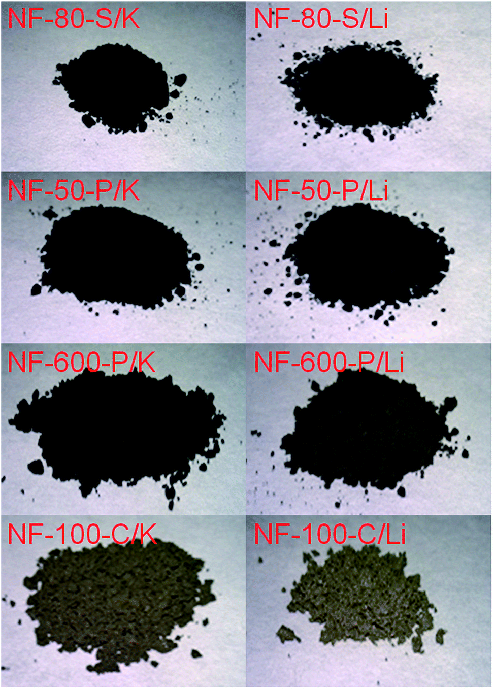 | ||
| Fig. 1 The images of hydrogenated graphene nanofibers. | ||
The surface morphologies of the graphane samples were studied by scanning electron microscopy (SEM). Graphane surface characteristics at various magnifications are shown in Fig. 2. Significant differences can be observed between the individual samples. The SEM images of starting graphite nanofibers are shown in ESI (Fig. SI1†). The NF-50-P samples prepared either by hydrogenation with Li or K have very fine microstructure composed into larger aggregates. This indicates a high degree of exfoliation and subsequent hydrogenation when small platelet graphane nanoparticles form large grains. NF-80-S sample composed from short individual nanofibers agglomerated to larger particles. The fibrous structure can be seen most clearly on the NF-100-C sample treated with both alkali metals, potassium or lithium. NF-600-P sample exhibits a worm like structure composed of individual graphane platelets. These originate from graphite fibers of larger size which can be seen on starting materials revealing a relatively broad distribution of graphite fibers diameter.
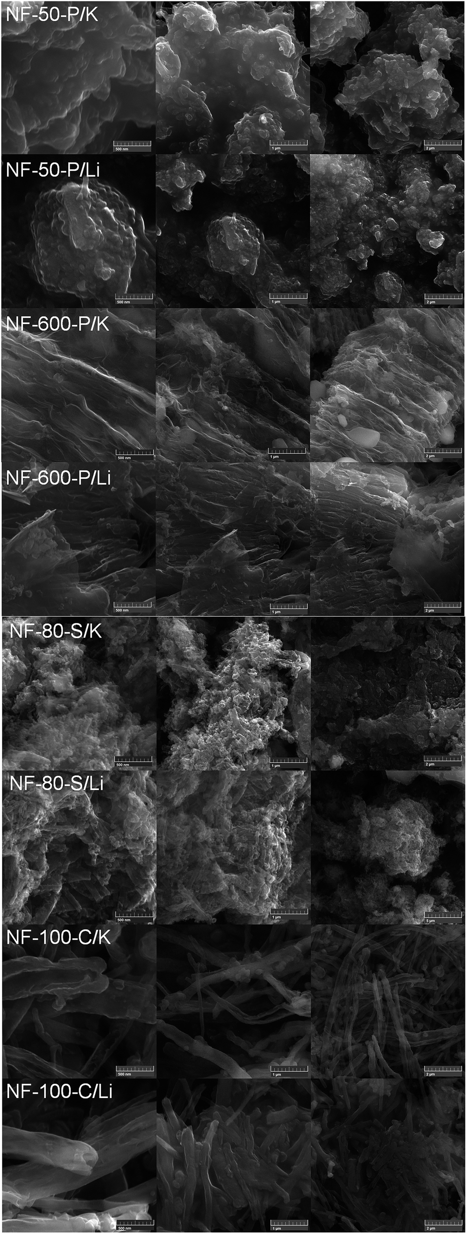 | ||
| Fig. 2 The SEM images of hydrogenated graphite nanofibers. The scale bar corresponds to 0.5 μm (left column), 1 μm (middle column) and 2 μm (right column). | ||
The morphology of nanostructured graphene can be seen more clearly on STEM images (Fig. 3). NF-50-P forms very small particles resulting from small diameter of starting graphite nanofibers. Since small fragments with fibrous structure are visible on the images, some parts of the material are likely not completely exfoliated during hydrogenation procedure. This can also explain a relatively low concentration of hydrogen within the samples. NF-600-P/Li and NF-600-P/K samples are composed of typical platelets and also fibrous structures originating from broad distribution of sizes of starting graphite nanofibers. Wrinkled structure of graphane fibers indicates their partial opening. The NF-80-S samples form short tube like structure derived from the structure of starting graphite composed of spiral nanofibers. Moreover, stacked conical structures can be clearly seen on NF-100-C samples.
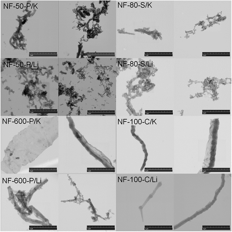 | ||
| Fig. 3 The STEM images of hydrogenated graphene nanofibers. The scale bar correspond to 1 μm (left column) and 2 μm (right column). | ||
In order to further investigate the morphology of the hydrogenated carbon nanofiber samples, the materials were examined using AFM. Fig. 4 shows typical AFM micrographs of the hydrogenated carbon nanofibers prepared by Birch reduction using potassium. AFM images suggest that carbon nanofiber microstructure was disrupted during hydrogenation process and we can see individual nanostructures corresponding to single layer graphane (1.2–1.6 nm) in the case of samples NF-80-S/K, NF-50-P/K and NF-600-P/K. The NF-80-S/K sample exhibits not only etching of the individual graphane sheets, but also a high degree of fragmentation. This is also documented by the results of FT-IR spectroscopy revealing a twining of C–H vibration band. This is further discussed in the following paragraph. In the case of NF-100-C/K the thickness corresponds to a double layer material since we observed a complete graphane cone placed on the mica substrate. The observed structure shows a high degree of site etching during Birch reduction of graphite nanofibers. Since the nanofibers used for synthesis contain a relatively broad distribution of fiber sizes we can also observe bigger plates or graphane nanoplates aggregates.
 | ||
| Fig. 4 The AFM images of graphane nanoplates from samples exfoliated using potassium ((a) NF-80-S/K; (b) NF-50-P/K; (c) NF-600-P/K; (d) NF-100-C/K). | ||
With the aim to determine whether the hydrogenation of carbon nanofibers materials by the Birch reduction was successful, we employed FT-IR spectroscopy (Fig. 5) to identify the presence of chemically bonded hydrogen. Several differences are in evidence on the FT-IR spectra depending not only on the structure of the starting graphite nanofibers, but also on the alkali metal used. In general, the Birch reduction reaction proceeds more violently with significantly more reactive potassium compared to lithium. This can be demonstrated on the structure of C–H bonds stretching present at 2800–3000 cm−1. In general we observe main C–H bond stretching band at 2850 cm−1, however the use of potassium in hydrogenation procedure led to its twinning and we can observe an additional C–H stretching bond at 2920 cm−1. Since higher degree of disorder and structure partial etching (as observed by AFM, SEM and STEM) led to a higher concentration of CH2 groups on the edges, we observed this additional stretching band dominantly on the samples hydrogenated with potassium. The overtones of C–H stretching can be observed around 1450 cm−1 as weak bands. In addition we can associate vibration bands in the range of 900–600 cm−1 with an in-plane C–H bending and out-of-plane C–H bending. These bands provide a definitive proof of successful hydrogenation of carbon nanofibers.22,23 Infrared spectra exhibit also other bands, which can be assigned to O–H vibrations from hydroxyl and carboxyl's groups (3300 cm−1 to 3500 cm−1), C![[double bond, length as m-dash]](https://www.rsc.org/images/entities/char_e001.gif) O stretching (1650 cm−1), aromatic CC stretching (1580 cm−1) and a set of peaks arising from C–C vibrations (1220 cm−1).24,25 The in-plane O–H bending can be seen in the range of 1300–1400 cm−1 and the corresponding stretching of C–O bonds in the range of 1100–1250 cm−1. The presence of various oxygen functionalities in the form of C–O and also CO bonds is due to extremely high reactivity of alkali metal intermediate product with graphite nanofibers. High affinity towards oxygen and carbon dioxide led to the formation of oxygen functionalities during water quenching procedure. The presence of oxygen functionalities also indicates a higher concentration of oxygen observed by elemental combustion analysis and high resolution XPS spectra of C 1s peak discussed in the following paragraphs.
O stretching (1650 cm−1), aromatic CC stretching (1580 cm−1) and a set of peaks arising from C–C vibrations (1220 cm−1).24,25 The in-plane O–H bending can be seen in the range of 1300–1400 cm−1 and the corresponding stretching of C–O bonds in the range of 1100–1250 cm−1. The presence of various oxygen functionalities in the form of C–O and also CO bonds is due to extremely high reactivity of alkali metal intermediate product with graphite nanofibers. High affinity towards oxygen and carbon dioxide led to the formation of oxygen functionalities during water quenching procedure. The presence of oxygen functionalities also indicates a higher concentration of oxygen observed by elemental combustion analysis and high resolution XPS spectra of C 1s peak discussed in the following paragraphs.
 | ||
| Fig. 5 The FT-IR spectra of hydrogenated graphite nanofibers. | ||
The XPS spectroscopy was used in order to get a deeper insight in the composition of the prepared materials which was obtained from survey spectra (see Fig. 6). The resulting concentrations of carbon and oxygen are summarized in Table 2. Two main peaks corresponding to C 1s at 285 eV and O 1s at 583 eV can be seen in the spectra. In general the higher C/O ratio was observed in samples prepared with lithium. The presence of oxygen in the samples indicates a high affinity of the synthesized materials towards formation of oxygen functional groups during synthesis procedure. The similar behavior was observed by FT-IR spectroscopy where the presence of oxygen functionalities was observed. The relative peak intensities of the C 1s to O 1s peaks (abbreviated as C/O ratio) provide a good comparison of oxygen content in different graphane samples (see Table 2). The highest C/O ratio was observed for NF-80-S carbon nanospirals, no matter of what alkali metal was used. On the other side, the lowest C/O ratio was observed for NF-50-P/Li. The NF-600-P and NF-100-C samples also exhibit low C/O ratio. Traces of fluorine were detected in NF-50-P/K sample which can be attributed to the material contamination during measurement or synthesis.
 | ||
| Fig. 6 The XPS survey spectra of hydrogenated graphite nanofibers. | ||
| Sample | At% C | At% O | C/O ratio |
|---|---|---|---|
| NF-80-S/K | 94.1 | 5.9 | 15.89 |
| NF-80-S/Li | 92.9 | 7.1 | 13.10 |
| NF-50-P/K | 89.4 | 8.6 | 10.41 |
| NF-50-P/Li | 80.9 | 19.1 | 4.23 |
| NF-600-P/K | 84.3 | 15.7 | 5.57 |
| NF-600-P/Li | 88.9 | 11.1 | 7.91 |
| NF-100-C/K | 88.7 | 11.3 | 7.86 |
| NF-100-C/Li | 84.2 | 15.8 | 5.33 |
For identification of various oxygen containing groups, we measured high-resolution XPS spectra of the C 1s peak (Fig. 7). All spectra showed a peak centered at 284.5 eV originating from sp2 hybridized carbon atoms (CC), however its intensity is strongly dependent on the degree of hydrogenation and also on the concentration of remaining oxygen functionalities. The states attributed to C–H bonds constitute a typical feature located at 285.5 eV reflecting the degree of hydrogenation. It should be mentioned that C–H bonds have a similar chemical shift to C–C bonds of sp3 hybridized carbon and it is therefore difficult to distinguish the two from XPS measurement alone. The oxygen functionalities are located at higher energies, alcohol and ether groups (C–O) at 286.7 eV, ketone groups (CO) at 288.2 eV, carboxylic acid/ester groups (O–CO) at 289.5 eV and a small contributions of the π–π* interaction with graphane skeleton at 290.8 eV. The deconvolution of C 1s peak was performed and the relative abundances of each bond type are given in Table 3. The highest population of C–H bonds was observed for samples with the highest concentration of hydrogen based on elemental combustion analysis and the results show the evidence of successful hydrogenation. The presence of oxygen functionalities documented by high resolution XPS spectra is also in agreement with elemental combustion analysis and FT-IR spectroscopy where several oxygen functionalities involving C–O and CO bands were observed.
 | ||
| Fig. 7 The high resolution XPS spectra of C 1s peak with deconvolution of individual components. | ||
| Sample | CC, % |
C–C/C–H, % | C–O, % | CO, % |
O–CO, % |
π–π*, % |
|---|---|---|---|---|---|---|
| NF-80-S/K | 0.6 | 30.6 | 9.9 | 29.6 | 28.2 | 1.1 |
| NF-80-S/Li | 17.9 | 34.3 | 18.8 | 19.2 | 7.2 | 2.6 |
| NF-50-P/K | 64.6 | 21.5 | 4.4 | 5.3 | 2.2 | 2.0 |
| NF-50-P/Li | 38.1 | 40.8 | 10.3 | 3.5 | 6.2 | 1.1 |
| NF-600-P/K | 30.4 | 53.8 | 11.6 | 0.1 | 1.3 | 2.8 |
| NF-600-P/Li | 28.0 | 40.9 | 21.0 | 4.4 | 3.5 | 2.2 |
| NF-100-C/K | 12.4 | 38.4 | 17.8 | 11.0 | 18.3 | 2.1 |
| NF-100-C/Li | 6.0 | 51.8 | 33.4 | 3.9 | 4.6 | 0.3 |
In the next step we employed Raman spectroscopy to gain further insight into the hydrogenated graphenes structures and their defect densities (Fig. 8). Most of the samples exhibit spectra typical of graphene materials in which the G (graphitic) band at about 1560 cm−1, corresponds to two fold degenerate E2g mode characteristic of pristine C-sp2 bonded graphene lattices26,27 and second D (disorder) band at 1350 cm−1 arises from A1g breathing mode and occurs only in the presence of defects invoking sp3-type bonding of carbon atoms.28,29 NF-50-P samples also exhibit broad peaks related to the 2D phonon mode (located around 2650 cm−1) and D + D′ phonon mode (located around 2880 cm−1). Defect densities of various graphene materials can be compared by calculating the relative D to G band intensities (abbreviated as ID/IG ratio). Higher ratios indicate an increased disorder in the graphane structure. A comparison of the ID/IG ratios is summarized in Table 4. Intensive luminescence background associated with high degree of graphene hydrogenation related to band-gap-opening can be seen in the Raman spectra. The luminescence background increased the difficulties to calculate exact ID/IG ratio. In general the starting graphite nanofibers exhibit lower ID/IG ratio compared to hydrogenated samples. This clearly indicates an increase of sp3 hybridized carbon atoms as well as a presence of defects induced by hydrogenation procedure. The only exception exhibit NF-50-P sample, where the origin of high ID/IG ratio can be explained by presence of amorphous carbon in graphite nanofibers used for hydrogenation. The background luminescence of the material is closely related to the concentration of C–H bonds and can be correlated with hydrogen concentration. The lowest background luminescence intensity is observed on NF-50-P samples with the lowest degree of hydrogenation. High degree of hydrogenation typical for NF-600-P/Li and NF-100-C/Li samples led to a complete overlap of D and G peaks due to strong photoluminescence of the sample. The presence of photoluminescence may be attributed to band gap splitting by the covalently bonded hydrogen in hydrogenated carbon nanofibers. It was found that the band gap energy Eg in graphane is dependent on the degree of hydrogenation29 and a strong luminescence was reported for graphane with high hydrogen content.30 In order to obtain Raman spectra from NF-600-P/Li sample with strong photoluminescence background, low temperature Raman spectra were measured down to 12 K (Fig. 9). The temperature lowering led to an enhancement of both D and G phonon mode intensities which can be clearly distinguished and separated below 50 K. The ID/IG ratio of 0.99 for NF-600-P/Li was found at 12 K. In addition we also performed Raman spectroscopy measurements using He–Cd laser (325 nm) in order to get the data from spectral region with lower luminescence background. The results are shown in ESI (Fig. SI2†). However, in the case of UV light excitation we observed a significantly different ID/IG ratio compared to 532 nm laser. This originates from significantly different sensitivity towards D and G type modes in the UV range. Such effect was observed on various types of carbon nanomaterials like carbon nanotubes and nanodiamonds.31,32
 | ||
| Fig. 8 The Raman spectra of hydrogenated graphite nanofibers. Raman spectra of starting graphite nanofibers are also shown for comparison. Strong luminescence background is observed on highly hydrogenated samples. | ||
| Sample | I D/IG |
|---|---|
| NF-80-S/K | 1.14 |
| NF-80-S/Li | 0.83 |
| NF-50-P/K | 1.23 |
| NF-50-P/Li | 1.45 |
| NF-600-P/K | 1.15 |
| NF-600-P/Li | 1.14 |
| NF-100-C/K | 0.94 |
| NF-100-C/Li | 1.00 |
 | ||
| Fig. 9 The Raman spectra of NF-600-P/Li sample measured in the range of 300 K to 12 K. | ||
The observed photoluminescence during the measurement of Raman spectra encouraged us to acquire the photoluminescence spectra of all samples as illustrated in Fig. 10. Almost all samples exhibit photoluminescence with a maximum at the edge of NIR region around 790 nm. Another maximum has been observed at 630 nm in the region of red color. Only NF-600-P/Li sample exhibited a different photoluminescence spectrum with two maxima at 705 nm and 625 nm. The photoluminescence of NF-600-P/Li sample is also about twice more intensive compared to other samples. This can originate from the highest C/H ratio obtained by elemental combustion analysis.
 | ||
| Fig. 10 The photoluminescence spectra of hydrogenated graphite nanofibers. He–Cd laser was used for the excitation (325 nm, 2.2 mW). | ||
Thermal stability of the synthesized graphanes as well as starting materials was tested by STA in a dynamic air atmosphere (Fig. SI3†). Generally the oxidation of graphanes started at much lower temperatures compared to the starting materials. The highest difference was observed for the highly hydrogenated samples. While NF-600-P started to oxidize at 604 °C, the NF-600-P/Li started to decompose already at 298 °C. Such a shift suggests a significantly higher reactivity compared to graphite nanofibers used for hydrogenation. Also the shape of DTA signal was different for the starting materials and the highly hydrogenated graphanes. While for all starting materials only one local maximum was found, highly hydrogenated graphanes had two maxima: the onset temperature of the first thermal effect was detected at 250–300 °C, whereas the second thermal effect (oxidation) was found in the range 350–450 °C. The first thermal effect is related to the decomposition of graphane as well as the remaining oxygen functionalities. The second peak is related to complete oxidation of the formed graphene to CO2. The thermal stability is also related to the degree of hydrogenation, where the highest thermal stability was observed on samples NF-50-P/K and NF-50-P/Li with the lowest degree of hydrogenation.
In the next step thermal stability was probed using thermogravimetric analysis in an inert atmosphere coupled with the MS analysis of the released gaseous products during the heating. The results of TG analysis are shown in Fig. 11. The TG curves revealed similar trends at low temperatures. Graphanes were stable up to ∼150 °C, above this temperature gaseous products such as hydrogen, water and carbon dioxide were formed. Mass spectra observed for hydrogen are shown in Fig. 12. The evolution of hydrogen started at approx. 250 °C for all samples. This clearly indicates a successful synthesis of highly hydrogenated graphene which undergoes a dehydrogenation at elevated temperatures under the release of gaseous H2. At ∼650 °C the amount of hydrogen started to decrease suggesting the completion of dehydrogenation process. These results confirmed a successful synthesis of highly hydrogenated graphanes. The mass spectra for water and carbon dioxide are shown in ESI (Fig. SI4†). While water is evolved at lower temperatures, carbon dioxide is the predominant species at higher temperatures. Moreover low concentrations of benzene (m/z = 78) and other organic compounds were detected during the thermal treatment in some samples33,34 associated with a partial decomposition of graphene skeleton during the heating.
 | ||
| Fig. 11 Thermogravimetric signal for graphanes measured in a dynamic argon atmosphere. | ||
 | ||
| Fig. 12 The temperature dependence of relative intensity of the evolved hydrogen from graphanes. | ||
The hydrogenated graphenes were further characterized by X-ray diffraction. The results are shown on Fig. 13. A significant shift of (002) reflection from 26.4° 2θ corresponding to interlayer spacing 0.337–0.339 nm to 18.4–19.8° 2θ was observed after hydrogenation which corresponds to interlayer spacing about 0.45–0.48 nm. This is already very close to the theoretical value of 0.487 nm for pure graphane derived from the covalent radii for hydrogen (RH = 0.030 nm) and carbon atom (RC = 0.077 nm) as well as van der Waals radius of hydrogen atom (RH(vdW) = 0.111 nm)35 using the equation:
| d = 2RH + 2RC + 2RH(vdW) + 2RCcos(π − 109.5°) |
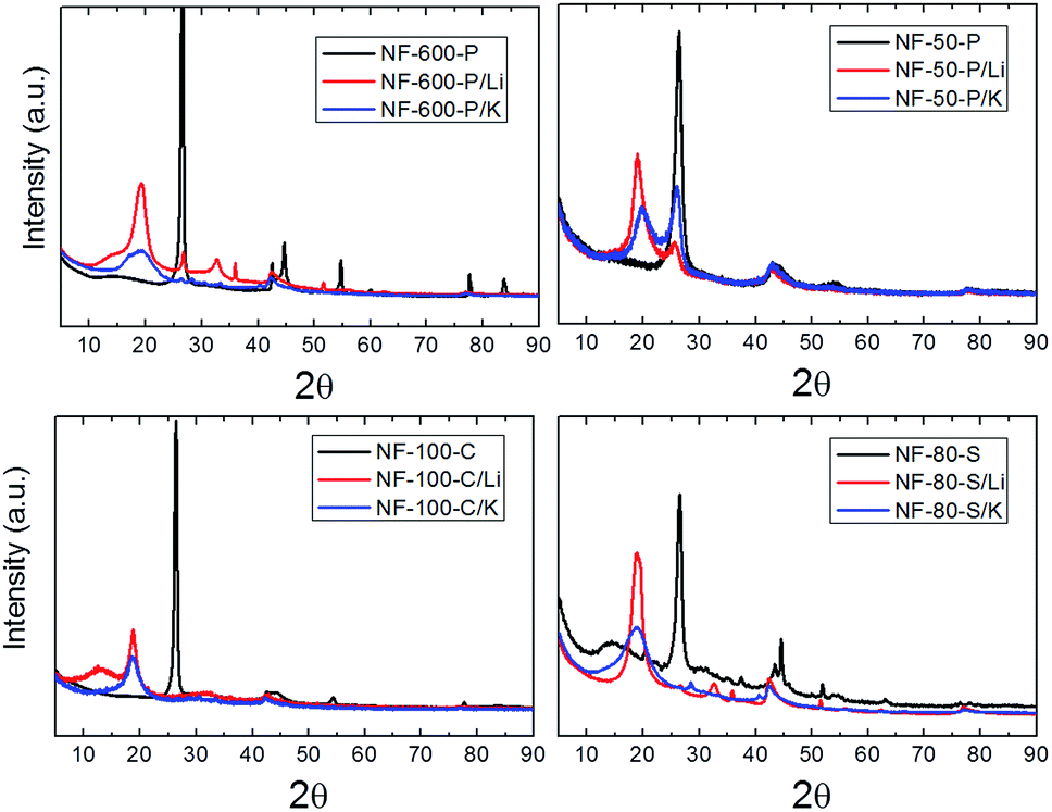 | ||
| Fig. 13 X-ray diffraction patterns of the starting materials in comparison with the hydrogenated graphenes. | ||
The scheme of graphane structure with the corresponding interlayer spacing is shown on Fig. 14. The lower degree of hydrogenation is clearly visible on samples NF-50-P/Li and NF-50-P/K with the lowest concentration of hydrogen, where the twinning of (002) reflection can be seen. This indicates a coexistence of hydrogenated and non-hydrogenated parts in graphene. The broadening of (002) reflection points to a high degree of exfoliation. Using the Scherrer formula and the calculated interlayer spacing we can estimate the average number of 2–6 layers with the exception of NF-100-C/Li with the average of 10 layers.36 The samples NF-80-S/Li and NF-600-P/Li contain small amounts of exfoliation by-products, namely LiOH. Due to highly hydrophobic properties of the hydrogenated graphene a complete removal of impurities is extremely difficult even when using hydrochloric acid or acetic acid at elevated temperatures or under sonication.
 | ||
| Fig. 14 Schematic drawing of graphane structure. | ||
High degree of hydrogenation led to intensive hydrophobic properties demonstrated by measurement of ζ–potential. All samples exhibit ζ–potential close to 0 mV with only slight differences related to the presence of oxygen functional groups introduced during hydrogenation procedure. The measurement was performed on dispersions of nanographanes in 0.05 M PBS with pH = 7.0 and the results are summarized in Fig. SI5.† This indicated that hydrogenation of graphene is accompanied with a significant reduction of ζ-potential and the synthesized material exhibits highly hydrophobic properties.
Finally the electrochemical properties were investigated using measurement of inherent electrochemistry in 0.05 M PBS (pH = 7.2) and the peak-to-peak separation corresponding to heterogeneous electron transfer (HET) rate was investigated using [Fe(CN)6]3−/4− redox probe. The inherent electrochemistry of nanographanes is shown in ESI (Fig. SI6†). No significant reduction signal can be observed in the range of 0 V to −1.5 V. All samples hydrogenated by lithium or potassium exhibit almost identical electrochemical behaviour in both anodic and cathodic scan. These observations indicate that only minor amount of reducible groups is present. However this effect can be also associated with low conductivity of hydrogenated graphene due to the band gap opening. The estimation of HET rate represented by peak-to-peak separation value was performed using [Fe(CN)6]3−/4− redox probe in 50 mM PBS supporting electrolyte (pH = 7.2). The cyclic voltammograms are shown in Fig. 15 and the obtained values of peak-to-peak separation are summarized in Table 5. In general, higher degree of hydrogenation led to reduction of peak-to-peak separation (corresponding to HET rate). This effect is the highest for samples NF-100-C/K, NF-100-C/Li and NF-600-P/Li with peak-to-peak separation value 247 mV, 159 mV and 146 mV, respectively. All other hydrogenated samples have the peak-to-peak value comparable (ΔE = 131–138 mV) with glass carbon electrode (ΔE = 137 mV). However, the samples with the lowest concentration of hydrogen have slightly lower values of peak-to-peak separation (ΔE = 131–133 mV).
 | ||
| Fig. 15 The cyclic voltammograms of hydrogenated graphite nanofibers. [Fe(CN)6]3−/4− was used as a redox probe (c = 0.01 M). PBS (c = 0.05 M, pH = 7.2) was used as a supporting electrolyte. | ||
| Sample | E ox (mV) | E red (mV) | ΔE (mV) |
|---|---|---|---|
| NF-80-S/K | 358 | 220 | 138 |
| NF-80-S/Li | 353 | 222 | 131 |
| NF-50-P/K | 353 | 218 | 135 |
| NF-50-P/Li | 353 | 221 | 133 |
| NF-600-P/K | 357 | 219 | 138 |
| NF-600-P/Li | 359 | 215 | 146 |
| NF-100-C/K | 417 | 170 | 247 |
| NF-100-C/Li | 364 | 205 | 159 |
| GC | 358 | 221 | 137 |
In addition we performed the capacitance measurement using cyclic voltammetry in phosphate buffer solution. The results of capacitance measurement are shown in Fig. 16 and the corresponding cyclo-voltammograms are shown in ESI (Fig. SI7†). With the exception of samples NF-50-P/Li and NF-50-P/K all samples exhibit the capacitance about 1 F g−1. The samples synthesized from NF-50-P graphitic nanofibers have significantly higher capacitance in the range of 7–8 F g−1.
 | ||
| Fig. 16 The capacitance of hydrogenated graphenes measured by cyclic voltammetry. PBS (c = 0.05 M, pH = 7.2) was used as a supporting electrolyte. | ||
Conclusion
We demonstrated the synthesis of graphane (and highly hydrogenated graphenes) with a composition of up to (C1H1.14)n and a controlled size and structure. Graphane nanomaterials were synthesized in the form of nanoplates with various dimension, nanocones and nanospirals. Nanostructured graphane exhibits intensive luminescence in the visible range of spectra and it also shows highly hydrophobic behavior. The presence of C–H bond was indicated and the hydrogen quantification was performed by various methods including FT-IR spectroscopy, XPS, XRD and elemental combustion analysis. The evolution of hydrogen at temperatures above 200 °C was observed using STA-MS analysis. The electrochemical properties are closely related to the degree of hydrogenation where the samples with the highest concentration of hydrogen exhibit the highest peak-to-peak separation. This originates form low conductivity of graphane, which belongs to wide band-gap semiconductors. The capacitance of synthesized nanographanes is strongly dependent of the structure of starting graphite nanofibers and can reach up to 8 F g−1.Acknowledgements
The project was supported by Czech Science Foundation (GACR No 15-09001S) and by Specific university research (MSMT No. 20/2016). M. P. acknowledges a Tier 2 grant (MOE2013-T2-1-056; ARC 35/13) from the Ministry of Education, Singapore.Notes and references
- M. H. F. Sluiter and Y. Kawazoe, Phys. Rev. B: Condens. Matter Mater. Phys., 2003, 68, 085410 CrossRef.
- J. O. Sofo, A. S. Chaudhari and G. D. Barber, Phys. Rev. B: Condens. Matter Mater. Phys., 2007, 75, 153401 CrossRef.
- D. Elias, R. Nair, T. Mohiuddin, S. Morozov, P. Blake, M. Halsall, A. Ferrari, D. Boukhvalov, M. Katsnelson and A. Geim, Science, 2009, 323, 610–613 CrossRef CAS PubMed.
- J. S. Burgess, B. R. Matis, J. T. Robinson, F. A. Bulat, F. K. Perkins, B. H. Houston and J. W. Baldwin, Carbon, 2011, 49, 4420–4426 CrossRef CAS.
- H. L. Poh, F. Šaněk, Z. Sofer and M. Pumera, Nanoscale, 2012, 4, 7006–7011 RSC.
- K. Subrahmanyam, P. Kumar, U. Maitra, A. Govindaraj, K. Hembram, U. V. Waghmare and C. Rao, Proc. Natl. Acad. Sci. U. S. A., 2011, 108, 2674–2677 CrossRef CAS PubMed.
- A. Y. S. Eng, H. L. Poh, F. Šaněk, M. Maryško, S. Matějková, Z. Sofer and M. Pumera, ACS Nano, 2013, 7, 5930–5939 CrossRef CAS PubMed.
- Z. Yang, Y. Sun, L. B. Alemany, T. N. Narayanan and W. Billups, J. Am. Chem. Soc., 2012, 134, 18689–18694 CrossRef CAS PubMed.
- R. A. Schäfer, J. M. Englert, P. Wehrfritz, W. Bauer, F. Hauke, T. Seyller and A. Hirsch, Angew. Chem., Int. Ed., 2013, 52, 754–757 CrossRef PubMed.
- H. Wang, T. Maiyalagan and X. Wang, ACS Catal., 2012, 2, 781–794 CrossRef CAS.
- W. S. Hummers Jr and R. E. Offeman, J. Am. Chem. Soc., 1958, 80, 1339 CrossRef.
- U. Hofmann and E. König, Z. Anorg. Allg. Chem., 1937, 234, 311–336 CrossRef CAS.
- H. L. Poh, P. Šimek, Z. k. Sofer and M. Pumera, ACS Nano, 2013, 7, 5262–5272 CrossRef CAS PubMed.
- P. Lazar, R. Zbořil, M. Pumera and M. Otyepka, Phys. Chem. Chem. Phys., 2014, 16, 14231–14235 RSC.
- (a) M. Pumera, J. Mater. Chem. C, 2014, 2, 6454–6461 RSC; (b) G. Grenci, E. Zanchetta, A. Pozzato, G. Della Giustina, G. Brusatin and M. Tormen, Appl. Mater. Today, 2015, 1, 3–19 Search PubMed.
- V. Strauss, R. A. Schäfer, F. Hauke, A. Hirsch and D. M. Guldi, J. Am. Chem. Soc., 2015, 137, 13079–13086 CrossRef CAS PubMed.
- A. Shkrebtii, E. Heritage, P. McNelles, J. Cabellos and B. Mendoza, Phys. Status Solidi C, 2012, 9, 1378–1383 CrossRef CAS.
- J. Zhou, Q. Wang, Q. Sun, X. Chen, Y. Kawazoe and P. Jena, Nano Lett., 2009, 9, 3867–3870 CrossRef CAS PubMed.
- S. M. Tan, Z. Sofer and M. Pumera, Electroanalysis, 2013, 25, 703–705 CrossRef CAS.
- L.-f. Huang and Z. Zeng, Frontiers of Physics, 2012, 7, 324–327 CrossRef.
- H. Da, Y. P. Feng and G. Liang, J. Phys. Chem. C, 2011, 115, 22701–22706 CAS.
- H. Hu, Z. Zhao, Q. Zhou, Y. Gogotsi and J. Qiu, Carbon, 2012, 50, 3267–3273 CrossRef CAS.
- J. Shen, T. Li, Y. Long, M. Shi, N. Li and M. Ye, Carbon, 2012, 50, 2134–2140 CrossRef CAS.
- M. Pumera, B. Šmíd and K. Veltruská, J. Nanosci. Nanotechnol., 2009, 9, 2671–2676 CrossRef CAS PubMed.
- D. R. Dreyer, S. Park, C. W. Bielawski and R. S. Ruoff, Chem. Soc. Rev., 2010, 39, 228–240 RSC.
- A. W. Musumeci, E. R. Waclawik and R. L. Frost, Spectrochim. Acta, Part A, 2008, 71, 140–142 CrossRef PubMed.
- B. Qi, L. He, X. Bo, H. Yang and L. Guo, Chem. Eng. J., 2011, 171, 340–344 CrossRef CAS.
- W.-R. Liu, S.-L. Kuo, C.-Y. Lin, Y.-C. Chiu, C.-Y. Su, H.-C. Wu and C. Hsieh, Open Mater. Sci. J., 2011, 5, 236–241 CrossRef CAS.
- K. K. Cline, M. T. McDermott and R. L. McCreery, J. Phys. Chem., 1994, 98, 5314–5319 CrossRef CAS.
- L. Staudenmaier, Ber. Dtsch. Chem. Ges., 1898, 31, 1481–1487 CrossRef CAS.
- T. Ravindran, B. Jackson and J. Badding, Chem. Mater., 2001, 13, 4187–4191 CrossRef CAS.
- A. C. Ferrari, Solid State Commun., 2007, 143, 47–57 CrossRef CAS.
- O. Jankovsky, S. Hrdlickova Kuckova, M. Pumera, P. Simek, D. Sedmidubsky and Z. Sofer, New J. Chem., 2014, 38, 5700–5705 RSC.
- Z. Sofer, O. Jankovský, P. Šimek, D. Sedmidubský, J. Šturala, J. Kosina, R. Mikšová, A. Macková, M. Mikulics and M. Pumera, ACS Nano, 2015, 9, 5478–5485 CrossRef CAS PubMed.
- L. Pauling, The Nature of the Chemical Bond and the Structure of Molecules and Crystals: an Introduction to Modern Structural Chemistry, Cornell University Press, NY, USA, 1960 Search PubMed.
- Z. Sofer, P. Šimek, O. Jankovský, D. Sedmidubský, P. Beran and M. Pumera, Nanoscale, 2014, 6, 13082–13089 RSC.
Footnote |
| † Electronic supplementary information (ESI) available. See DOI: 10.1039/c5ra22077g |
| This journal is © The Royal Society of Chemistry 2016 |