Scalable synthesis of nanometric α-Fe2O3 within interconnected carbon shells from pyrolytic alginate chelates for lithium storage

Jun Qiu a, Mingjie Lib, Yun Zhaoc, Qingshan Kong*b, Xianguo Li*a and Chaoxu Li*b
aCollege of Chemistry and Chemical Engineering, Ocean University of China, Qingdao 266101, China. E-mail: licx@qibebt.ac.cn; kongqs@qibebt.ac.cn; lixg@ouc.edu.cn
bCAS Key Lab of Bio-based Materials, Qingdao Institute of Bioenergy and Bioprocess Technology, Chinese Academy of Sciences, Qingdao 266101, China
cInstitute of Materials Science and Engineering, Ocean University of China, Qingdao 266101, China

Received 16th October 2015 , Accepted 23rd December 2015

First published on 5th January 2016


Abstract

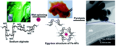
Nanostructured α-Fe2O3 with a carbon coating has advantages over commercially available graphitic anodes in lithium ion batteries, including high theoretical anodic capacity (1007 mA h g−1), low cost and environmental safety. However, parts of its merits were cancelled out by the current route used for its synthesis. For example, most of its synthesis pathways are tedious, costly, on small scale and environmentally unfriendly. By combining two naturally abundant materials (iron ions and sodium alginate) into conventional wet-spinning and pyrolysis processes, we show that α-Fe2O3 could be nanostructured and carbon-coated using a facile and yet scalable technique. The successful synthesis of nanostructured α-Fe2O3 within interconnected carbon shells strongly depends on the chelation of iron ions and alginate into “egg-box” networks and an optimized pyrolysis step. Due to an extraordinary combination of nanometric scale, improved electrical conductivity and spatial confinement of the carbon coating, the resultant materials exhibit a high lithium storage capacity (e.g. up to ∼1400 mA h g−1 at a current of 50 mA g−1 in the initial cycle) and great stability (e.g. ∼560 mA h g−1 after 600 cycles at 200 mA g−1) as well as a coulombic efficiency of 97.5%. Owing to the cost-efficient, environmentally friendly and scalable production, this synthesis may pave a highly promising way to the macroscopic preparation of α-Fe2O3/carbon hybrid materials as anodes in lithium ion batteries.


1. Introduction

Rechargeable lithium-ion batteries (LIBs) with super electrochemical properties have been in pursuit for decades to achieve an efficient, clean and sustainable energy storage for portable electronic devices, electric vehicles and smart utility grids.1–5 On account of the limited theoretical capacity (372 mA h g−1)6 and poor safety of commercially available graphite anodes,7 high-performance anode materials with high energy density and cycle stability have been particularly targeted to develop the next-generation of LIBs, e.g. transition-metal (i.e. Fe, Ni, Cu, and Co) oxides with theoretical capacities 2–3 times higher than graphitic anodes.8–12 As one of the most promising candidates, α-Fe2O3 (hexagonal corundum structure, a stable form of iron oxide) receives extraordinary interest due to its unique combination of high theoretical capacity (1007 mA h g−1), natural abundance, low cost and environmental friendliness.8,13 Considerable progress has been made to solve its bottle-necks for practical application as anodes, i.e. low electrical conductivity (leading to low rate capacity of LIBs) and undesirable volume expansion upon lithiation/delithiation (leading to rapid capacity loss and poor cycling stability of LIBs).13–16 However, many reported synthetic processes used to prepare high-performance anodes with α-Fe2O3 have undesirably canceled out its intrinsic advantages. For instance, their synthesis is normally tedious, costly, environmentally unfriendly (or even toxic), low yielding and on a small scale.13,15–17 A cost-efficient, scalable and environmentally friendly synthesis balanced with its high performance is still highly challenging for the industrial development of next-generation anodes with α-Fe2O3.

α-Fe2O3 has frequently been nanostructured and carbon-coated to enhance its charge/discharge rates and conductivity as well as relieving the mechanical stress derived from lithium insertion/extraction. Except costly carbon sources such as carbon nanotubes and graphene,14,15,18 diverse organic molecules (e.g. glucose,19 ethylene glycol,20 citric acid,21 furfuryl alcohol22 and dopamine23) have been used to coat pre-synthesized nanometric α-Fe2O3, followed by carbonizing hydrothermally, solvothermally or thermally. To economize the synthetic procedure, a one-pot strategy was adopted to synchronize the processes of nanosizing and carbonization, yet mostly for Fe3O4 and in low yield.13 Exceptionally, Chai proposed a one-step hydrothermal reaction of iron(III)nitrate in the presence of glucose to synthesize carbon-coated Fe2O3 nanoparticles.24 A more efficient synthesis was suggested by Cho concerning the high-temperature carbonization of electrospun nanofibers of polyacrylonitrile containing iron salts.16

Despite the considerable efforts mentioned above in industrializing carbon-coated and nanostructured α-Fe2O3 as an alternative to commercially available graphite anodes, an ideal approach still lacks in balancing its manufacturing cost and efficiency with the lithium storage performance in LIBs. Inspired by the natural biosynthesis of bone in living systems, wherein collagen fibers form scaffolds to spatially concentrate and mineralize calcium ions into apatite nanocrystals,25 we proposed in this study a facile and yet scalable approach to synthesize α-Fe2O3 anodes with comparable lithium storage performance. As shown in Scheme 1, iron ions were combined with naturally abundant alginate in a typical wet-spinning process to give cotton-like iron-alginate fibers (Fe-AFs) with a chelation network cross-linked by “egg-box” domains. After air-pyrolysis, the fibrous morphologies were surprisingly maintained with porous microstructures appropriate for further grinding into powder, in which α-Fe2O3 nanoparticles (with a diameter of 50–100 nm) embedded within interconnected thin carbon shells (with a thickness ∼10 nm) were obtained. This unique structure (i.e. α-Fe2O3 nanoparticles within interconnected thin carbon shells) is referred as “Fe2O3-in-C” through the entire text.


image file: c5ra21541b-s1.tif
Scheme 1 A schematic of the scalable pathway used to synthesize “Fe2O3-in-C”. (a) The combination of two naturally abundant materials (iron ions and marine sodium alginate) into a conventional wet-spinning process. (b) The optimized pyrolysis of Fe-AFs to give porous fibers appropriate for further grinding. (c) The facile grinding of the pyrolyzed Fe-AFs into the fine powder of “Fe2O3-in-C”.

The success and novelty of this approach lie in multiple points of view: (a) the recently developed method of metal-chelates as two-fold sources of carbon and iron combined together with a conventional fiber-spinning process. The former offers the possibility of “bottom-up” carbon-coating and nanostructuring of α-Fe2O3 in one step.26,27 The latter offers the opportunity of easily scaling up and industrializing this process. In addition to these advantages, the fiber structures obtained using this wet-spinning process also enable the homogenous chelation of alginate with iron ions and further homogenously pyrolyze into porous microstructures for the “Fe2O3-in-C” structure. (b) Two of the most naturally abundant materials (i.e. iron and alginate) were combined for the first time to fabricate anodes for LIBs, ensuring super sustainability and environmental friendliness. As a marine polysaccharide easily extracted from readily available brown algae,28 sodium alginate has received a lot of attention in the fields of food, environment, healthcare and fabric.29–32 In addition to its super properties in gelatinizing, film-forming, non-toxicity and biodegradability, its unique ability to immobilize metal ions within chelating “egg-box” networks enables fiber-spinning using a conventional wet-spinning procedure.33,34 (c) Pyrolysis conditions were optimized to achieve nanoscale α-Fe2O3 and further distribute it homogeneously within the interconnected thin carbon shells, in sharp contrast to iron oxides coated on porous carbon fibers described in our previous study.35 Last and yet most importantly, without losing its economic and environmental advantages, the resultant LIBs exhibit comparable capacity and cyclic stability with a high coulombic efficiency up to 97.5%.

2. Experimental section

2.1 Materials

Food-grade sodium alginate was extracted from brown algae and obtained from Shandong Jiejing Group Co., Ltd. (Shandong, China). FeCl3·6H2O (analytical grade) and hydrochloric acid (with the concentration of 37%) were purchased from Sinopharm Chemical Reagent Co., Ltd. (Beijing, China). Other chemicals were of analytical grade and used without further purification. All the aqueous solutions were prepared using Millipore water (resistivity at 25 °C: 18.2 MΩ cm−1).

2.2 Sample preparation

Fe-AFs were produced using a typical wet-spinning pathway as follows: sodium alginate was dissolved in Millipore water with vigorous stirring to achieve a homogeneous aqueous solution (5.0 wt%). The as-prepared solution was subsequently extruded from a spinneret (32 orifices, orifice diameter of 75 μm) into a coagulating solution of 5.0 wt% FeCl3 at 40 °C. The Fe-AFs were finalized by sequential treatments of drafting, water-washing and drying at 60 °C for 24 h.

For further carbonization and oxidation, the as-prepared Fe-AFs were heated at 5 °C min−1 in a quartz tube and maintained at 800 °C in air for 24 h. After several times washing with Millipore water, the resultant product was completely dried at 60 °C and then ground into a fine powder.

2.3 Characterization

Thermogravimetric analysis (TGA) was performed on a high-pressure thermogravimetric analyzer (DynTHERM series, Rubotherm GmbH, Gemany). 0.5 g sample was scanned at a ramp rate of 10 °C min−1 to 900 °C in air. Elemental analysis was performed on an Elementar Analysensysteme GmbH Vario EL Cube elemental analyzer. Field emission scanning electron microscopy (FESEM) was carried out with a JEOL 7401 instrument (JEOL, Japan) operated at 10 kV. The specimens were mounted on SEM stubs and coated with a 3 nm platinum layer. X-ray diffraction (XRD) measurements were taken on a D/max-RB X-ray diffractometer (Rigaku, Japan) with a Cu Kα radiation (λ = 1.5418 Å). The powder was leveled on sample holders and scanned with a 2θ angle within 20–80° and a step of 0.04°. High-resolution transmission electron microscopy (HRTEM) images were taken on a CM200/FEG HRTEM (Philips, Netherlands) equipped with electron energy-loss spectrometry (EELS) (Gatan, USA).

2.4 Electrochemical measurements

Electrochemical experiments were performed using standard R2032-type coin cells assembled in an argon-filled glove box (Mikrouna, China). A pure lithium foil (purchased from Aldrich) was used as the reference and counter electrode. The working electrode was prepared as follows: “Fe2O3-in-C” was mixed with poly(vinylidene fluoride) (PVDF) and acetylene black at a weight ratio of 8[thin space (1/6-em)]:[thin space (1/6-em)]1[thin space (1/6-em)]:[thin space (1/6-em)]1 using N-methyl-2-pyrrolidone (NMP) as the solvent to form a slurry. The slurry was coated uniformly onto a Cu foil substrate followed by vacuum-drying at 120 °C for 10 h and then pressed into films as the working electrode. The loading of active materials on each working electrode was 2.5 ± 0.3 mg. The electrolyte consisted of a LiPF6 solution (1 M) in ethylene carbonate-dimethyl carbonate (EC-DMC) (1[thin space (1/6-em)]:[thin space (1/6-em)]1 vol/vol). A porous polypropylene film (Celgard 2400) was used as the separator. Galvanostatic discharge–charge experiments were carried out on a Land Battery Measurement System over the potential range of 0.01–3.00 V. Cyclic voltammetry (CV) and electrochemical impedance spectroscopy (EIS) measurements were conducted on a CHI 660E electrochemical work station (Shanghai, China) at room temperature. CV was performed from 3.0 to 0.01 V at a scan rate of 0.5 mV s−1. EIS data (Nyquist plots) were recorded on an open circuit potential superimposed with an amplitude of 5.0 mV over a frequency range of 105 to 10−1 Hz, and simulation of the Nyquist plots was carried out with ZsimpWin software according to the proposed equivalent circuits. EIS was carried out on a newly-assembled cell both after hibernating for 6 h and fully discharging during the 600th discharge–charge cycle.

3. Results and discussion

3.1 Physical and chemical characterization

Though wet-spinning enables the scalable production of Fe-AFs, a key procedure to synthesize nanoscale α-Fe2O3 within the interconnected thin carbon shells is the subsequent pyrolysis process. The widely used carbonization process (i.e. thermally treating above 300 °C under nitrogen protection) produced Fe2O3/FeO nanoparticles coated on carbon fibers.35 Hence, both the atmosphere and temperature were tuned to optimize the carbonization conditions. A combination of TGA and XRD was used to evaluate the carbonization process and crystallographic forms of the iron oxides formed.

As shown in Fig. 1a, when pyrolyzing Fe-AFs in air at a heating rate of 10 °C min−1, the TGA curve reveals five distinct stages of weight loss. The initial weight loss below 200 °C was a result of water dehydration, as described for sodium alginate.35,36 The second stage between 200 and 300 °C gives a loss ratio of ∼50%, ascribed to the decomposition of Fe-AFs by breaking the alginate chains into intermediate compounds and gas molecules of H2, CO, CO2, and H2O.37–40 The third stage between 300 and 500 °C corresponds to the degradation and carbonization of organic intermediate compounds, wherein volatile compounds were released from the system together with pyrolytic decomposition and thermal polymerization.38,39 High temperature carbonization of organics may take part in the pyrolysis process35 when gradually approaching 500 °C. Moreover, XRD measurements (see Fig. 1b & S1) proved the formation of a mixture of ferrum oxides (e.g. Fe3O4 and Fe2O3). During the fourth steady stage between 500 and 800 °C, low-valence of iron oxides were oxidized to high-valence, whereas carbon was slightly burnt upon oxidization. For instance, no trace of Fe3O4 other than α-Fe2O3 was observed at 800 °C (Fig. 1b), whose diffraction peaks could be perfectly indexed to α-Fe2O3 (JCPDS no. 33-0664). The intensified diffraction peaks of α-Fe2O3 upon increasing the temperature indicate an increasing crystallinity, in sharp contrast to the carbothermic reaction occurring under nitrogen protection, which conventionally converts high-valence ferrum oxides to low-valence ferrum oxides. This is probably because oxygen has a higher oxidability than ferric iron under the oxygen-rich pyrolysis atmosphere. More carbon burning appears above 800 °C and was accompanied with a rapid weight loss (Fig. 1a). As to the XRD patterns of Fe-AFs before heating (Fig. S2), there are no peaks of any iron oxide observed, which indicates that α-Fe2O3 was generated during the pyrolysis step. Notably, a XRD hump located at 25–27° in all the curves shown in Fig. 1b was characteristic of the (002) reflection of disordered carbon materials.41


image file: c5ra21541b-f1.tif
Fig. 1 (a) The TGA curve showing the five stages of Fe-AFs pyrolysis in air (solid line) and the TGA curve for “Fe2O3-in-C” calcined in air (short dot line). (b) The XRD patterns of Fe-AFs pyrolyzed at 600–800 °C.

According to the TGA results described in Fig. 1 & S1, the optimal synthesis conditions of nanoscale and carbon-coated α-Fe2O3 seem to be at 800 °C in air, wherein a controllable amount of carbon (e.g. 6.17 wt% calculated by the weight loss of the as-prepared “Fe2O3-in-C” that is in good agreement with the result from elemental analysis of 6.42 wt%) could be maintained and Fe could convert completely to highly crystalline α-Fe2O3. Nevertheless, lower temperatures give not only the unpreferred existence of Fe3O4 but also excess carbon. In addition, higher temperatures may consume the carbon coating completely.

The morphologies of pyrolytic Fe-AFs at 800 °C were investigated by SEM. Unlike collapsing carbonaceous materials from pyrolytic biopolymer fibers,42,43 their fibrous feature was retained (Fig. 2a) with an average fiber diameter of 5–7 μm, which was only 1/2–2/3 of their precursor Fe-AFs (average diameter of ca. 15 μm in Fig. S3). In spite of this radial shrinkage, closer examination in Fig. 2b surprisingly demonstrates porous microstructures, wherein ellipsoid nanoparticles scaled with 50–100 nm (Fig. 2c) scaffolded the fibrous matrix. The TEM images shown in Fig. 2d and e further reveal ambiguously the existence of interconnected thin carbon-shells (with a thickness of ∼10 nm), within which the nanostructured α-Fe2O3 was embedded. These porous fibers enable facile grinding into a fine powder of nanoscale α-Fe2O3 within the interconnected thin carbon shells for use as electrodes in LIBs.


image file: c5ra21541b-f2.tif
Fig. 2 (a) The SEM morphology of Fe-AFs after pyrolysis at 800 °C. (b) The zoom-in image of (a). The (c) SEM, (d) TEM and (e) HRTEM images of “Fe2O3-in-C” after grinding the pyrolytic Fe-AFs. (f) The EELS spectrum of Fe2O3.

The successful synthesis of α-Fe2O3 was further confirmed by HRETM and EELS. As shown in Fig. 2e, the presence of d-spacing of 2.56 and 2.63 Å corresponds perfectly to the (110) and (104) cryptographic planes of α-Fe2O3.44 Fig. 2f exhibits the typical energy loss peaks of Fe L2,3-edge at ∼710 eV and O–K edge peaks at ∼539 eV.45 Through quantitative calculation, the atomic ratio between Fe and O was revealed as 2[thin space (1/6-em)]:[thin space (1/6-em)]3, being identical with that of α-Fe2O3. The elemental distribution of Fe, O as well as C in the “Fe2O3-in-C” materials was also confirmed by SEM-element mapping, as shown in Fig. S4.

3.2 Electrochemical characterization

Due to the extraordinary combination of nanoscale, improved electrical conductivity and spatial confinement of the carbon coating, the “Fe2O3-in-C” produced through this unique pathway has an attractive application as anodes for energy storage. Their electrochemical properties were evaluated in detail, as shown in Fig. 3. The first three cycles of CV were performed at a scan rate of 0.1 mV s−1 within 0.01–3.0 V (Fig. 3a). In the first cycle, there appeared four cathodic peaks (indicated as CIV, CIII, CII and CI) and two anodic peaks (indicated as AI and AII). The cathodic peak (CIV) at 0.68 V was ascribed to the reduction of Fe(III) to Fe(0), formation of Li2O and irreversible reactions of the electrolyte in forming solid electrolyte interphases (SEI).16 Three shoulder peaks at 1.26 (CI), 1.04 (CII) and 0.91 V (CIII) signify a multi-step intercalation of Li+ into the anodes to form intermediate LixFe2O3 (0 ≤ x < 2).46 The two anodic peaks (AI and AII) at 1.65 and 1.84 V were a result of the oxidation of Fe(0) to Fe(II) and Fe(II) to Fe(III), respectively.24 During the second CV cycle, the cathodic peaks shift to higher voltages with much lower intensity, confirming the successful formation of SEI in the first cathodic sweep. The intensity of the two anodic peaks was also depressed at the nearly same positions. Remarkably, the CV curves were highly repeatable in the subsequent sweeps, demonstrating the great stability and reversibility of this material as an LIB anode.
image file: c5ra21541b-f3.tif
Fig. 3 The electrochemical performance of the “Fe2O3-in-C” anodes. (a) The first three CVs over a potential range of 3.0–0.01 V at a scan rate of 0.1 mV s−1. (b) The first three discharge–charge curves over the potential range of 3.0–0.01 V at a current density of 50 mA g−1. The inset gives the first discharge curve with the potential within 2.0–1.0 V. (c) The rate and cycling properties for the first 30 discharge–charge cycles at different current densities. (d) The rate and cycling properties up to 600 discharge–charge cycles.

To understand how the capacity was delivered, discharge–charge tests were performed at a current density of 50 mA g−1 within 0.01–3.0 V (Fig. 3b). In the first cycle, a high discharge capacity of 1415 mA h g−1 was achieved for Li intercalation, which calculates a coulombic efficiency of 67.2% with a charge capacity of 951 mA h g−1. In the second cycle, both the discharge and charge capacities decreased (980 and 920 mA h g−1, respectively), whereas increasing its coulombic efficiency as high as 93.9%. Among the four voltage plateaus observed in the first discharge curve, the main plateau (indicated as IV) around 0.91 V demonstrates the reactions involving the reduction to Fe(0) and the formation of SEI layers. The formation of the SEI and multiple-step lithiation could also be identified in Fig. 4a and b. The plateau regions (indicated as I, II and III) at 1.65, 1.40 and 1.17–0.90 V demonstrate the multi-step intercalation of Li+ to LixFe2O3 (0 ≤ x < 2). Based on the results described above, the lithiation of α-Fe2O3 may proceed via the following steps:17,47

 
Fe2O3 + xLi+ + xe → LixFe2O3 (0 ≤ x < 2) (1)
 
LixFe2O3 + (6 − x)Li+ + (6 − x)e → 3Li2O + 2Fe (0 ≤ x < 2) (2)


image file: c5ra21541b-f4.tif
Fig. 4 The EIS (a) before and (b) after long-term discharge–charge cycling. The fitted spectra are given as a continuous line. The equivalent circuits are exhibited in the insets. The (c) SEM morphologies and (d) XRD pattern of the electrode materials after long-term discharge–charge cycling. The Cu peaks are from the copper foil, which serves as the current collector in the LIB.65

Thus, the net reaction becomes as follows:

 
Fe2O3 + 6Li+ + 6e → 3Li2O + 2Fe (3)

This anodic material was subsequently examined with its rate and cycling performance (Fig. 3c & d). By step-increasing the current density from 50 to 1000 mA g−1 (Fig. 3c), its average discharge capacity decreased progressively from 960 to 278 mA h g−1. Upon resetting the current density to 200 mA g−1, a rebounding discharge capacity of 443 mA h g−1 indicates the super tolerance of the anode against high current density. The superior charge–discharge cycling stability is denoted in Fig. 3d. In spite of a slight decrease in the initial 50 cycles, the discharge capacity at a current density of 200 mA g−1 increased gradually up to 560 mA h g−1 after 600 cycles. For iron oxide electrodes, this increasing trend likely originates in kinetically activated electrolyte degradation,15,47 which produces polymeric gel-type regions (SEI membranes) for reversible lithium storage. It is widely accepted that the decomposition of electrolyte mainly occurs during the first discharge process.48–51 The decomposition products together with Li+ will form insoluble compounds (e.g. (CH2OCOOLi)2, CH3OCOOLi, Li2CO3, and LiOH) that deposit on the surface of the electrode materials to form the so-called SEI. When the oxides of 3d-metals (like Fe, Cu, Ni) serve as anodes, the degradation of the electrolyte may be kinetically activated by these metals, leading to the reversible growth of the SEI film and hereby resulting in an increasing capacity in the long discharge–charge.52 With the assistance of the additional activating effect of the interconnected carbon shells, the process of electrochemical activation prolonged even longer than that reported in the literature.15,47 The carbon shells could also protect the electrode material from pulverization and alleviate its volume swing, consequently offering long-term discharge stability. The superior charge–discharge reversibility was confirmed by its coulombic efficiency, which remains as high as 97.5% during the 600th cycle. As summarized in Table 1, the present performance of the “Fe2O3-in-C” electrode was comparable to those reported in the literature especially during long-term cycling. Notably, the specific energy capacity per volume is of great importance in practical applications. Based on the tap density of “Fe2O3-in-C” powder (1.24 g cm−3, three times averaged), “Fe2O3-in-C” exhibits reassuring performances as shown in Fig. S5 (e.g. ∼670 mA h cm−3 after 600 cycles at a current density of 200 mA g−1). Moreover, the readily available constructing materials (alginate and iron) and the scalability of the conventional wet-spinning and pyrolysis processes render a promising future for the macroscopic preparation and practical application of “Fe2O3-in-C” materials.

Table 1 Summary of the representative α-Fe2O3-based anode materials used for lithium-ion batteries
Electrode materials Electrochemical properties Ref.
Period (cycles) Capacity (mA h g−1) Current density (mA g−1)
α-Fe2O3 microparticles 100 662 200 53
α-Fe2O3 nanoneedles 100 456 ∼100 54
α-Fe2O3 nanosheets 50 518 ∼100 55
Hydrothermal carbon coated nano-Fe2O3 20 ∼400 100 24
α-Fe2O3 nanohorns on carbon nanotube 100 ∼500 500 56
Fe2O3/reduced graphene oxide hydrogel 70 ∼600 200 57
Fe2O3-20 wt% graphite composite 55 491 100 8
Fe2O3/C nano-composites 80 470 125 58
Ag-incorporated Fe2O3/carbon nanofibers 65 560 600 59
“Fe2O3-in-C” 600 560 200 This study


Based on the cells of “Fe2O3-in-C” versus Li on an open circuit potential, EIS measurements were carried out and plotted as the Nyquist curves. The impedance data were analyzed according to the equivalent circuits shown in the inset of Fig. 4a and b. Before long-term discharge–charge cycling, the Nyquist curve consists of a semicircle at high-medium frequencies and a short slope of ∼45° at low frequencies, which result from the interfacial charge transfer on the electrode and frequency-dependent ion diffusion in the electrolyte to the electrode, respectively.41,60 Correspondingly, the equivalent circuit consists of an electrolyte resistance (Rs) (identified as the intercept of the EIS curve at the Z′ axis), a charge transfer resistance (Rct) (identified as the diameter of the semicircle), a constant phase element (CPEct) for amending the depressed semicircle instead of pure capacitance and a diffusional component of Warburg impedance (Ws).61 After long-term discharge–charge cycling, an extra semicircle appeared in the counterpart Nyquist curve, which was ascribed to the polarization mainly from the SEI film. Accordingly, a polarization circuit, including Rp and CPEp, was added to the equivalent circuit for evaluation of the side reactions in the SEI.62

According to the calculated results shown in Table 2 and S1, the value of Rct (145 ohm) before long-term cycling was much lower than those of other iron oxide anodes reported in the literature,15 showing that the presence of interconnected carbon shells renders a high electron conductivity and fast charge transfer at the interfaces. After long-term cycling, an improved conductivity was clarified by a dramatic decrease in Rct from 145 to 18.4 ohm. This observation could be rationalized by metallic iron generated in the discharge process, as described in Fig. 4d. Moreover, the low value of Rp (2.96 ohm) confirms that the Li+ efficiently intercalated into and out of the SEI. Apparently, the improved conductivity could help improve the performance of LIBs by avoiding unwanted heat during the charge/discharge process.41

Table 2 Resistances of the equivalent circuit obtained before and after long-term discharge–charge cycling
Elements Rs (ohm) Rct (ohm) Rp (ohm)
Before cycling 6.16 145
After cycling 5.09 18.4 2.93


The effect of long-term discharge–charge on the physico-chemical structures of the anodic materials was evaluated by both SEM and XRD. As shown in Fig. 4c and S6, cycling does not seem to alter the morphology of the nanostructured α-Fe2O3, demonstrating that the carbon shells successfully curbed the volumetric changes and pulverization occurring during Li+ intercalation/de-intercalation. The surfaces of the “Fe2O3-in-C” materials turned rough after cycling (Fig. 4c & S6). Combined with the ESI analysis, it can be strongly proved that the SEI film was formed on the surface of the cycled materials. A strong and stable SEI film is known to be capable of effectively protecting an anodic material and preventing pulverization, thereby endowing the LIBs great stability during long-term discharge–charge and a long service life.23,62 The transformation of α-Fe2O3 into metallic iron during long-term cycling is exhibited in Fig. 4d.63,64 Moreover, there are no peak characteristics of crystalline Li2O observed, which was in agreement with its amorphous form.62

4. Conclusions

Due to the formation of chelating “egg-box” networks, two of the most naturally abundant materials, i.e. iron ions and marine sodium alginate, were combined into a conventional wet-spinning process. When the pyrolysis conditions were precisely optimized at 800 °C in air, the resultant iron-alginate fibers could further transform into α-Fe2O3 nanoparticles (with a diameter of 50–100 nm) within interconnected thin carbon shells (with a thickness ∼10 nm). This unique combination of nanostructured α-Fe2O3 and carbonized alginate offers an economic and environmentally friendly approach towards the scalable synthesis of α-Fe2O3/carbon hybrid anodes for high-performance lithium ion batteries. The high reversible capacity and super long-term stability of the anode were investigated using CV, EIS and discharge–charge tests. The thin carbon shells offer not only conductive networks for rapid electron transport, but also as a barrier for the aggregation and pulverization of α-Fe2O3. In brief, the availability and sustainability of the constructing materials and the scalability of conventional wet-spinning and pyrolysis processes render a promising route for future industrial production of high-performance anodes.

Acknowledgements

The National Key Technology R&D Program of the Ministry of Science and Technology (No. 2015BAD14B06), the National Natural Science Foundation of China (No. 21474125), the Shandong Collaborative Innovation Center for marine biomass fiber materials and textiles and the Chinese “1000 youth Talent Program” are kindly acknowledged for financial support.

References

  1. J. Liu, P. Kopold, P. A. van Aken, J. Maier and Y. Yu, Angew. Chem., Int. Ed. Engl., 2015, 54, 9632–9636 CrossRef CAS PubMed.
  2. J. Zhang, L. Yue, Q. Kong, Z. Liu, X. Zhou, C. Zhang, Q. Xu, B. Zhang, G. Ding, B. Qin, Y. Duan, Q. Wang, J. Yao, G. Cui and L. Chen, Sci. Rep., 2014, 4, 3935,  DOI:10.1038/srep03935.
  3. Q. Xu, Q. Kong, Z. Liu, X. Wang, R. Liu, J. Zhang, L. Yue, Y. Duan and G. Cui, ACS Sustainable Chem. Eng., 2014, 2, 194–199 CrossRef CAS.
  4. M. Armand and J. M. Tarascon, Nature, 2008, 451, 652–657 CrossRef CAS PubMed.
  5. Y. Liu, J. Gu, J. Zhang, F. Yu, J. Wang, N. Nie and W. Li, RSC Adv., 2015, 5, 9745–9751 RSC.
  6. X. Wang, L. Sun, X. Hu, R. A. Susantyoko and Q. Zhang, J. Power Sources, 2015, 280, 393–396 CrossRef CAS.
  7. J. S. Chen, L. A. Archer and X. Wen Lou, J. Mater. Chem., 2011, 21, 9912–9924 RSC.
  8. Y. Wang, L. Yang, R. Hu, L. Ouyang and M. Zhu, Electrochim. Acta, 2014, 125, 421–426 CrossRef CAS.
  9. C. Zhang, S. Pang, Q. Kong, Z. Liu, H. Hu, W. Jiang, P. Han, D. Wang and G. Cui, RSC Adv., 2013, 3, 1336–1340 RSC.
  10. J. Liu, W. Liu, K. Chen, S. Ji, Y. Zhou, Y. Wan, D. Xue, P. Hodgson and Y. Li, Chemistry, 2013, 19, 9811–9816 CrossRef CAS PubMed.
  11. J. Liu, Y. Zhou, F. Liu, C. Liu, J. Wang, Y. Pan and D. Xue, RSC Adv., 2012, 2, 2262–2265 RSC.
  12. J. Liu, Y. Zhou, C. Liu, J. Wang, Y. Pan and D. Xue, CrystEngComm, 2012, 14, 2669–2674 RSC.
  13. L. Zhang, H. B. Wu and X. W. D. Lou, Adv. Energy Mater., 2014, 4, 1300958,  DOI:10.1002/aenm.201300958.
  14. J. Hu, J. Zheng, L. Tian, Y. Duan, L. Lin, S. Cui, H. Peng, T. Liu, H. Guo, X. Wang and F. Pan, Chem. Commun., 2015, 51, 7855–7858 RSC.
  15. Y. Wang, L. Yang, R. Hu, W. Sun, J. Liu, L. Ouyang, B. Yuan, H. Wang and M. Zhu, J. Power Sources, 2015, 288, 314–319 CrossRef CAS.
  16. J. S. Cho, Y. J. Hong and Y. C. Kang, ACS Nano, 2015, 9, 4026–4035 CrossRef CAS PubMed.
  17. T. R. Penki, S. Shivakumara, M. Minakshi and N. Munichandraiah, Electrochim. Acta, 2015, 167, 330–339 CrossRef CAS.
  18. G. Gao, Q. Zhang, X.-B. Cheng, P. Qiu, R. Sun, T. Yin and D. Cui, ACS Appl. Mater. Interfaces, 2015, 7, 340–350 CAS.
  19. Q. Q. Xiong, Y. Lu, X. L. Wang, C. D. Gu, Y. Q. Qiao and J. P. Tu, J. Alloys Compd., 2012, 536, 219–225 CrossRef CAS.
  20. Q. Zhang, Z. Shi, Y. Deng, J. Zheng, G. Liu and G. Chen, J. Power Sources, 2012, 197, 305–309 CrossRef CAS.
  21. H. Liu, G. Wang, J. Wang and D. Wexler, Electrochem. Commun., 2008, 10, 1879–1882 CrossRef CAS.
  22. Y. Piao, H. S. Kim, Y.-E. Sung and T. Hyeon, Chem. Commun., 2010, 46, 118–120 RSC.
  23. C. Lei, F. Han, D. Li, W. C. Li, Q. Sun, X. Q. Zhang and A. H. Lu, Nanoscale, 2013, 5, 1168–1175 RSC.
  24. X. Chai, C. Shi, E. Liu, J. Li, N. Zhao and C. He, Appl. Surf. Sci., 2015, 347, 178–185 CrossRef CAS.
  25. F. Nudelman, K. Pieterse, A. George, P. H. H. Bomans, H. Friedrich, L. J. Brylka, P. A. J. Hilbers, G. de With and N. A. J. M. Sommerdijk, Nat. Mater., 2010, 9, 1004–1009 CrossRef CAS PubMed.
  26. J. S. Chen, Y. Zhang and X. W. Lou, ACS Appl. Mater. Interfaces, 2011, 3, 3276–3279 CAS.
  27. B. Jang, M. Park, O. B. Chae, S. Park, Y. Kim, S. M. Oh, Y. Piao and T. Hyeon, J. Am. Chem. Soc., 2012, 134, 15010–15015 CrossRef CAS PubMed.
  28. S. N. Pawar and K. J. Edgar, Biomaterials, 2012, 33, 3279–3305 CrossRef CAS PubMed.
  29. L. Wang, R. M. Shelton, P. R. Cooper, M. Lawson, J. T. Triffitt and J. E. Barralet, Biomaterials, 2003, 24, 3475–3481 CrossRef CAS PubMed.
  30. C. J. Knill, J. F. Kennedy, J. Mistry, M. Miraftab, G. Smart, M. R. Groocock and H. J. Williams, Carbohydr. Polym., 2004, 55, 65–76 CrossRef CAS.
  31. R. Y. M. Huang, R. Pal and G. Y. Moon, J. Membr. Sci., 1999, 160, 101–113 CrossRef CAS.
  32. I. A. Brownlee, A. Allen, J. P. Pearson, P. W. Dettmar, M. E. Havler, M. R. Atherton and E. Onsøyen, Crit. Rev. Food Sci. Nutr., 2005, 45, 497–510 CrossRef CAS PubMed.
  33. D. Li, D. Yang, X. Zhu, D. Jing, Y. Xia, Q. Ji, R. Cai, H. Li and Y. Che, J. Mater. Chem. A, 2014, 2, 18761–18766 CAS.
  34. X.-L. Wu, L.-L. Chen, S. Xin, Y.-X. Yin, Y.-G. Guo, Q.-S. Kong and Y.-Z. Xia, ChemSusChem, 2010, 3, 703–707 CrossRef CAS PubMed.
  35. B. Wang, Q. Kong, F. Quan, Q. Ji and Y. Xia, J. Appl. Polym. Sci., 2013, 128, 2216–2223 CAS.
  36. E. Raymundo-Piñero, F. Leroux and F. Béguin, Adv. Mate., 2006, 18, 1877–1882 CrossRef.
  37. G. Tian, Q. Ji, D. Xu, L. Tan, F. Quan and Y. Xia, Fibers Polym., 2013, 14, 767–771 CrossRef CAS.
  38. Y. Liu, J.-C. Zhao, C.-J. Zhang, Y. Guo, L. Cui, P. Zhu and D.-Y. Wang, RSC Adv., 2015, 5, 64125–64137 RSC.
  39. Y. Liu, Z. Li, J. Wang, P. Zhu, J. Zhao, C. Zhang, Y. Guo and X. Jin, Polym. Degrad. Stab., 2015, 118, 59–68 CrossRef CAS.
  40. S. Bekin, S. Sarmad, K. Gurkan, G. Yenici, G. Keceli and G. Gurdag, Polym. Eng. Sci., 2014, 54, 1372–1382 CAS.
  41. M. Li, C. Liu, H. Cao, H. Zhao, Y. Zhang and Z. Fan, J. Mater. Chem. A, 2014, 2, 14844–14851 CAS.
  42. B. Zhang, M. Xiao, S. Wang, D. Han, S. Song, G. Chen and Y. Meng, ACS Appl. Mater. Interfaces, 2014, 6, 13174–13182 CAS.
  43. Z.-Q. Zhao, P.-W. Xiao, L. Zhao, Y. Liu and B.-H. Han, RSC Adv., 2015, 5, 73980–73988 RSC.
  44. S. L. Bai, J. H. Zhao, G. X. Du, J. F. Zheng and Z. P. Zhu, Nanotechnology, 2008, 19, 205605,  DOI:10.1088/1957-4484/19/20/205605.
  45. U. Golla-Schindler, G. Benner and A. Putnis, Ultramicroscopy, 2003, 96, 573–582 CrossRef CAS PubMed.
  46. B. Tian, J. Światowska, V. Maurice, S. Zanna, A. Seyeux, L. H. Klein and P. Marcus, Langmuir, 2014, 30, 3538–3547 CrossRef CAS PubMed.
  47. H. Yang, X. Yu, H. Meng, P. Dou, D. Ma and X. Xu, J. Mater. Sci., 2015, 50, 5504–5513 CrossRef CAS.
  48. E. Peled, J. Electrochem. Soc., 1979, 126, 2047–2051 CrossRef CAS.
  49. S. Laruelle, S. Grugeon, P. Poizot, M. Dollé, L. Dupont and J.-M. Tarascon, J. Electrochem. Soc., 2002, 149, A627–A634 CrossRef CAS.
  50. J. S. Do and C. H. Weng, J. Power Sources, 2005, 146, 482–486 CrossRef CAS.
  51. G. Zhou, D.-W. Wang, F. Li, L. Zhang, N. Li, Z.-S. Wu, L. Wen, G. Q. Lu and H.-M. Cheng, Chem. Mater., 2010, 22, 5306–5313 CrossRef CAS.
  52. S. Grugeon, S. Laruelle, L. Dupont and J. M. Tarascon, Solid State Sci., 2003, 5, 895–904 CrossRef CAS.
  53. J. S. Chen, T. Zhu, X. H. Yang, H. G. Yang and X. W. Lou, J. Am. Chem. Soc., 2010, 132, 13162–13164 CrossRef CAS PubMed.
  54. H. Liu, D. Wexler and G. Wang, J. Alloys Compd., 2009, 487, L24–L27 CrossRef CAS.
  55. D. Lei, M. Zhang, B. Qu, L. Chen, Y. Wang, E. Zhang, Z. Xu, Q. Li and T. Wang, Nanoscale, 2012, 4, 3422–3426 RSC.
  56. Z. Wang, D. Luan, S. Madhavi, Y. Hu and X. W. Lou, Energy Environ. Sci., 2012, 5, 5252–5256 CAS.
  57. W. Zhou, C. Ding, X. Jia, Y. Tian, Q. Guan and G. Wen, Mater. Res. Bull., 2015, 62, 19–23 CrossRef CAS.
  58. P. Li, J. Deng, Y. Li, W. Liang, K. Wang, L. Kang, S. Zeng, S. Yin, Z. Zhao, X. Liu, Y. Yang and F. Gao, J. Alloys Compd., 2014, 590, 318–323 CrossRef CAS.
  59. M. Zou, J. Li, W. Wen, L. Chen, L. Guan, H. Lai and Z. Huang, J. Power Sources, 2014, 270, 468–474 CrossRef CAS.
  60. M. Li, C. Liu, Y. Xie, H. Cao, H. Zhao and Y. Zhang, Carbon, 2014, 66, 302–311 CrossRef CAS.
  61. M. V. Reddy, T. Yu, C. H. Sow, Z. X. Shen, C. T. Lim, G. V. Subba Rao and B. V. R. Chowdari, Adv. Funct. Mater., 2007, 17, 2792–2799 CrossRef CAS.
  62. J. Lu, C. Nan, L. Li, Q. Peng and Y. Li, Nano Res., 2013, 6, 55–64 CrossRef CAS.
  63. Y. Li, W. Cheng, G. Sheng, J. Li, H. Dong, Y. Chen and L. Zhu, Appl. Catal., B, 2015, 174–175, 329–335 CrossRef CAS.
  64. M. Nabiałek, J. Alloys Compd., 2015, 642, 98–103 CrossRef.
  65. D. Duan, H. Liu, X. You, H. Wei and S. Liu, J. Power Sources, 2015, 293, 292–300 CrossRef CAS.

Footnotes

Electronic supplementary information (ESI) available. See DOI: 10.1039/c5ra21541b
J. Qiu & M. Li contributed equally to this work.

This journal is © The Royal Society of Chemistry 2016
Click here to see how this site uses Cookies. View our privacy policy here.