Evaluation of electrical, dielectric and magnetic characteristics of Al–La doped nickel spinel ferrites

Hafiz Sartaj Aziza, Saadia Rasheeda, Rafaqat Ali Khan*a, Abdur Rahimb, Jan Nisarc, Syed Mujtaba Shahd, Farasat Iqbalb and Abdur Rahman Khan*a
aApplied and Analytical Chemistry Laboratory, Department of Chemistry, COMSATS Institute. of Information Technology, Abbottabad 22060, Khyber Pakhtunkhwa, Pakistan. E-mail: khanar@ciit.net.pk; rafaqat2khan@yahoo.com; Fax: +92-992-383441; Tel: +92-992-383591(314), +92-340-9324600
bInterdisciplinary Research Center in Biomedical Materials, COMSATS Institute of Information Technology, Lahore, Pakistan
cNational Center of Excellence in Physical Chemistry, University of Peshawar, Khyber Pakhtunkhwa, Pakistan
dDepartment of Chemistry, Quaid-i-Azam University, Islamabad 45320, Pakistan

Received 10th October 2015 , Accepted 6th January 2016

First published on 11th January 2016


Abstract

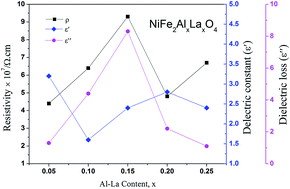
The paper reports the effects of lanthanum and aluminum ions, on the structural, electrical and magnetic properties of NiFe2O4 spinel ferrite nanoparticles. The precursors have been synthesized via a hydrothermal route in the presence of ascorbic acid (AA) using urea as a reducing agent and fuel for maintaining the uniform morphology and equal particle size distribution. In order to find out the optimum temperature (1023 K) for the formation of the spinel phase of the doped nickel ferrite, thermogravimetric analysis (TGA) for the un-annealed samples was performed. The X-ray diffraction patterns show that NiFe2−2xAlxLaxO4 have been well crystallized to spinel ferrite crystal structure with the Fd3m space group. The average crystallite size obtained is in the range of 9–19 nm, a size useful for attaining a suitable signal-to-noise ratio in high-density recording media and in electrical devices. In order to render the synthesized samples for diminishing eddy current losses, we were able to enhance the room temperature resistivity through proper selection of dopant used. The dielectric constant and dielectric loss decreased with applied frequency for all the samples showing normal behavior of ferrites. The calculated magnetic parameters such as saturation magnetization (Ms), remanence (Mr) and coercivity (Hc), showed increased values for some Al–La doped samples.


1. Introduction

Nanomaterials have continued as a focus area during the past few decades owing to their superior properties as compared to their bulk counterparts.1,2 Many factors such as grain and grain boundary structure, particle size distribution and inter-particle interactions in the system regulate the behavior of nanoparticles.3 The drastic variations in the electrical and magnetic properties of ferrites are due to their increased surface to volume ratio that leads to increased atomic reactivity on the surface of particles as compared to those present within the particle.4 Recently, the ferrites have been extensively studied because of their wide range of technological applications in various fields including hyperthermia,5 cell biology and molecular imaging.6 Having tetrahedral A- and octahedral B-sites in their crystal structure,7 the physical characteristics of spinel ferrites are deeply affected by the cation distribution among these sites.8 The high electrical resistivity for attaining low eddy current losses and enhanced magnetic properties for applications in high density recording media, made nickel ferrite a material of choice particularly in the radio frequency region.9

Introducing a small amount of rare earth ions in the crystal structure of spinel ferrites can have considerable effects on the structural, electrical and magnetic properties.10 Single-phase rare earth doped nickel ferrites NiFe2−xRxO4 (Tb3+) with cubic spinel structure were synthesized via conventional solid-state reaction and soft chemistry techniques with dopant concentrations below x = 0.1.11 Substitution caused an increase in lattice constant because of the greater ionic radii of rare earth ions. It was also reported that doping rare earth ions (Y3+, Gd3+, Eu3+) created local distortion and disorder that caused the softening of the crystal structure network.12 Rare earth ions (Dy3+, Gd3+, Sm3+, Ce3+) in such structures favour to reside in the octahedral sites due to the smallness of the tetrahedral sites and these ions are hard to diffuse into the lattice to process the growth of the ferrite particles.13 The doping of rare earth ions (Sm3+, Gd3+, Dy3+) also enhanced the electrical resistivity of nickel ferrite for use in high frequency applications.14 Moreover, the replacement of Fe ions with Ho3+ ions in the spinel lattice resulted in the lowering of the spontaneous magnetization and Curie temperature values.15 Therefore, various reports that combine different experimental approaches are very helpful in the elucidation of the actual amount of rare earth ions in the crystal lattice and their effects on different physical properties for potential applications in different fields.

This work presents a detailed study on the electrical, dielectric and magnetic properties of the nonmagnetic Al3+ and La3+ ions doped NiFe2−2xAlxLaxO4 ferrite synthesized via hydrothermal method. There are different method used for ferrite synthesis e.g. sol–gel method, co-precipitation method, microemulsion method and hydrothermal method etc. In sol–gel method a very high temperature is required to attain crystallinity otherwise prepared material will always be in the amorphous form.16 Moreover, co-precipitation method has a drawback of controlling the particle size and distribution. Most of the times, fast (uncontrolled) precipitation takes place that could results in large particles17 Similarly, microemulsion method has complications like low yield of the required products.18 However, the hydrothermal method is a simple method of synthesis and is the most promising method for the fabrication of nanostructures and microstructures with high crystallinity, high purity, and narrow particle size distribution at low temperature and under high pressure. It has been shown that the concentration of reagents, the reaction temperature, the reaction time and the surfactants are important factors in influencing the structural growth of the products.19 Aluminium ions have been proven to have substantial influence on the properties of nickel ferrites, especially these ions increase resistivity and thus reduce eddy current losses.20 Furthermore, the nonmagnetic Al3+ substitution in Ni–Zn–ferrite causes grain refinement and modifies the magnetic properties up to a pronounced level as well.21,22 The purpose of La doping is to improve the electrical resistivity, and decrease both the dielectric constant and dielectric loss. The study is invaluable in providing some insights into the potential of using nickel spinel ferrite nanomaterials for the next generation of magnetic and microwave devices (filters, phase-shifters, circulators, etc.) and transformer cores.

2. Experimental procedure

Various chemical used for the synthesis were Ni(NO3)3·6H2O, Fe(NO3)3·9H2O, La(NO3)3·6H2O, Al(NO3)3·6H2O, ascorbic acid (AA) C6H8O6 and urea CO(NH2)2 with purity of all chemicals in a range from 98–99%. NiFe2−2xAlxLaxO4 (x = 0.05, 0.1, 0.15, 0.20, 0.25) spinel ferrite powders were synthesized via hydrothermal method. In the initial step, the molar amounts of metal salts in a required ratio along with 1 g of AA (C6H8O6) and 1.2 g of CO(NH2)2 were dissolved into a 130 mL of distilled water. The solution mixture was stirred for 15 min to obtain a homogeneous solution and then transferred to a Teflon autoclave where it was heat treated at 180 °C for 6 h. The precipitates thus obtained were washed several times with distilled water and then dried at 90 °C for 24 h. Finally, the powder were further annealed at 750 °C for 4 h in an electrical furnace to obtain the NiFe2−2xAlxLaxO4 nanoparticles. The as prepared samples were thermally characterized using a Simultaneous Thermogravimetric/Differential Thermal Analyzer (TG/DTA, model: SDT Q600) to get an idea about the optimum annealing temperature. Phase purity was determined by powder X-ray diffraction (XRD) technique using diffractometer (Phillips X'Pert PRO 3040/60) that employs CuKα radiations. The scanning images were acquired in secondary electron mode using tungsten filament based scanning electron microscope (VEGA3 LM, TESCAN, Czech Republic). Room temperature electrical resistivity measurements were carried out using two-point probe technique. RF Impedance material analyzer (Agilent E4991A) was used to measure dielectric parameters of silver-coated pellets with a diameter of 13 mm and a thickness of 2 mm. Magnetic parameters such as saturation magnetization, remanent magnetization and coercivity were determined using vibrating sample magnetometer (VSM) at room temperature.

3. Results and discussion

3.1 Thermal analysis

Thermogravimetric analysis curve for an un-annealed compound with a proposed composition of NiFe1.9Al0.05La0.05O4 is shown in Fig. 1. As indicated, the figure exhibits four weight losses in the temperature range of 20–600 °C. The first weight loss in the temperature range 20–150 °C, can be assigned to the removal of residual moisture while the second weight loss in the temperature range 150–212 °C, is due to the loss of hydrated water in the sample.23 The third weight loss in the range from 212 to 405 °C, is probably due to the decomposition of transition metal hydroxides to their respective oxides e.g. nickel hydroxide and iron hydroxide transform into nickel oxide and iron oxide, respectively. The fourth weight loss in the range of 500–600 °C, indicates the decomposition of lanthanum hydroxide and formation of lanthanum oxide.24 Above 650 °C sharp, no weight loss is observed, therefore, we annealed all of our samples at 750 °C for 4 h.
image file: c5ra20981a-f1.tif
Fig. 1 Thermogram of the NiFe1.9Al0.05La0.05O4 sample.

3.2 Structural analysis

X-ray diffraction (XRD) patterns for the NiFe2−2xAlxLaxO4 (x = 0.05, 0.1, 0.15, 0.20, 0.25) system annealed at 750 °C for a duration of 4 h, are shown in Fig. 2. The XRD confirmed that the samples are well crystallized into a cubic spinel space group (Fd3m) and with the formation of a single-phase spinel ferrite structure. As it is clear from the figure that all peaks in diffractions were matched perfectly with the standard pattern (ICSD-00-003-0875) thus emphasizing the presence of only spinel phase without any significant impurities in the synthesized ferrite nanoparticles. Table 1 shows structural parameters such as lattice constant (a), cell volume (Vcell), X-ray density (ρX-ray) and crystallite size (D) calculated from the XRD data using following equations.
 
image file: c5ra20981a-t1.tif(1)
where a is the lattice constant, d is the inter planer spacing while hkl are the indices of planes. Unit cell volume (Vcell) of the unit cell was calculated as follows:
 
Vcell = a3 (2)
 
image file: c5ra20981a-t2.tif(3)
where ρX-ray is the X-ray density, Z denotes the number of molecules per unit cell (for spinel system Z = 8), M indicates the molecular weight of the sample, NA represents the Avogadro's number and Vcell is the lattice constant. The crystallite size (D) is calculated using the following equation:
 
image file: c5ra20981a-t3.tif(4)
where λ indicates the wavelength of X-ray, β represents the full width at half maxima of the corresponding reflection and θ denotes the Bragg's diffraction angle.

image file: c5ra20981a-f2.tif
Fig. 2 Powder XRD patterns for doped NiFe2−2xAlxLaxO4 spinel ferrite samples.
Table 1 Crystallite sizes (D), lattice constant (a), cell volume (V), X-ray density of NiFe2−2xAlxLaxO4 spinel ferrite samples, x = 0.00, 0.05, 0.10, 0.15, 0.20, 0.25
Parameters AlxLax content, x
0.00 0.05 0.10 0.15 0.20 0.25
Crystallite sizes (D) nm 12 19 13 10 10 9
Lattice constant (a) Å 8.35 8.51 8.31 8.34 8.32 8.31
Cell volume (V) Å3 581 618 574 580 586 575
X-ray density (ρX-ray) g cm−3 5.34 5.65 5.53 5.62 5.70 5.70


It is clear from the Table 1 that lattice constant a, slightly decreases with the Al–La contents. The decrease in lattice constant can be explained based on the ionic radii of substituents. It is previously reported that the ionic radii of Fe3+, Al3+and La3+ are 0.64 Å, 0.51 Å (ref. 25) and 1.06 Å,26 respectively. The decrease in the lattice constant and the cell volume of the sample can be attributed to the substitution of Al3+ with smaller ionic radius at Fe3+ site.27 Moreover, although La3+ have a larger ionic radius in comparison to that of Fe3+ ions but it is possible that the ions may have been diffused in to the grain boundaries forming an insulating ultra-thin layer around the grains. The phenomenon is such that it can cause the shrinkage of the spinel lattice. With further addition of Al–La content to a level of x = 0.15 and x = 0.20, an increase in the cell volume is observed, which may be due to the partial substitution of La3+ having large ionic radius. Therefore, with overall substitution of Al–La-contents both lattice parameters ‘a’ and cell volume (Vcell) were found to increase.28 The X-ray density as shown in the Table 1, increased from 5.34 to 5.65 g cm−3 at Al–La content of x = 0.05, and then decreased to 5.53 g cm−3 at a content of x = 0.10. The observed variations in the X-ray density can be explained based on its relation to the molar mass of the sample as shown in eqn (3). As the atomic weight of substituent Al (26.98 amu) is lower than that of Fe (55.85 amu) and Al ions fully incorporate in to the lattice sites up to a content level of x = 0.10. Therefore, initially the total molar mass of the samples decrease with the dopants and consequently, the value of X-ray density decreases. However, as the concentration of the substituents increases beyond certain content level (x = 0.25) and with the possible occupation of La (138.91 amu) ions into the crystal structure the X-ray density increases. The large value of X-ray density (D) is also due to the presence of pores as can be seen in scanning electron images.29 Table 1 shows that the crystallite size (D) of each synthesized sample was found in the range between 19–9 nm. The average crystallite size obtained in the present work is relatively smaller because of the smaller radius of Al3+ (0.51 Å) ion as well as the greater radius of La3+ ion, which is not readily dissolved in the spinel lattice and hence inhibits the grain growth.30

3.3 Microstructure analysis

Microstructure of materials has a significant role in attaining the desired electrical and dielectric properties for their useful applications. The surface morphology and microstructure of the samples having compositions namely NiFe2O4, NiFe1.9Al0.05La0.05O4, and NiFe1.5Al0.25La0.25O4 nanomaterials are shown in Fig. 3.
image file: c5ra20981a-f3.tif
Fig. 3 SEM images for the samples (a) NiFe2O4, (b) NiFe1.9Al0.05La0.05O4, and (c) NiFe1.5Al0.25La0.25O4.

Having a closer look on the images in figure, it can be viewed that the dopants have little effect on morphology of the samples and hence the shape (almost spherical) of the particles does not change to an appreciable extent but the samples doped with Al–La have indistinguishable grain boundaries. However, the phenomenon of coagulation is decreased with increase in the Al–La content while particles have equal size distribution. It can be seen that the agglomerates formed are bigger in the un-doped sample while the substituted samples are narrowly distributed and hence reveal somehow nano size range. Grains of samples NiFe1.9Al0.05La0.05O4 and NiFe1.5Al0.25La0.25O4 are smaller than the pure NiFe2O4. This may be justified in term of greater ionic radii of rare earth ions (La3+ = 1.06 Å). La3+ ions because of its larger size when diffuse into nickel ferrite grains, creates more residual stress, which results into smaller sized grains31 The average crystallite sizes of the samples determined by X-ray diffraction are considerably smaller in comparison to that revealed by SEM images. The difference is perhaps attributed to the fact that the morphology shown by SEM possesses the size of the secondary particles originate by the combination of many crystallites.32 Moreover, as discussed in Section 3.2, the X-ray line broadening analysis reveals the size of a single crystallite only. Table 2 shows the results of EDS data obtained for NiFe2−2xAlxLaxO4 (x = 0.00, 0.05, 0.25) samples. As clear from the table, a good agreement between the measured and nominal elements value are obtained in the study.

Table 2 The elements percent in un-doped and doped spinel ferrites
  Ni Fe Al La O
Nominal composition, x = 0.00 14.29 28.57 57.14
EDS data 16.70 27.91 55.39
Nominal composition, x = 0.05 14.29 27.14 0.714 0.714 57.14
EDS data 17.86 25.40 0.99 0.94 54.80
Nominal composition, x = 0.25 14.29 21.43 3.571 3.571 57.14
EDS data 19.11 22.32 3.22 3.25 52.10


3.4 Electrical resistivity measurements

DC electrical resistivity is an important feature of ferrites while high resistivity is required for most electronic applications. The DC electrical resistivity is calculated using the following equation:
 
image file: c5ra20981a-t4.tif(5)
where ‘R’ is the resistance, A = πr2 is area and ‘L’ is the width of the pellet.

The variation of room temperature electrical resistivity (ρRT) as a function of Al–La content is shown in Fig. 4. The room temperature resistivity value for un-doped sample was 2.6 × 10⁷ Ω cm (minimum) and for Al–La content of x = 0.15 was 9.3 × 10⁷ Ω cm (maximum). It is clear from the figure that the value of ρRT is observed to increase with the Al–La content. The conduction mechanism in such ferrites can be described by the Verwey mechanism.33 According to this mechanism, the conduction in ferrites is due to the hopping of electrons among the ions of the same element, but of different valence state existing at the octahedral B-site. It is quite normal for ferrites to have minute concentration of iron ions converted from Fe3+ to Fe2+ states, although the precursors for these ions contains only Fe3+. Similar is the case with some of the Ni2+ that could have been converted to Ni3+ states. The concentration of these converted states of ions is generally too low that even cannot be detected by Mossbauer spectroscopy.34,35 The existence of Ni3+ ions, at the B-site can initiate hopping between the Ni2+ and Ni3+ ions and therefore can create a small contribution to the conductivity. The hopping of an electron between Ni2+ and Ni3+ is equally possible however; it involves higher energy than that of Fe3+ ↔ Fe2+ exchange. The presence of a very small percentage of Fe2+ and Ni3+ ions in such ferrites, may also results due to the electron exchange between Fe2+ ions and Ni3+ ions27,36 which can be written as,

 
Ni2+ + Fe3+ ↔ Ni3+ + Fe2+ (6)


image file: c5ra20981a-f4.tif
Fig. 4 Variation among the resistivity, dielectric constant and dielectric loss of NiFe2−2xAlxLaxO4 spinel ferrite samples.

As both the Fe2+ and the Ni3+ ions have a strong tendency to reside in the B-site, so it may readily contribute in the conduction process.

The increase in resistivity with the Al3+ content, is the formation of stable electric bonds37 between the Al3+ and Fe2+ ions which localizes Fe2+ charge carriers that in turn hinders Verwey mechanism,33 hence increasing resistivity. It may also be due to the probability of electron hopping, responsible for the conduction mechanism in the studied ferrites as the higher values of activation energy obtained for these ferrites suggest that hopping is linked with the electrical energy barrier experienced by the electrons during hopping. Therefore, greater activation energy will signals to higher resistivity.

Another cause for increase in resistivity with the Al3+ concentration is due to the strong preference of Al3+ ions for B-sites resulting into the replacement of Fe3+ ions at the B-site. Aluminum ions have no contribution in the conduction process however; limit the degree of Fe2+ ↔ Fe3+ exchange. This phenomenon not only hinders the Verwey mechanism amongst the statistically distributed Fe2+ and Fe3+ ions at the equivalent crystallographic lattice sites, but also increases the resistivity because of this mechanism. Moreover, La3+ ions tends to migrate some of the Fe3+ ions to tetrahedral A site, which decreases the concentration of Fe3+ ions at octahedral B site and hence would limit the hopping probability between Fe2+ and Fe3+ ions. This is indicative of the fact that electronic conduction in ferrites contains hopping of electrons between Fe ions having variable valence (+2/+3) at the octahedral sites. The hopping probability is based on the separation between ions involved in conduction process and activation energy.38 Moreover, in the case of the NiFe2−2xAlxLaxO4 system the probability for hole-transfer is also negligible as compared to the electron transfer. However, at concentration x = 0.20 the resistivity decreases as shown in the Fig. 4. The possible reason for the behaviour is the excess of Al–La content and the Fe2+ ions at the octahedral site39 facilitate the conduction process and ultimately causes the resistivity to decrease. The other reason is the larger atomic radius of La3+ ion, which may bring the oxygen ions close to each other in the crystal lattice where the probability of hopping electrons is increased and hence as a result the resistivity is decreased.

As mentioned earlier that the room temperature resistivity value for un-doped sample is at its lowest value. We can clearly see that as a small amount (0.05) of both the dopants added to the un-doped nickel ferrite system, the resistivity of the sample (NiFe1.9Al0.05La0.05O4) is increased to 4.4 × 10⁷ Ω cm. Further, increase in the dopant concentrations (x = 0.10, x = 0.15) for the samples (NiFe1.8Al0.10La0.10O4, NiFe1.7Al0.15La0.15O4) resistivity is increased to 6.4 × 10⁷ Ω cm and 9.3 × 10⁷ Ω cm, respectively. But decrease in the resistivity to 4.8 × 10⁷ Ω cm at the dopant concentration (x = 0.20) for the sample (NiFe1.6Al0.20La0.20O4), is due to the possible generation of divalent ions (Fe2+) as well as the greater ionic radius of the La3+ ions at octahedral site. Both these ions (Fe2+, La3+) cause a decrease in the resistivity of the ferrite system, as discussed before. However, increasing the dopants content to x = 0.25, the resistivity of the sample is increased again to 6.7 × 10⁷ Ω cm, which is due to the decrease of the Fe3+ ions at the octahedral site.

3.5 Dielectric measurements

The permittivity of ceramics is due to the space charge polarization, orientation polarization, ionic polarization and electronic polarization. Nanomaterials having a high dielectric constant are essential for the miniaturization of microwave devices. The room temperature variation of dielectric constant with frequency is shown in Fig. 5.
image file: c5ra20981a-f5.tif
Fig. 5 Effect of frequency on the dielectric constant of NiFe2−2xAlxLaxO4 spinel ferrite samples.

The figure clearly shows that at low frequencies, the dielectric constant (ε′) for all the compositions, decreases sharply and becomes independent of frequency in the intermediate region up to a frequency of 1.5 GHz. Moreover, relatively small resonance phenomenon is observed at around 1.79 GHz for each sample due to an intrinsic characteristic, which is peculiar to the spinel ferrites. The energy coupling creates the resonance whenever rotational frequency of electron about their axis becomes equal to that of microwave frequency and therefore, is an indication of space charge polarization.40 High frequency resonance at around 2.5 GHz in the Fig. 5 is due to the atomic and electronic polarizations occurring in all samples under study. These relaxation peaks are assumed to be due to variable valancies of iron ions at octahedral sites i.e. Fe2+ and Fe3+, and are responsible for generation of the oxygen vacancies for overcoming the local electroneutrality. The peaks usually appeared when the jumping frequency of electrons between Fe2+ and Fe3+ becomes equal to the frequency of applied AC electric field. Another possible reason for this type of behavior may be the lattice distortion caused by the greater radius of La3+ ions. This distortion causes the distance modifications between neighboring oxygen sites and as a result, strong relaxation peaks are observed at higher frequencies. In the current studies, the pure sample i.e. NiFe2O4 shows the ionic relaxation peak due to variable valancies of iron ion e.g. Fe2+ and Fe3+ ions that in turn leads to generate the oxygen vacancies for preserving the overall local electroneutrality. These generated oxygen vacancies may also help in thermally activated hopping resulting into large broadening of electron levels in fine particle samples.28

The Fig. 5 further shows that the dielectric constant is higher at low frequency, but as the frequency increases, the value of the dielectric constant is found to decrease. Because at low frequency the dielectric poles are able to follow the frequency while at high frequency they are not able follow at all. The values of dielectric constant at selected frequencies are shown in Table 3. The effect of dopants on these values has already been discussed in detail. The NiFe2O4 nanoparticles without any Al3+ and La3+ doping has a value of dielectric constant 4.42 (x = 0.00) at 0.5 GHz while at the same frequency, this value of dielectric constant is reduced to 2.49 (x = 0.25) for NiAl0.25La0.25Fe1.5O4 nanoparticles. Such a twofold decrease in dielectric constant strongly recommends that these Al–La doped NiFe2O4 nanoparticles will find potential applications in electromagnetic devices, which are commonly essential for operating at high frequencies. The same tendency has been found in dielectric loss parameter as well.

Table 3 Various dielectric parameters for NiAlxLaxFe2−2xO4 nanoparticles at some selected frequencies
Parameters Frequency (GHz) AlxLax content, x
0.0 0.05 0.10 0.15 0.20 0.25
Dielectric constant 0.5 4.42 3.26 1.61 2.44 2.86 2.49
1.5 4.58 3.32 1.66 2.44 2.84 2.48
3.0 4.30 3.21 0.96 2.37 2.84 2.63
Dielectric loss 0.5 1.42 1.36 4.41 8.39 2.27 1.12
1.5 4.33 1.63 5.81 1.05 3.10 1.17
3.0 8.11 4.51 1.48 1.58 1.18 1.92


The variation in the dielectric loss (ε′′) with an applied frequency in range from 1 MHz to 3 GHz is shown in Fig. 6. As can be seen the variation in ε′′ is very much similar to that of dielectric constant with frequency. The dielectric loss also remains constant at lower frequencies and then it decreases abruptly showing at least two relaxation peaks at frequencies of about 1.79 and 2.75 GHz for all the samples. The relaxation peak observed at lower frequency is because of interfacial or space charge polarization, however, the relaxation peak shown at higher frequency is due to the ionic relaxation. The ionic relaxation depicts high losses because of the multiple valance states of the different ions.41 A decrease is seen in the intensity of the peak with the dopants content and also a little shift to higher frequencies is observed. The reason is, when the Al3+ and the La3+ ions replace iron ions, reduction in oxygen vacancies takes place. Consequently, the collective effect of Al3+ and La3+ ions at iron site decrease the number of electron hopping along with the number of oxygen vacancies and hence lowering in the intensity of the relaxation peaks in the dielectric loss. The other possible reason is the lattice distortion as the La3+ ion leads to an increase in the lattice parameters and also causes the shifting of relaxation peaks to slightly higher frequencies range.


image file: c5ra20981a-f6.tif
Fig. 6 Effect of frequency on the dielectric loss of NiFe2−2xAlxLaxO4 spinel ferrite samples.

Fig. 4 shows comparison for the room temperature dc resistivity, dielectric constant and dielectric loss for the doped nickel ferrites with Al–La contents. Initially, at a content of x = 0.00, the dielectric constant value is maximum (ε′ = 4.42) because the resistivity of system is minimum (ρRT = 2.6 × 10⁷). However, as the content of the dopants increases to x = 0.05 and x = 0.10, the value of dielectric constant decreased to 3.26 and 1.61 respectively, due to the reason that Al3+ and La3+ ions replace Fe3+ ions at octahedral sites and also cause the reduction in oxygen vacancies as discussed before. Moreover, as we move further to a content level of x = 0.10 and 0.15, an increase in the dielectric loss is observed at an applied frequency of 0.51 GHz as shown in Fig. 4, which may obviously be related to the increase in resistivity for the samples. At a content of x = 0.20, the dielectric constant is increased from a value of 2.44 to 2.86 due to larger atomic radius of La3+ ion, which may bring the oxygen ions close to each other in the crystal lattice where the probability of hopping electrons is increased. The phenomenon is responsible for the decrease in the resistivity as well as the dielectric loss. Further increase in the content of the dopants (x = 0.25) causes decrease in both the dielectric constant and dielectric loss to 2.49 and 1.12 respectively because the resistivity of the sample is increased again due to the deficiency in divalent ions as discussed in resistivity. The increase in resistivity and the variations in the dielectric parameters show a sign that the synthesized materials have a greater potential for applications in microwave devices.

3.6 Magnetic properties

The room temperature magnetization plots for pure and doped NiFe2−2xAlxLaxO4 series (where x = 0.00, 0.05, 0.10, 0.15, 0.20, 0.25) are shown in the Fig. 7. Saturation magnetization (Ms), remanence (Mr) and coercivity (Hc) are calculated using these hysteresis loops obtained at room temperature (Table 4).
image file: c5ra20981a-f7.tif
Fig. 7 Hysteresis loops for NiFe2−2xAlxLaxO4 spinel ferrite samples.
Table 4 Magnetic parameters calculated from the hysteresis loops of the prepared NiFe2−2xAlxLaxO4 spinel ferrite samples
Parameters AlxLax content, x
0.00 0.05 0.10 0.15 0.20 0.25
Coercivity (Oe) 451.9 590.2 711.8 792.8 925.1 276.0
Saturation magnetization (emu g−1) 44.62 48.29 53.78 45.93 53.93 34.95
Remanence (emu g−1) 13.22 17.46 17.94 18.67 23.01 7.582


The magnetic moments of tetrahedral A-sites and octahedral B-sites are anti-parallel in a ferrimagnetic material, presenting a ferrimagnetism having a net magnetization (m = mBmA). As discussed before, Al3+ and La3+ ions preferably occupy octahedral B-sites. Normally, the magnetic moments of rare earth ions originate from localized 4f electrons with magnetic ordering at lower temperatures i.e. lower than 40 K, while magnetic dipolar orientation of these ions shows randomness at room temperature. Therefore, it is generally concluded that La3+ ions are actually nonmagnetic in nature.

Table 4 shows that the value of coercivity increases from 451.89 (un-doped) to 925.11 Oe (doped) with the increase in Al–La content. This increase in coercivity is due to the decrease in crystallite size (hence, the particle size) of the samples, which changes from 19 nm to 9 nm. However, increase in saturation magnetization with Al–La content is due to the following reasons. (i) The conversion of Fe3+ to Fe2+ ions for the maintenance of the local electroneutrality may cause the local structural distortion which may result in the enhancement of saturation magnetization.28 (ii) The substitution of Fe3+ by La3+ at B site ions, a local ferromagnetic spin configuration is predictable to form due to the change in magnetic moment amongst B site occupants.42 The increase in saturation magnetization and remanence magnetization in the Table 4 can also be correlated to the average size of crystallites. Sintering at high temperature generally results in a wide size distribution of the sample crystallites. As at lower temperature, the samples generally have single-domain crystallites and the domain structure grows with the diameter of the crystallites. The surface spins in the single-domain crystallites are disordered than that within the particle core, because in particle core the spins are ferrimagnetically aligned. That's why, the saturation magnetization decreases with the decrease in the average diameter of crystallites, which may be due to the surface effects.43 Moreover, the finite-size scaling of crystallites results in surface effects that leads to the non-collinearity of magnetic moments on their surface. Such effects are stronger in ferrimagnetic systems, where oxygen ion O2− leads to the exchange interaction (super-exchange). In case of the deficiency/absence of the oxygen ion on the surface or if another atom (ion) in the form of an impurity is present that causes a break to the super-exchange bonds between the magnetic cations, which encourage surface spin disorder. Therefore, the saturation magnetization on the crystallite scale system is smaller as compared to bulk ferrite. The decrease in the coercivity, saturation magnetization and remanence at content x = 0.25 (shown in the Table 4) of Al–La is because of the domain walls, which are partly overlapped with the grain boundaries and cause an increase in grain boundaries with decrease in grain size, thus leading to the pinning of domain walls motion.44 So it can be assumed that magnetic ordering easily be broken up at nonmagnetic grain boundaries where a small range of magnetic exchange interaction exists only. Because of the existence of the non-magnetic pores at the grain boundaries, the magnetic pressure is not compatible to move the magnetic domain walls in low magnetic field like the magnetization of the rare earth doped ferrite is smaller as compared to the un-doped one, because the domain wall displacement contribution in the magnetization process is lesser. That is why; the rare earth ions effect on ferrites is similar to that of non-magnetic atoms on the octahedral Fe3+ sites of the spinel lattices. Such as the ferrimagnetic materials magnetic moments are determined by the number of magnetic ions residing in the tetrahedral and octahedral sites, further enhancement in the applied magnetic field H causes the domain walls to move in the magnetization process.45 Table 4 shows that the saturation magnetization increase from (x = 0.00) 44.62 emu g−1 to (x = 0.20) 53.93 emu g−1, and then decreases to 34.95 emu g−1 for content (x = 0.25). The magnetization of spinel ferrites is generally originated from the change in the net magnetic moment of the cations at the tetrahedral (A) and octahedral (B) sites. Rendering to the Neel model, A–B superexchange interactions are stronger than intra-sublattice A–A and B–B interactions while the saturation magnetization is assumed as the vector sum of the net magnetic moments of the individual A and B sublattices.46 Since Al3+ and La3+ cations are nonmagnetic, they have no contribution to the overall magnetization. Therefore, the distribution of the magnetic Fe3+ cations among the (A) and (B) sub-lattices controls the magnetization. Consequently, the increase in saturation magnetization with increasing Al–La content (x = 0.20) is because of the misbalance of Fe3+ cations at tetrahedral (A) and octahedral (B) sites. However, the preferential occupancy of Al3+ and La3+ cations to the octahedral (B) sites (Table 3) will result in a decrease of Fe3+ cations in these sites, and reduces the (B–B) exchange and the (A–B) superexchange interactions. Moreover, the deterioration of magnetic properties at Al–La content of x = 0.25 can also be due to the presence of large amount of nonmagnetic Al3+ and La3+ ions at (B) sites. The increase in saturation magnetization and remanence, while increase in coercivity (x = 0.05 to x = 0.020) is a clear indication that the synthesized materials can be used in high-density recording media.

4. Conclusions

The nickel ferrite doped with a combination of Al–La, have been successfully prepared via hydrothermal method. The obtained precursors were annealed at 750 °C, a temperature that was found using the thermal analysis. The XRD results confirmed to the single phase of the cubic spinel ferrite as the diffractions were perfectly matched with the standard patterns. The average crystallite sizes obtained were in the range of 19–9 nm, a property, which is very useful for miniaturization of materials. A small but continuous increase was observed in the lattice parameters because of the larger ionic radii of rare earth ions as compared to Fe3+ ions. The room temperature resistivity for all samples was found to increase because of the Al3+ ions, which form a stable electric bonds with Fe2+ ions that localizes Fe2+ charge carriers and also rare earth ions substitute Fe3+ at octahedral sites. The dielectric constant and loss were initially decreased up to an applied frequency of 0.51 GHz, and afterwards abruptly increased, showing normal behaviour of ferrites. The increase in saturation magnetization and remanence while increase in resistivity is the clear indication that the synthesized materials can be used in both high density recording media and microwave devices.

Acknowledgements

COMSATS Institute of information technology, Abbottabad is highly acknowledged for providing necessary facilities to complete the project.

References

  1. C. Buzea, I. I. Pacheco and K. Robbie, Biointerphases, 2007, 2, MR17–MR71 CrossRef PubMed.
  2. R. Lapshin, Encyclopedia of nanoscience and nanotechnology, 2011, vol. 14, p. 105Á115 Search PubMed.
  3. R. V. Lapshin, Nanotechnology, 2004, 15, 1135–1151 CrossRef CAS.
  4. N. A. Hill, J. Phys. Chem. B, 2000, 104, 6694–6709 CrossRef CAS.
  5. S. W. Lee, S. Bae, Y. Takemura, I. B. Shim, T. M. Kim, J. Kim, H. J. Lee, S. Zurn and C. S. Kim, J. Magn. Magn. Mater., 2007, 310, 2868–2870 CrossRef CAS.
  6. M. Hatakeyama, Y. Mochizuki, Y. Kita, H. Kishi, K. Nishio, S. Sakamoto, M. Abe and H. Handa, J. Magn. Magn. Mater., 2009, 321, 1364–1367 CrossRef CAS.
  7. A. A. Hossain and M. Rahman, J. Magn. Magn. Mater., 2011, 323, 1954–1962 CrossRef.
  8. S. G. Doh, E. B. Kim, B. H. Lee and J. H. Oh, J. Magn. Magn. Mater., 2004, 272, 2238–2240 CrossRef.
  9. K. Praveena, K. Sadhana, S. Bharadwaj and S. R. Murthy, J. Magn. Magn. Mater., 2009, 321, 2433–2437 CrossRef CAS.
  10. K. K. Bharathi, J. A. Chelvane and G. Markandeyulu, J. Magn. Magn. Mater., 2009, 321, 3677–3680 CrossRef.
  11. B. P. Jacob, S. Thankachan, S. Xavier and E. Mohammed, J. Alloys Compd., 2013, 578, 314–319 CrossRef CAS.
  12. S. E. Jacobo, S. Duhalde and H. R. Bertorello, J. Magn. Magn. Mater., 2004, 272, 2253–2254 CrossRef.
  13. E. Ateia, M. A. Ahmed and A. K. El-Aziz, J. Magn. Magn. Mater., 2007, 311, 545–554 CrossRef CAS.
  14. S. Inbanathan, V. Vaithyanathan, J. A. Chelvane, G. Markandeyulu and K. K. Bharathi, J. Magn. Magn. Mater., 2014, 353, 41–46 CrossRef CAS.
  15. K. Lohar, A. Pachpinde, M. Langade, R. Kadam and S. E. Shirsath, J. Alloys Compd., 2014, 604, 204–210 CrossRef CAS.
  16. T. J. Park, G. C. Papaefthymiou, A. J. Viescas, A. R. Moodenbaugh and S. S. Wong, Nano Lett., 2007, 7, 766–772 CrossRef CAS PubMed.
  17. H. Ke, W. Wang, Y. Wang, J. Xu, D. Jia, Z. Lu and Y. Zhou, J. Alloys Compd., 2011, 509, 2192–2197 CrossRef CAS.
  18. N. Das, R. Majumdar, A. Sen and H. S. Maiti, Mater. Lett., 2007, 61, 2100–2104 CrossRef CAS.
  19. F. Gao, X. Chen, K. Yin, S. Dong, Z. Ren, F. Yuan, T. Yu, Z. Zou and J.-M. Liu, Adv. Mater., 2007, 19, 2889 CrossRef CAS.
  20. A. A. El Ata, S. Attia and T. Meaz, Solid State Sci., 2004, 6, 61–69 CrossRef.
  21. L. Wang, B. Rai and S. Mishra, MRS Online Proc. Libr., 2013, 1506, mrsf12-1506-y03-16,  DOI:10.1557/opl.2013.1048.
  22. N. S. Murthy, M. Natera, S. Youssef, R. Begum and C. Srivastava, Phys. Rev., 1969, 181, 969 CrossRef CAS.
  23. M. N. Ashiq, R. B. Qureshi, M. A. Malana and M. F. Ehsan, J. Alloys Compd., 2014, 617, 437–443 CrossRef CAS.
  24. C. Li, H. Liu and J. Yang, Nanoscale Res. Lett., 2015, 10, 144 CrossRef PubMed.
  25. K. M. Batoo, S. Kumar and C. G. Lee, Current Applied Physics, 2009, 9, 826–832 CrossRef.
  26. Q. L. Li, Y. F. Wang and C. B. Chang, J. Alloys Compd., 2010, 505, 523–526 CrossRef CAS.
  27. S. Patange, S. E. Shirsath, K. Lohar, S. Jadhav, N. Kulkarni and K. Jadhav, Phys. B, 2011, 406, 663–668 CrossRef CAS.
  28. B. Ahmad, A. Mahmood, M. N. Ashiq, M. A. Malana, M. Najam-Ul-Haq, M. F. Ehsan, M. F. Warsi and I. Shakir, J. Alloys Compd., 2014, 590, 193–198 CrossRef CAS.
  29. A. Sattar, H. El-Sayed, K. El-Shokrofy and M. El-Tabey, J. Appl. Sci., 2005, 3, 162–168 Search PubMed.
  30. N. Rezlescu, E. Rezlescu, C. Pasnicu and M. L. Craus, J. Phys.: Condens. Matter, 1994, 6, 5707–5716 CrossRef CAS.
  31. P. Pahuja, R. Kotnala and R. Tandon, J. Alloys Compd., 2014, 617, 140–148 CrossRef CAS.
  32. X. Wu, W. Wu, L. Qin, K. Wang, S. Ou, K. Zhou and Y. Fan, J. Magn. Magn. Mater., 2015, 379, 232–238 CrossRef CAS.
  33. E. Verwey and J. De Boer, Recl. Trav. Chim. Pays-Bas, 1936, 55, 531–540 CrossRef CAS.
  34. M. J. Iqbal, R. A. Khan, S. Mizukami and T. Miyazaki, Mater. Res. Bull., 2011, 46, 1980–1986 CrossRef CAS.
  35. M. J. Iqbal, R. A. Khan, S. Mizukami and T. Miyazaki, Ceram. Int., 2012, 38, 4097–4103 CrossRef CAS.
  36. S. Verma, J. Chand and M. Singh, J. Alloys Compd., 2014, 587, 763–770 CrossRef CAS.
  37. I. H. Gul, W. Ahmed and A. Maqsood, J. Magn. Magn. Mater., 2008, 320, 270–275 CrossRef CAS.
  38. A. Lakshman, P. S. V. S. Rao, B. P. Rao and K. H. Rao, J. Phys. D: Appl. Phys., 2005, 38, 673–678 CrossRef CAS.
  39. C. Sauer, U. Köbler, W. Zinn and H. Stäblein, J. Phys. Chem. Solids, 1978, 39, 1197–1201 CrossRef CAS.
  40. N. Karamat, M. N. Ashiq, M. Najam-ul-Haq, I. Ali, M. A. Iqbal, M. Irfan, Y. Abbas and M. Athar, J. Alloys Compd., 2014, 593, 117–122 CrossRef CAS.
  41. Y. P. Wang, L. Zhou, M. F. Zhang, X. Y. Chen, J. M. Liu and Z. G. Liu, Appl. Phys. Lett., 2004, 84, 1731–1733 CrossRef CAS.
  42. S. Basu, S. Hossain, D. Chakravorty and M. Pal, Curr. Appl. Phys., 2011, 11, 976–980 CrossRef.
  43. M. F. Al-Hilli, S. Li and K. S. Kassim, J. Magn. Magn. Mater., 2012, 324, 873–879 CrossRef CAS.
  44. S. Ren, C. Lu, H. Shen and Y. Wang, Phys. Rev. B: Condens. Matter Mater. Phys., 1997, 55, 3485 CrossRef CAS.
  45. A. Sattar, A. Wafik and H. El-Sayed, Phys. Status Solidi A, 2001, 186, 415–422 CrossRef CAS.
  46. S. Masoudpanah, S. S. Ebrahimi, M. Derakhshani and S. Mirkazemi, J. Magn. Magn. Mater., 2014, 370, 122–126 CrossRef CAS.

This journal is © The Royal Society of Chemistry 2016