One-step electrochemical preparation and characterization of nanostructured hydrohausmannite as electrode material for supercapacitors
M. Aghazadeh*a,
M. Ghannadi Maragheha,
M. R. Ganjalibc and
P. Norouzib
aNuclear Science and Technology Research Institute (NSTRI), P.O. Box 14395-834, Tehran, Iran. E-mail: mustafa.aghazadeh@gmail.com
bCenter of Excellence in Electrochemistry, Faculty of Chemistry, University of Tehran, Tehran, Iran
cBiosensor Research Center, Endocrinology and Metabolism Molecular-Cellular Sciences Institute, Tehran University of Medical Sciences, Tehran, Iran
First published on 21st January 2016
Abstract
A novel, simple one-pot electrochemical procedure is proposed for the preparation of hydrohausmannite. The deposition experiments were performed in manganese chloride bath under a galvanostatic mode, applying a current density of 2 mA cm−2 (Ia = 2 mA cm−2). The structural characterizations with XRD and FTIR revealed the prepared sample to be composed of mixed Mn3O4 and MnOOH phases which is known as hydrohausmannite. Morphological evaluations by SEM and TEM further proved that the prepared sample had a nanoscale particle/plate morphology and the electrochemical measurements through cyclic voltammetry (CV) and charge–discharge techniques revealed that the prepared hydrohausmannite had an excellent capacitive behavior, with the specific capacitance values of 232, 209, 184, 133, 99 and 89 F g−1 were calculated at the scan rates of 5, 10, 20, 50, 100 and 125 mV s−1, respectively. An excellent long-term cycling stability of 92% was also observed after 1000 charge–discharge cycles.
1 Introduction
Supercapacitors, also called electrochemical capacitors, are classified into two types: electrochemical double layer capacitors or electric double layer capacitors (EDLCs) and pseudocapacitors. The former type stores energy through charge accumulation at the electrode/electrolyte interface in the form of an electrical double layer while pseudocapacitors reserve energy based on redox reactions, i.e., oxidation–reduction reactions on a surface of an electrode material. Research in the area of EDLCs focuses on porous carbon materials including graphene, activated carbon, and carbon nanotubes (CNTs) that offer high surface areas and readily accessible mesoporous.1 Investigation in the field of pseudocapacitors, on the other hand, centres around transition metal oxides, which have received great attention due to their high capacitance values of 200–1300 F g−1 as compared to that the values of 50–150 F g−1 in the case of material used in EDLCs.2 Manganese oxides have been considered as excellent supercapacitor electrode materials due to their ideal capacitive behavior, environmental compatibility and low cost.3–5 Among these compounds Mn3O4 has been the subject of relatively less research compared to MnO2. Hydrohausmannite, which was introduced by Feitknecht,6 is a mixture of β-MnOOH and γ-Mn3O4. Hydrohausmannite structure is chemically similar to hausmannite (MnMn2O4) with some variation in the ratio of Mn2+ to Mn3+. This variation is compensated by substitution of O with OH.6 The typical morphology of hydrohausmannite has been also reported to include hexagonal plates and particles.7 Additionally, hexagonal plates and particles have generally been recognized as β-MnOOH and γ-Mn3O4 respectively.7 Yan et al. prepared hydrohausmannite through a hydrothermal method and adjusted the experimental parameters to obtain a hexagonal plate morphology for the prepared hydrohausmannite, and found that β-MnOOH and γ-Mn3O4 can exist in both possible morphologies of hydrohausmannite i.e. particle and plate.8Until now, hydrohausmannite has been rarely studied and only two reports are available on this material in literature,8,9 both of which deal with the hydrothermal preparation of hydrohausmannite nanoplates. So, the preparation of hydrohausmannite nanostructures through any chemical and electrochemical synthetic routes can be regarded as an interesting, yet unexplored area of research. It was reported that electrochemical route is a powerful technique in the production of nanostructured manganese oxides including α-, β-, γ- and λ-MnO2, Mn3O4 and Mn2O3.10–21 The most significant advantage of this clean and inexpensive family of techniques is its power to control the structural and morphological properties of the deposited products through the manipulation of parameters such as current density, potential, concentration, pH, temperature, nature of the surfactant or substrate. Both anodic and cathodic electrodeposition techniques can be used for the preparation of manganese oxides. The former suffers disadvantages like anodic oxidation, and dissolution of the current collector and substrate, which have been overcome by the latter technique, i.e. the cathodic electrodeposition. So, cathodic electrodeposition, as an interesting method, can be used for preparation of hydrohausmannite.
Herein, we wish to report the preparation of nanostructured hydrohausmannite through a novel, simple and facile one-pot cathodic electrodeposition method. The results of our experiments showed that the particle/plate nanostructures of hydrohausmannite can be simply prepared via galvanostatic cathodic deposition from aqueous manganese chloride solutions. To the best our knowledge, the electrochemical method has not been applied for the preparation of hydrohausmannite. And there is no report regarding to the cathodic electrodeposition of nanostructured hydrohausmannite. Notably, only hydrothermal method has been used for preparation of this material.8,9 In these reports, hydrothermal as an chemical rout has been developed for the synthesis of nanoplates of hydrohausmannite. This method needs a mixed solution, heating at 200 °C for 72 h and then cooling, repeatedly washing with deionized water and ethanol, then drying at 60 °C for 10 h. While our used electrochemical method i.e. cathodic electrodeposition has one-pot, simple and easy route and no need for heat treatment. In fact, the nanostructured hydrohausmannite is simply prepared by applying current density of 2 mA cm−2 into an additive-free solution of 0.005 MnCl2 for 30 min at RT.
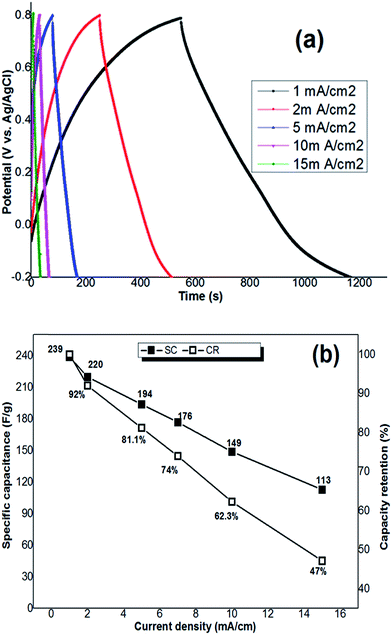
It should be noted that the supercapacitive performance of hydrohausmannite has been rarely reported and only one work has been performed in this regard. Yan et al.9 investigated the electrochemical performance of the hydrohausmannite nanoplates prepared by hydrothermal method. Electrochemical tests via cyclic voltammetry and charge–discharge revealed that the nanoplates are capable to deliver a specific capacitance as high as 222.4 F g−1 at the applied current density of 0.1 A g−1, and also good rate capability (66.7 F g−1 at 6 A g−1) was observed. Based on the obtained results, they concluded that hydrohausmannite may have great potential applications in supercapacitor electrode material. However, to be able to judge the results of this work and the properties of the product, the electrochemical properties of the prepared nanostructured hydrohausmannite were investigated by cyclic voltammetry and galvanostatic charge–discharge measurements. The electrodeposited nanoplates possess an specific capacitance as high as 239 F g−1 calculated from discharge curve with current density 1 mA cm−2, and the capacity retentions of 92%, 81%, 74%, 62% and 47% at the applied current densities of 2, 5, 7, 10 and 15 mA cm−2, respectively, as compared to the low applied current density of 1 mA cm−2. These values implied that the prepared sample exhibits good cycling and rate capability as active electrode material for supercapacitor. Furthermore, comparing the obtained results with the electrochemical performances of other MnOx or MnOOH capacitor materials confirmed that the hydrohausmannite nanoplates have good electrochemical properties which make them as a potential candidate for use in supercapacitors.
2 Experimental section
2.1 Chemicals
MnCl2·6H2O (Merck), polytetrafluoroethylene (PTFE, Merck), carbon black and Na2SO4 (Merck) were used as received. All solutions were prepared using water purified by a UHQ Elga System. An aqueous solution of 5 mM MnCl2·6H2O was prepared for electrodeposition.2.2 Preparation procedure
Hydrohausmannite was prepared by a novel one step cathodic electrodeposition method as below. The deposition experiments were performed in a two electrode electrochemical cell including a steel (316L) cathode and graphite anode. An aqueous 0.005 M MnCl2·6H2O solution was used as the electrolyte. A direct current (DC) regime (I = 2 mA cm−2) was applied in the deposition process. The deposition time and bath temperature were 30 min and 25 °C, respectively. Prior to each deposition, the steel substrate was given a galvanostatically electropolishing. The deposition experiments were performed using an electrochemical workstation system (Potentiostat/Galvanostat, Model: NCF-PGS 2012, Iran). After the deposition, the steel substrates were repeatedly rinsed with water and then dried at RT for 5 h. Finally the deposits were scraped from the substrates and evaluated by further analyses.2.3 Characterization
The phase composition and structure of the prepared samples were investigated by powder X-ray diffraction (XRD) using a Phillips PW-1800 diffractometer with a Cu Kα radiation source in 2θ values ranging from 5 to 70 °C at a scanning rate of 5 degree per min. The FTIR spectra of the samples were obtained using a Bruker Vector 22 Fourier transformed infrared spectroscope in the range of 400–4000 cm−1. The samples were prepared in a KBr wafer and the analyses were performed at ambient temperature. Each FTIR spectrum was acquired after 20 scans at a resolution of 4 cm−1 from 400 to 4000 cm−1. The morphologies of the prepared hydrohausmannite powder were studied using a scanning electron microscope (SEM, LEO 1455 VP, Oxford, UK, operating voltage 30 kV). Transmission electron microscopy (TEM) images were also acquired using a Phillips EM 208 transmission electron microscope with an accelerating voltage of 100 kV.2.4 Electrochemical measurements
The working electrodes were fabricated by mixing the prepared hydrohausmannite powder (80 wt%), carbon black (15 wt%) and polytetrafluorene ethylene (PTFE, 5 wt%). Next a small amount of ethanol was added to the mixture to produce a homogeneous paste and the mixture was pressed onto steel grid (surface area = 1 cm2) current collectors to form the working electrodes. The electrochemical performances of the prepared working electrodes were performed in a conventional three electrode cell filled with a 1 M Na2SO4 solution as the electrolyte. A platinum foil and an Ag/AgCl (saturated with 1 M KCl) electrode were used as the counter and reference electrodes, respectively. For the electrochemical measurements, a homemade potentiostat according to our previous works22,23 was used. The cyclic voltammetric (CV) studies were conducted in a potential range of between −0.2 and 0.8 V versus Ag/AgCl at various scan rates of 5, 10, 20, 50, 100 and 125 mV s−1. The constant current charge–discharge tests were carried out at different current densities of 1, 2, 5, 10 and 15 mA cm−2 within a potential range of −0.2 to 0.8 V versus Ag/AgCl reference electrode.3 Results and discussion
3.1 Structural characterization
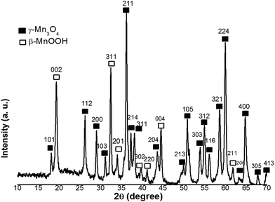
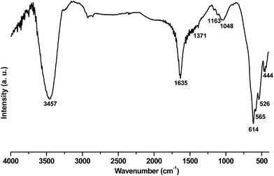
Fig. 1 shows the XRD pattern of the sample prepared in the electrodeposition process. All peaks of the pattern can be well indexed to feitknechtite (β-MnOOH, JCPDS No. 18-0804) and hausmannite (γ-Mn3O4, JCPDS No. 80-0382)with a = 0.576 nm and c = 0.947 nm, as donated by symbols in the pattern. This mixed phases was previously recognized as pure single phase i.e. hydrohausmannite.6–8 No peak, related to any impurities, was observed in the XRD pattern, which confirmed that a pure hydrohausmannite phase is prepared by our used method.In order to gain information on the chemical bonds present in the electrodeposited powder, FT-IR studies were carried out in the wavelength range of 400–4000 cm−1. Fig. 2 illustrates FT-IR spectrum of the prepared sample. The bands at 3457 and 1635 cm−1 were to the stretching vibration of –OH and the bending vibrations of water molecules. The bands between 800 and 1400 cm−1 (i.e. 1371, 1163, 1048 and 843 cm−1) are typically attributed to the bending vibrations of –OH groups bound with Mn atoms.24 The peaks in the range of 400–800 cm−1 were also indicative of the existence of octahedral MnO6.25 The two major peaks at 614 and 526 cm−1, were assigned to the coupling between the Mn–O stretching modes of tetrahedral and octahedral sites of Mn3O4, respectively.25,26 The shoulder peak at 565 cm−1 and a major one at 444 cm−1 were also assigned to the stretching modes of Mn–O in MnOOH.27 Based on these results, the IR analysis reconfirmed the formation of mixed Mn3O4 and MnOOH phases (i.e. hydrohausmannite), which was in accordance with XRD results (Fig. 1).
3.2 Morphological characterization
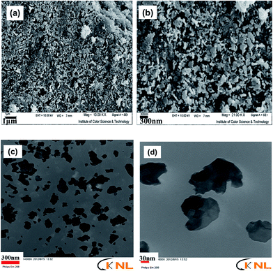
Morphological characteristics of the sample are shown in the SEM images in Fig. 3, which show that the sample is composed of both particle- and plate-like structures. In fact, a major portion of the prepared hydrohausmannite was found to have plate-like structures, while the rest had particle morphology. These observations were in good agreements with those in previous reports,6–8 which stated that hexagonal plates and particles in hydrohausmannite are generally recognized as β-MnOOH and γ-Mn3O4, respectively.7 So, based on this fact and the SEM results, it can be restated that the sample is composed of two MnOOH and γ-Mn3O4 phases which is the characteristic of hydrohausmannite. However, since Da et al. have previously reported that γ-Mn3O4 and β-MnOOH in hydrohausmannite could not be simply recognized based on morphological conclusions, further examinations were conducted.8 TEM images in Fig. 3c and d also show large portions of plate-like and less quantities of particles for the prepared sample. However, as seen in Fig. 3d, the plates did not possess complete hexagonal shapes since their edges were irregular. Eventually it was concluded that the prepared hydrohausmannite possessed both plate- and particle-like morphologies.3.3 Mechanism of formation
Formation of the hydrohausmannite deposit on the cathode surface, from the chloride bath can be probably be explained on the based on a two-step electrochemical–chemical (EC) mechanism14,15 as shown in Fig. 4, which includes: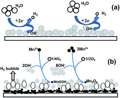 | ||
| Fig. 4 Schematic view of the proposed mechanism for hydrohausmannite formation via the cathodic electrodeposition; (a) electrochemical and (b) chemical steps. | ||
The electrochemical step:
| O2 + 2H2O + 4e− → 4OH− E° = +0.26 V vs. Ag/AgCl | (1-1) |
| 2H2O + 2e− → H2 + 2OH− E° = −1.08 V vs. Ag/AgCl | (1-2) |
The chemical step:
| Mn2+(aq) + 2OH−(aq) + ¼O2 → MnOOH + ½H2O | (2) |
| 3Mn2+(aq) + 6OH−(aq) + ½O2 → Mn3O4 + 3H2O | (3) |
A schematic illustration of these electrochemical and chemical steps is shown in Fig. 4. Considering the value of the observed potential (−1.07 V vs. Ag/AgCl) during the deposition process, as suggested in the proposed mechanism, the reduction of water (eqn (1-2)) has a major role in the electrogeneration of base at the applied conditions. In fact, the electrochemical step precedes reactions (1-2) during the deposition process as schematically shown in Fig. 4a. Furthermore, the flow of gas bubbles was observed on the cathode surface throughout the deposition step, which further confirmed the electrogeneration of OH− ions due to the electrolysis of water. H2 bubbles can also affect the surface morphology of the deposit and also act as a dynamic template for the formation and the growth of deposit.28 In the chemical step, Mn2+ cations can react with the OH− ions produced on electrochemical step in two different ways, which can result in the formation of MnOOH (eqn (2)) and Mn3O4 (eqn (3)) deposits, as schematically shown in Fig. 4b. For the formation of hydrohausmannite on the cathode surface, the chemical step should be proceeded via both mentioned ways (eqn (1-1) and (1-2)). Notably, the composition of the deposited sample (i.e. Mn3O4 to MnOOH ratio) is directly related to the rates of (2) and (3) reactions. And morphology of the deposit is also dedicated by these reactions (i.e. rates of formation and growth steps).
3.4 Electrochemical evaluation
In order to explore the electrochemical properties of the working electrode fabricated using the deposited hydrohausmannite, cyclic voltammetry (CV) at various scan rates within an electrochemical window from −0.2 V to 0.8 V, was carried out and the corresponding CV curves are shown in Fig. 5a. Obviously, the CV curves of hydrohausmannite show some derivation from a rectangular shape even at low san rate of 5 mV s−1, indicating the pseudocapacitance behavior of the fabricated electrode. Notably, the mechanism of supercapacitive performance of hydrohausmannite has not been reported so far, and there is only one report on the electrochemical performance of hydrohausmannite,9 where it has been reported that hexagonal hydrohausmannite plates prepared via a hydrothermal method are capable of delivering a high specific capacitance (222.4 F g−1 at 0.1 A g−1) and good rate capability (66.7 F g−1 at 6 A g−1), which has been attributed to their hexagonal structure. Also, it has been observed that the performance becomes even better after cycling, due to the formation of birnessite. However, the charge–discharge process of hydrohausmannite has been not described yet. The pseudocapacitance behavior of hydrohausmannite in presence of Na2SO4 can be explained based on the following mechanism: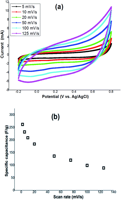 | ||
| Fig. 5 (a) Cyclic voltammograms of the prepared electrode at various scan rates, and (b) the observed specific capacitance versus scan rates of 2 to 100 mV s−1. | ||
For Mn3O4 species:28,29
| Mn3O4 + δNa+ + δe− + H2O → NaδMnOx·nH2O | (4) |
| NaδMnOx·nH2O + yH+ + zNa+ + (y + z)e− ↔ Naδ+zMnOx·nH2O | (5) |
For MnOOH species:30,31
| MnOOH ↔ MnO2 + H+ + e− | (6) |
| MnO2 + Na+ + e− ↔ MnOOH | (7) |
The nano-particle/plate morphology of the prepared hydrohausmannite can greatly reduce the diffusion length throughout the active materials, where Na+ must transfer during the charge/discharge process. These characteristics can also provide the electrochemical better utilization of Mn3O4 and MnOOH. The specific capacitance values can be calculated by integrating the area of the CV curves as follows:
 | (8) |
The dependence of the calculated capacitance on the scan rate of CV from 5 to 125 mV s−1 is shown in Fig. 5b. Based on the proposed mechanism, it can be said that increasing the scan rate has a direct impact on the diffusion of Na+ into the hydrohausmannite matrix. At low scan rates (e.g. 5 mV s−1), the reactions of 4 and 6 will have enough time to proceed, and Na+ can also easily diffuse into almost all available materials of the electrode, leading to a complete insertion reaction in eqn (5) and (7), and hence a better capacitive performance, where a high value of specific capacitance (232 F g−1) is observed. However, increasing the scan rate has a direct impact on the progress of reactions and the diffusion of Na+ into the hydrohausmannite and also the observed capacitance as seen in Fig. 5b. At a high scan rate (125 mV s−1), reactions (4) and (6) will not have enough time to develop, and further Na+ will only approach the outer surface of the electrode. Hence due to the great reduction of effective interactions among the ions and the electrode, the capacity loss becomes relatively high (Fig. 5b). However, the prepared hydrohausmannite revealed to be capable of exhibiting a good electrochemical performance i.e. 89 F g−1 at the high scan rate of 125 mV s−1.
The galvanostatic technology is a reliable experiment to evaluate the specific capacitance values. Fig. 6 shows the charge–discharge curves of Mn3O4 nanorods at the current densities of 1, 2, 3, 5, 10 and 15 A g−1. The specific capacitance (SC) of the Mn3O4 electrode can be calculated according to the following equation:
 | (9) |
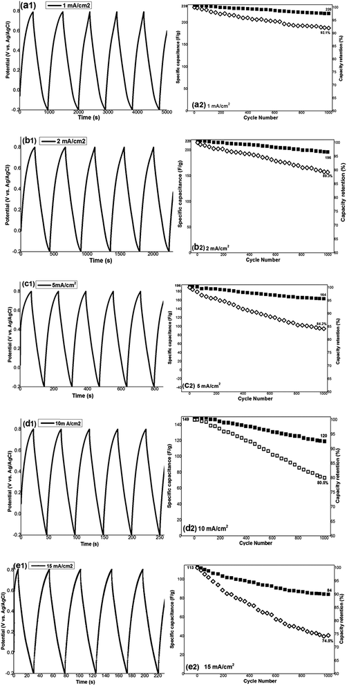
To investigate the cyclability, the working electrode was cycled (1000 cycling) at the different current densities, and the results for the first 5 cycles of each applied current density are shown in Fig. 7(a1–d1). A little variation from linear shape of potential during both charging and discharging processes was observed, indicating the pseudocapacitance performance of the prepared electrode. The specific capacitance of each cycle at the applied current density was calculated using eqn (8), and is shown in Fig. 7(a2–d2). Also based on the obtained capacitance values, the capacity retention of the fabricated electrode on cycling was evaluated and depicted against cycle number in Fig. 7(a2–d2). The results showed that hydrohausmannite reveals highly stable capacitance behaviours during cycling where high capacity retentions of 91.1%, 89.3%, 84.2%, 80.5% and 74.5% where observed after 1000 charge–discharge cycles at the current densities of 1, 2, 5, 10 and 15 mA cm−2, respectively (Fig. 7(a2–e2)). These results confirmed the excellent supercapacitive performance of the prepared hydrohausmannite.
4 Conclusion
For the first time, hydrohausmannite was prepared through a galvanostatic cathodic electrodeposition procedure, from aqueous MnCl2 solution. The electrochemical measurements by cyclic voltammetry and charge–discharge techniques revealed the produced nanostructures to have excellent pseudocapacitive behaviors of high specific capacitances and stable cycle life at various applied current densities. The results marked hydrohausmannite as a potential candidate for use as the electrode material in supercapacitors, and also introduce cathodic electrodeposition as a method that can be used for the preparation of hydrohausmannite under simple operating conditions.References
- P. Simon and Y. Gogotsi, Nat. Mater., 2008, 7, 845–854 CrossRef CAS PubMed.
- C. Liu, Z. Yu, D. Neff, A. Zhamu and B. Z. Jang, Nano Lett., 2010, 10, 4863–4868 CrossRef CAS PubMed.
- L. Wang, Y. Li, Z. Han, L. Chen, B. Qian, X. Jiang, J. Pinto and G. Yang, J. Mater. Chem. A, 2013, 1, 8385–8397 CAS.
- D.-Y. Youn, H. L. Tuller, T.-S. Hyun, D.-K. Choi and I.-D. Kim, J. Electrochem. Soc., 2011, 158, A970–A975 CrossRef CAS.
- Z. Liu, Y. Xing, S. Fang, X. Qu, D. Wu, A. Zhang and B. Xu, RSC Adv., 2015, 5, 54867–54872 RSC.
- W. Feitknecht and W. Marti, Helv. Chim. Acta, 1945, 28, 129–147 CrossRef CAS.
- O. Bricker, Am. Mineral., 1965, 50, 1296–1354 CAS.
- D. Yan, Y. Li, Y. Liu, R. Zhuo, Z. Wu and J. Wang, Appl. Mech. Mater., 2014, 513, 277–280 Search PubMed.
- D. Yan, Y. Li, Y. Liu, R. Zhuo, Z. Wu, B. Geng, J. Wang, P. Ren, P. Yan and Z. Geng, Mater. Lett., 2014, 117, 62–65 CrossRef CAS.
- B. G. Choi, Y. S. Huh, W. H. Hong, H. J. Kim and H. S. Park, Nanoscale, 2012, 4, 5394–5400 RSC.
- A. Biswal, B. C. Tripathy, K. Sanjay, T. Subbaiahbcd and M. Minakshi, RSC Adv., 2015, 5, 58255–58283 RSC.
- G.-R. Li, H. Xu, X.-F. Lu, J.-X. Feng, Y.-X. Tong and C.-Y. Su, Nanoscale, 2013, 5, 4056–4069 RSC.
- P. Si, P. Chen and D.-H. Kim, J. Mater. Chem. B, 2013, 1, 2696–2700 RSC.
- T. Yousefi, A. Nozad Golikand, M. H. Mashhadizadeh and M. Aghazadeh, J. Taiwan Inst. Chem. Eng., 2012, 43, 614–618 CrossRef CAS.
- T. Yousefi, A. Nozad Golikand, M. H. Mashhadizadeh and M. Aghazadeh, Curr. Appl. Phys., 2012, 12, 544–549 CrossRef.
- Z. Gui, E. Gillette, J. Duay, J. Hu, N. Kim and S. B. Lee, Phys. Chem. Chem. Phys., 2015, 17, 15173–15180 RSC.
- A. Biswal, B. C. Tripathy, D. Li and M. Minakshi, Dalton Trans., 2015, 44, 16446–16457 RSC.
- Z. Sun, S. Firdoz, E. Ying-Xuan Yap, L. Li and X. Lu, Nanoscale, 2013, 5, 4379–4387 RSC.
- Y. Qiu, P. Xu, B. Guo, Z. Cheng, H. Fan, M. Yang, X. Yang and J. Li, RSC Adv., 2014, 4, 64187–64192 RSC.
- J. Duay, E. Gillette, J. Hu and S. B. Lee, Phys. Chem. Chem. Phys., 2013, 15, 7976–7993 RSC.
- P. Yang, Y. Li, Z. Lin, Y. Ding, S. Yue, C. P. Wong, X. Cai, S. Tan and W. Mai, J. Mater. Chem. A, 2014, 2, 595–599 CAS.
- J. Shabani, A. Ehsani, A. Nikkar, P. Norouzi, M. R. Ganjali and M. Wojdyla, New J. Chem., 2015, 39, 9454–9460 RSC.
- J. Shabani, P. Norouzi and M. R. Ganjali, RSC Adv., 2015, 5, 20446–20452 RSC.
- Z. Liu, Y. Xing, S. Fang, X. Qu, D. Wu, A. Zhang and B. Xu, RSC Adv., 2015, 5, 54867–54872 RSC.
- W. Zhang, Z. Yang, Y. Liu, S. Tang, X. Han and M. Chen, J. Cryst. Growth, 2004, 263, 394–399 CrossRef CAS.
- Y. Li and X. M. Li, RSC Adv., 2013, 3, 2398–2403 RSC.
- Z. Li, H. Bao, X. Miao and X. Chen, J. Colloid Interface Sci., 2011, 357, 286–291 CrossRef CAS PubMed.
- F. Khosrow-pour, M. Aghazadeh and B. Arhami, J. Electrochem. Soc., 2013, 160, D150–D155 CrossRef CAS.
- Y. Dai, K. Wang and J. Xie, Appl. Phys. Lett., 2007, 90, 104102–104103 CrossRef.
- D. P. Dubal, D. S. Dhawale, R. R. Salunkhe and C. D. Lokhande, J. Electroanal. Chem., 2010, 647, 60–65 CrossRef CAS.
- S. Devaraj and N. Munichandraiah, J. Phys. Chem. C, 2008, 112, 4406–4417 CAS.
- W. Xiao, H. Xia, J. Y. H. Fuh and L. Lu, J. Power Sources, 2009, 193, 935–938 CrossRef CAS.
- T. Yousefi, A. N. Golikand, M. H. Mashhadizadeh and M. Aghazadeh, Curr. Appl. Phys., 2012, 12, 193–198 CrossRef.
- T. Yousefi, A. N. Golikand, M. H. Mashhadizadeh and M. Aghazadeh, J. Solid State Chem., 2012, 190, 202–207 CrossRef CAS.
- H. Fang, S. Zhang, X. Wu, W. Liu, B. Wen, Z. Du and T. Jiang, J. Power Sources, 2013, 235, 95–104 CrossRef CAS.
- P. Lv, P. Zhang, Y. Feng, Y. Li and W. Feng, Electrochim. Acta, 2012, 78, 515–523 CrossRef CAS.
- S. Zhao, T. Liu, D. Shi, Y. Zhang, W. Zeng, T. Li and B. Miao, Appl. Surf. Sci., 2015, 351, 862–868 CrossRef CAS.
- W. Li, J. Shao, Q. Liu, X. Liu, X. Zhou and J. Hu, Electrochim. Acta, 2015, 157, 108–114 CrossRef CAS.
- Y. Cheng, S. Lu, H. Zhang, C. V. Varanasi and J. Liu, Nano Lett., 2012, 12, 4206–4211 CrossRef CAS PubMed.
| This journal is © The Royal Society of Chemistry 2016 |

