DOI:
10.1039/C5RA19844E
(Paper)
RSC Adv., 2016,
6, 641-647
A scandium-doped manganate anode for a proton-conducting solid oxide steam electrolyzer†
Received
25th September 2015
, Accepted 24th November 2015
First published on 1st December 2015
Abstract
Perovskite La0.8Sr0.2MnO3−δ is widely used as an anode for proton-conducting solid oxide steam electrolyzers; however, the insufficient electro-catalytic activity still restricts the electrochemical steam oxidation activity. In this work, catalytically-active scandium is doped into the B-site of the manganate La0.8Sr0.2Mn1−xScxO3−δ (x = 0–0.1) to enhance the electrocatalytic performance. Combined characterizations of XRD, TEM, XPS, SEM and EDS confirm the successful partial replacement of Mn by Sc in the B-site. The doping of Sc remarkably improves ionic conductivity while accordingly decreases electronic conductivity. The electrocatalytic activity has been greatly improved and the composition of La0.8Sr0.2Mn1−xScxO3−δ with x = 0.05 has demonstrated the best electrode polarization performance. The faradic efficiency is significantly enhanced to as high as 80% for La0.8Sr0.2Mn1−xScxO3−δ (x = 0.05) in a proton conducting solid oxide electrolyzer in contrast to a cell with traditional LSM anode for high temperature steam electrolysis.
Introduction
Solid oxide electrolyzers have demonstrated tremendous advantages for the efficient electrochemical conversion of steam into hydrogen using renewable electrical energy.1–4 Proton-conducting solid oxide electrolyzers can efficiently electrolyze steam and separately produce hydrogen at the anode and oxygen at the cathode under external loaded voltages.5–7
Strontium-doped LaMnO3 (LSM) is a typical p-type electronic conductor with a reasonable conductivity in a wide range of oxygen partial pressures. The valence change of Mn in the B-site provides oxygen vacancies and strontium doping further improves the electrical properties.8,9 LSM is commonly used as an air electrode for oxygen reduction in fuel cell mode or for oxygen evolution in electrolysis cell mode.10–12 In our previous work, a faradic efficiency with approximately 45% has been achieved for steam electrolysis with bare LSM anode in a proton conducting solid oxide electrolyzer at 800 °C. The limited electro-catalytic activity of LSM restricts the electrochemical steam oxidation in the anode compartment.13 To improve anode activity, catalytically-active Co3O4 and Fe2O3 nanoparticles have been loaded via impregnation method; however, the agglomeration of nanoparticles has been observed though the faradic current efficiency is enhanced as reported in our previous work.14
Scandium oxides have been commonly considered as an efficient electro-catalyst and loaded in composite electrodes to enhance electro-catalytic activity.15,16 The scandium is widely doped into perovskite electrode materials to improve electro-catalytic performance. The scandium dopant in perovskite oxide like BSCF normally produces oxygen vacancies by the partial reduction of B-site element in crystal structure. Shao et al. reported that the improved electrode performance is attributed to the generation of oxygen vacancies that reduce oxygen migration energy at electrode/electrolyte interface region.17 However, the electronic conductivity gradually decreases with increasing scandium doping concentration though the oxidation/reduction kinetics of composite electrode is improved as reported by Irvine et al.18 Cheng et al. reported that the scandium-doped manganate cathode exhibits 1.4 W cm−2 for a solid oxide fuel cell with humidified hydrogen fuel at 800 °C, which can be ascribed to the generation of oxygen vacancy that improves electrode activity in manganate.19 Moreover, substitution of only a small amount of scandium is already beneficial to the improvement of electrode performance, which is because of the unique properties of scandium that benefits electrocatalytic activity. Our previous work has also demonstrated that the ionic conductivity of Sc-doped LSCM is improved by 10 times while the electronic conductivity decreases in contrast to the conductivity of bare LSCM.20,21
In this work, scandium is doped into the B-site of LSM anode to improve the electro-catalytic activity. The crystal structure, oxygen nonstoichiometry and electrical properties of Sc-doped LSM are systematically studied. The dependence of electrochemical performance on the electrical properties of doped LSM is investigated. Steam electrolysis is performed with Sc-doped LSM anode in a proton conducting solid oxide electrolyzer at 700 °C.
Experimental
All the chemical reagents were purchased from SINOPHARM Chemical Reagent Co., Ltd (China) unless specified otherwise. The synthesis of La0.8Sr0.2Mn1−xScxO3−δ (LSMSx, x = 0, 0.02, 0.05, 0.08 and 0.1) was carried out using a solid-state reaction method.22,23 The electrolyte BaCe0.5Zr0.3Y0.16Zn0.04O3−δ (BCZYZ) powder was synthesized using a solid-state reaction method as reported elsewhere.24 A 2 mm-thick BCZYZ electrolyte was prepared by dry-pressing the BCZYZ powders into a green disk in a diameter of 20 mm followed by a sintering at 1400 °C for 10 h. XRD (CuKα, 3° min−1, 2θ = 10–90°, D/MAX2500V, Rigaku, Japan) was used to identify the phase formations of electrode and electrolyte materials. High-resolution transmission electron microscope (HR-TEM, 200 kV, JEM-2100F, JEOL Ltd, Japan) was used to investigate the microstructures of LSM and LSMS0.05. X-ray photoelectron spectroscopy (XPS; Al Kα, ESCALAB25, Thermo, America) were employed to characterize the valence states of the elements in electrode materials before and after reduction in 5% H2/Ar at 800 °C for 30 min. All XPS results are fitted with a Shirley-type background subtraction method. The background-functions for different spectroscopies of elements are fitted by 80% Gaussian and 20% Lorentz. Thermogravimetric analysis (TGA, 5 °C min−1, STA449F3, Germany) of the oxidized LSM, LSMS0.05 and LSMS0.1 samples was conducted in 5% H2/Ar (30 ml min−1) and the temperature at 800 °C was stabilized for 30 min before cooling down to room temperature.
About 2.0 g of LSMSx (x = 0, 0.02, 0.05, 0.08 and 0.1) powders were pressed into bars, respectively, then, sintered in air at 1400 °C to obtain samples for mixed conductivity measurements. The conductivities of the samples were tested from room temperature to 700 °C in air using the DC four-terminal method with an online system with multi-meter (Keithley 2000, Keithley Instruments Inc., USA). The dependence of conductivity on oxygen partial pressure (pO2) (0.2–10−18 atm) was recorded using an online oxygen sensor (Type 1231, Novatech, Australia). The ionic conductivity of samples was tested versus temperature using the electron-blocking electrode method.25–27 The LSMSx composite anode slurry was prepared by milling the BCZYZ powders with LSMSx powders at a 40
:
60 weight ratio in alpha-terpineol with 5% cellulose additive. The La0.75Sr0.25Cr0.5Mn0.5O3−δ (LSCM) composite cathode slurry was prepared in a similar way. The electrode slurries were printed onto the electrolyte in an area of 1 cm2 followed by a heat treatment at 1100 °C for 3 h in air to assemble a single cell or a symmetric cell. The current-collection layer was prepared using silver paste (SS-8060, Xinluyi, Shanghai, China). Scanning electron microscopy (SEM) (1.0 kV, ×2000, SU8020, Japan) was employed to observe the cross-section views of symmetric cells and single cells.
The AC impedance spectroscopy of the symmetric cells was recorded at 700 °C with the electrodes exposed to different oxygen partial pressures using an electrochemical station (IM6, Zahner, Germany). The frequency range of 4 M to 0.1 Hz and a current strength of 10 mA in two-electrode mode. The electrode polarization resistance was calculated by modelling the spectra using the Zview software as presented in ESI (Fig. S1†). For electrochemical measurements, the single electrolyzer was sealed on a home-made testing jig using ceramic paste (JD-767, Jiudian, Dongguan, China). The cell structure, parameters, electrode reactions and testing schematic were shown in Fig. S2.† The electrolyzers were typically tested at 700 °C with cathode fed with 5% H2/Ar (30 ml min−1) and anode fed with 5% H2O/air (30 ml min−1), respectively. The AC impedance spectroscopy and current–voltage curve (I–V curve) of the electrolyzers were recorded with the electrochemical station. The output gas from LSCM cathode was detected using an online gas chromatograph (GC9790II, Fuli, Zhejiang, China) to analyse hydrogen concentrations.
Results and discussion
3.1 Structure
Fig. 1(a1–a5) shows the XRD Rietveld refinement patterns of the single-phase perovskite-type LSMSx (x = 0, 0.02, 0.05, 0.08 and 0.1) (LSM: PDF#86-1233), which reveals the successful partial replacement of Mn by Sc in the B-site of LSMSx.14 The structures of LSMSx are monocline with space group of R
C. The refinements of the oxidized samples give chi2, wRp and Rp values as 1.0–1.5, 7–8.5%, 5.5–6.5%, respectively. Fig. 1(b) shows the parameters for LSMSx (x = 0, 0.02, 0.05, 0.08 and 0.1) calculated from XRD data. The incorporation of Sc3+ increases cell volumes from 350.685 to 355.637 Å3, which is because of the larger ionic radii of Sc3+ (0.745 Å) compared with that of Mn3+ (0.645 Å) and Mn4+ (0.53 Å) with the same coordination numbers. The doping of Sc has definitely caused the lattice expansion; however, the catalytic activity is not only related to lattice change but more in relation to the Sc element itself. The almost linear lattice expansion indicates the solution limit of Sc is above 0.1 in the B site of LSM. As shown in Fig. S3(a) and (b),† the selected area high-resolution transmission electron microscopy (HR-TEM) analysis demonstrates the crystalline feature of the oxidized LSM and LSMS0.05 samples. The lattice spacing of (110), (134) and (110) are determined as 2.82, 1.26 and 2.91 Å, respectively. The spacing of (110) increases from 2.82 to 2.91 Å when the proportion of Sc reaches x = 0.05 which firmly confirms the lattice expansion caused by doping scandium as already determined by the XRD.
 |
| Fig. 1 XRD Rietveld refinement patterns of the oxidized (a1–a5) LSM1−xSx powder samples with x = 0, 0.02, 0.05, 0.08 and 0.1; (b) cell parameters of the oxidized LSM1−xSx powder samples with x = 0, 0.02, 0.05, 0.08 and 0.1. | |
3.2 Oxide vacancies
To confirm the elemental valence change, XPS spectra are obtained as core level spectroscopies for Sc-2p, Mn-2p and O-1s of the oxidized and reduced LSM and LSMS0.05. As shown in Fig. S3(a1) and (a2),† both Mn4+ and Mn3+ are observed in the oxidized LSM sample; however, the proportion of Mn4+ is changing smaller because of the reduction of Mn4+ to Mn3+ by treating LSM samples in a reducing atmosphere.13,20 Similar change of chemical state of Mn element is also observed in the LSMS sample before and after reduction at high temperatures, as shown in Fig. 2(a1) and (a2). The O-1s XPS spectra of LSM and LSMS0.05 shown in Fig. 3 and 4 are observed at 529.0 and 531.2 eV for oxidized samples and 528.9 and 530.9 eV for reduced samples.28 As shown in Fig. 2(b1) and (b2), only Sc3+ occurs in oxidized and reduced samples. The Sc3+ (2p1/2) shows peaks at 406.1 and 405.1 eV while and Sc3+ (2p3/2) demonstrates signals at 402.90 and 401.40 eV in the oxidized samples.29,30
 |
| Fig. 2 XPS result of Mn (a1), Sc (b1), O (c1) in the oxidized LSMS0.05; Mn (a2), Sc (b2); O (c2) in the reduced LSMS0.05. | |
 |
| Fig. 3 TGA test of oxidized LSM (a), LSMS0.05 (b), LSMS0.1 (c) in 5% H2/Ar from 20 °C to 800 °C at the rate of 5 °C min−1; (d) the XRD patterns for the powder samples after TGA test. | |
 |
| Fig. 4 (a) The mixed conductivity of LSM1−xSx versus temperature in air; (b) the mixed conductivity of LSM1−xSx versus oxygen partial pressure (from 10−18 to 0.2 atm) at 700 °C; (c) the ionic conductivity of LSM1−xSx versus temperature in air; (d) the ionic conductivity of LSM1−xSx with x = 0, 0.02, 0.05, 0.08 and 0.1 in air at 700 °C. | |
The introduction of Sc is expected to create oxygen vacancy that is strongly in relation with the amount of low-valence ions at the B-sites. The defect chemistry is demonstrate in the form of defect reaction as shown in Fig. S5.† The doping of Sc is expected to definitely cause the change of nonstoichiometry. Thermogravimetry analysis (TGA) is then employed to analyze the oxygen nonstoichiometry of the doped samples. TGA is commonly used to analyse the oxygen nonstoichiometry.11,12,18,21 It is found that the fixed-valence Sc significantly reduces the oxygen storage capacity in redox cycles. As observed in Fig. 3(a), the oxidized LSM exhibits a 3.96% weight loss when heated to 800 °C in a reducing gas because of the reduction of Mn4+ to Mn3+, implying that the oxygen loss is 0.54 per chemical formula of LSM. The calculation method is shown in Fig. S6.† The reduction treatment offers sufficient oxygen vacancies as the charge carriers for oxide-ion conduction. In contrast, the weight loss are reduced to 3.25% and 2.34% for LSMS0.05 and LSMS0.1, respectively, indicating the oxygen loss of 0.42 and 0.28 per chemical formula as shown in Fig. 3(b) and (c), which suggests that the oxygen vacancy is strongly dependent on the Sc doping concentration. As shown in Fig. 3(d), XRD is used to characterize the LSM, LSMS0.05 and LSMS0.1 after TGA tests. It is found that these doped materials still remain pure perovskite structure though slight XRD peak shift is observed because of the lattice expansion upon reduction.
3.3 Conductivity
The dependence of the mixed conductivity on temperature and on oxygen partial pressure was investigated as shown in Fig. 4. Fig. 4(a) shows the dependence of mixed conductivity of LSMSx on temperature (200–700 °C) in air. The samples present typical p-type conducting behaviors with positive temperature coefficients. The LSM sample without Sc doping exhibits the highest total conductivity of approximately 50 S cm−1 at 700 °C. A mechanism of the Zerner double exchange process is usually proposed in perovskite oxides, in which electrons hop between B-site lattice cations through strongly overlapping B–O–B bonds and can create electronic conduction. As for LSMSx, polaron hopping occurs mainly through the Mn3+–O2−–Mn4+ bond and the Sc3+ with a fixed oxidation state replaces Mn ions in B-site and blocks electron hopping, which leads to the decrease of electronic conductivity. Therefore, the mixed conductivity gradually decreases to 24.25 S cm−1 for the LSMS0.1 with the maximum Sc content of x = 0.1. Fig. 4(b) shows the dependence of mixed conductivity of LSMSx on the oxygen partial pressure. Reducing oxygen partial pressure leads to the decrease of electronic conductivity because of the increase of oxygen vacancies, which further confirms the p-type conduction properties. The oxide-ion conductivity of LSMSx was tested using electron-blocking electrode method.25–27 The sample pellets were put between two dense YSZ pellets with Ag slurry pasted between the interfaces. The Ag paste is printed on the opposite surfaces of the YSZ pellets as current collectors to assemble the samples for the ionic conductivity measurement. In the system, the electron flux is blocked by YSZ layer because YSZ is considered as a pure oxygen ion conductor. Applying a DC voltage, a stable current is observed at a designated temperature. The transformation between oxygen molecular and oxygen ion is repeated on Ag electrode for several times in the testing system. The resistance of YSZ disc with Ag layer is measured before the measurement of the cell with electron-blocking electrode. The ionic conductivities of samples are calculated by subtracting the resistance of YSZ disc with Ag layer. Fig. 4(c) shows the temperature dependence of ionic conductivity of LSMSx (x = 0, 0.02, 0.05, 0.08 and 0.1) in air (500–700 °C). The ionic conductivities of the oxidized samples improve with temperature and finally reach 5.0 × 10⁻⁴, 1.8 × 10⁻³, 2.0 × 10⁻², 3.6 × 10⁻³ and 3.2 × 10⁻³ S cm−1 for the samples with x = 0, 0.02, 0.05, 0.08 and 0.1, respectively, as shown in Fig. 4(d). And the LSMS0.05 demonstrates the highest ionic conductivity, which indicates the optimum oxygen vacancy contents. The oxygen migration energy is expected to be lower, but when concentration reaches a certain value, oxygen vacancies will agglomerate which produces a negative influence on ionic conductivity.31–34 It can be observed that the ionic conductivity is more dependent on the Sc doping in contrast to temperature (600–700 °C), which indicates that the doping of Sc is more effective to enhance the ionic conduction.
3.4 Symmetrical cell
Fig. S7(a) and (b)† show the microstructure of symmetric cells with LSM and LSMS0.05 electrodes, respectively. The BCZYZ electrolyte supports are uniform and dense, with the porous electrode layers strongly adhered to the electrolytes. The porous electrode layers are approximately 20 μm-thick while porous silver current collector layer is about 2 μm in thickness. As an ideal anode material for electrolyzer, the material needs to have high activity for oxygen evolution reaction involved all the steps related.14 In order to evaluate the electrochemical performance of the LSMSx electrode, AC impedance measurements of symmetric cells with LSMSx electrodes were tested under a series of oxygen partial pressures (1, 2, 5, 10 and 20% atm) at 700 °C as shown in Fig. 5. The impedance plots show two intercepts with the real axis, where the series resistance of the cell (Rs) corresponds to the first intercept and the difference between the two intercepts is a measure of the electrode polarization resistance (Rp). The impedance data was modelled using a Zview software and the equivalent circuit was shown in Fig. S1.† However, the Rs is set to 0 in order to compare the Rp for different electrodes. The proton resistance of the 2 mm-thick BCZYZ electrolyte is the primary contributor to the Rs, which gradually decreases with the oxygen partial pressure up to 20%, demonstrating that BCZYZ is a mixed conductor with a typical p-type conduction in air.35,36 The Rp of the cells indicates the polarization performances of LSMSx electrode, which is also related to the electrical properties and conducting mechanism of LSMSx ceramics. The Rp is positively dependent on the oxygen partial pressure and further improves versus increasing oxygen concentration, which is probably due to the p-type conduction of LSMSx enhanced in stronger oxidizing atmosphere under higher oxygen partial pressure.
 |
| Fig. 5 The AC impedance of symmetric cells for (a1–a5) LSM1−xSx with x = 0, 0.02, 0.05, 0.08 and 0.1 in different oxygen partial pressure at 700 °C; (b) the Rp of symmetric cells with different anodes versus oxygen partial pressure. | |
Fig. 5(a1–a5) shows the in situ AC impedance of the symmetric cells with LSMSx electrodes under different oxygen partial pressure. Fig. 5(b) shows the comparison of Rp of LSMSx in relation to oxygen partial pressures and Sc doping amounts. All the values of polarization resistances in Fig. 5(b) were calculated by the Zview software with the equivalent circuit presented in Fig. S1† as stated in our previous work.20,22–24 Higher oxygen partial pressure significantly improves the mixed conductivity that accordingly benefits the Rp, which further validates the p-type conduction mechanism of LSMSx ceramics. The Rp demonstrates the similar polarization phenomenon as the ionic conductivity as shown in Fig. 5(b). The Rp is improved versus oxygen partial pressure which indicates that the electrocatalytic activity of the composite electrode is enhanced under higher oxygen partial pressure. This is probably because of that the mixed conductivity of the electrode improves under higher oxygen partial pressure that is beneficial to the formation of hole as charge carrier. The trend of Rp value for LSMS0.05 electrode ranges from 5.02 to 1 Ω cm2 when the oxygen partial pressure increases to 0.2 atm. The LSMS0.05 electrode shows the highest ionic conductivity with the Sc doping amount of 0.05. The enhanced ionic conductivity with favourable oxygen dissociation and surface diffusion further facilitates the electrode polarizations. The doping of Sc has remarkably improved the electrode performances and the optimized Sc concentration is determined to be x = 0.05. The catalytic activity of Sc with improved ionic conductivity of LSMSx together leads to the enhanced anode activity. The FESEM images and EDS maps of composite anode based on LSMS0.05-BCZYZ are shown in Fig. S4(a) and (b),† respectively. It is observed that the elements such as Ba, Ce, Zr, Sr, Mn, especially Sc, are evenly distributed in anode, which indicates the absence of element agglomeration.
3.5 Steam electrolysis
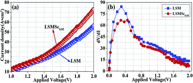
Steam electrolysis was performed in proton conducting solid oxide electrolyzers with LSM and LSMS0.05 anodes at 700 °C, respectively. Fig. 6(a) corresponds to the I–V curves of solid oxide electrolyzers with anodes in 5% H2O/air and cathode in 5% H2/Ar at 700 °C, respectively. The open circuit voltages (OCV) of the solid oxide electrolyzer reach approximately 0.517 V with the LSM anode and 0.603 V with the LSMS0.05 anode, which mainly come from the electrochemical potential (2H2 + O2 = 2H2O). The tested OCVs are lower than the theoretical value 1.2 V calculated from the Nernst equation, which is probably due the low catalytic activity of LSCM cathode. The gas leakage is not present in this work as it is repeatedly checked before and after test. The reported OCV with LSCM electrode and YSZ electrolyte is only 0.8–1.0 V at 700–900 °C, which is lower than calculated values because of the insufficient LSCM anode activity.37 In this work, the electrolyte is proton conductor with ion transference number lower than 0.8–0.9, which means the current leakage across the electrolyte. The tested OCV values are therefore only reaching 0.5–0.6 V and consistent with our reported values in work.38 The maximum current density reaches 56.59 mA cm−2 at 2.0 V with LSM anode in 5% H2O/air at 700 °C. In contrast, the current densities with LSMS0.05 anode is greatly improved to 75.07 mA cm−2 under the same conditions. In order to compare the cell resistance with two different anodes, the curves of dV/dI are presented in Fig. 6(b). The total cell resistances with LSM and LSMS0.05 anodes gradually decrease when the fuel cell mode transforms into electrolyzer mode and finally reaches 6.92 and 13.32 Ω cm2, respectively. The cell resistance with LSM0.05 is lower than that with LSM in all voltage regions, indicating the improved electrolyzer performance with LSM0.05 anode.
 |
| Fig. 6 (a) I–V curves of the two electrolyzers with different anodes at 700 °C; (b) the dV/dI (cell total resistance) of two electrolyzers with different anodes versus voltage. | |
In situ AC impedance spectroscopy is used to investigate the electrode polarizations under different applied voltages. As shown in Fig. 7, no obvious change is observed for all of the series resistances (Rs) that come from the ionic resistance of electrolyte below 1.4 V; however, the Rs slightly decreases when the applied voltages are increased from 1.6 to 2.0 V. This ohmic resistance is probably due to the contribution of the p-type conduction of the electrolyte in a less reducing atmosphere. There are two semicircles noted on the impedance spectra: the high-frequency arcs (R1) and low-frequency arcs (R2). At high frequencies, the R1 is an indication of charge transfer that is related to ionic transport. It is observed that the R1 with LSMS0.05 anodes is smaller than that of LSM, which firmly confirms the improved ionic conductivity of LSMS0.05 that significantly benefits charge transfer and accordingly reduces high frequency polarization resistances. At low frequencies, the mass transfer, R2, dominates the electrode process of the solid oxide electrolyzers, which is probably due to the dissociative adsorption, gas conversion and species transfer in the composite electrodes. The R2 is remarkably decreased for the electrolyzers with LSM and LSMS0.05 electrode at the applied voltage ranging from 1.0 to 2.0 V, suggesting the improved kinetics of gas conversion due to the electro-catalytic activity at high voltages. In the impedance spectra, the improvement of interface capacitance with LSMS0.05 anode again proves that the oxygen vacancy in LSMS0.05 electrode is beneficial to interfacial electrochemical reaction by reducing the activation energy of oxygen evolution reaction.
 |
| Fig. 7 The AC impedance of the electrolyzers based on LSM (a1 and a2) and LSMS0.05 (b1 and b2) with the flow of 5% H2O/air at 700 °C. | |
To further study electrolysis performance, both electrolyzers are fed with 5% H2O/air in anode and 5% H2/Ar in cathode at 700 °C (Fig. 8), respectively. The current densities with LSMS0.05 anode reach 5.03, 8.80, 17.2, 31.4, 47.8 and 62.8 mA cm−2 at 1.0, 1.2, 1.4, 1.6, 1.8 and 2.0 V, respectively, which are nearly 1.5 times higher than those of LSM under the same conditions. The hydrogen production rate is 0.48 ml cm−2 min−1 for the electrolyzer with LSM anode at 2.0 V; however, the hydrogen generation rates with LSMS0.05 are remarkably enhanced to as high as 0.10, 0.30, 0.59, 0.69 and 0.88 ml cm−2 min−1 at 1.2, 1.4, 1.6, 1.8 and 2.0 V, respectively. As shown in Fig. 8(a2), the faradic efficiencies are only 65% for the cell with LSM anode at 2.0 V; however, the efficiency reaches approximately 80% for the cell electrolyzer with LSMS0.05 anode at high voltages in Fig. 8(b2), which is improved by approximately 25% compared to the values with LSM anode. Faraday efficiency (also called faradaic efficiency or current efficiency) describes the efficiency with which charge (electrons) are transferred in a system facilitating an electrochemical reaction. As shown in Fig. 8(a2) and (b2), the theoretical values are 100% current efficiencies at different applied voltages. Here it should be noted that the current efficiency is commonly reported in the range of 20–60% with traditional LSM or LSCM anode for steam oxidation in proton conducting solid oxide electrolyzers.13,14,27,38,39 For most proton-type electrolyzers, the operation temperature is normally below 700–800 °C and the current efficiency is always lower for thin film cells because of the leakage of current. However, the highest current efficiency of 80% has been achieved with the modified LSMS0.05 anode for steam oxidation in our work, which further confirms the enhanced anode activity.
 |
| Fig. 8 The performances of steam electrolysis for two electrolyzers with (a1) LSM, (b1) LSMS0.05 in 5% H2O/air at 700 °C; the hydrogen production and current efficiency for the electrolyzers with the flow of 5% H2O/air (a2) LSM, (b2) LSMS0.05 at 700 °C. | |
Conclusions
In this work, rare earth element scandium is doped into the B-site of LSM to improve the electrode performance for steam electrolysis in a proton-conducting solid oxide electrolyzer. The doping of scandium remarkably improves ionic conductivity but accordingly decreases the mixed conductivity. Promising performances are obtained for the solid oxide electrolyzers with scandium-doped LSM electrodes. The anode composition with Sc concentration of 0.05 demonstrate the optimum polarization resistance of 1 Ω cm−2. At high voltage, the faradic efficiency with LSMS0.05 electrode reaches 80% which is accordingly 25% higher in contrast to the values for the electrolyzer with LSM anode at 700 °C.
Acknowledgements
This work is supported by the Natural Science Foundation of China (No. 21303037).
References
- S. S. Li, Q. Q. Qin, K. Xie, Y. Wang and Y. C. Wu, J. Mater. Chem. A, 2013, 1, 8984–8993 CAS.
- C. Jin, C. H. Yang, F. Zhao, D. A. Cui and F. L. Chen, Int. J. Hydrogen Energy, 2011, 36, 3340–3346 CrossRef CAS.
- L. M. Yang, K. Xie, S. S. Xu, T. S. Wu, Q. Zhou, T. Xie and Y. C. Wu, Dalton Trans., 2014, 3, 14147–14157 RSC.
- X. D. Yang and J. T. S. Irvine, J. Mater. Chem., 2008, 18, 2349–2354 RSC.
- T. Matzke, U. Stimming and C. Karmonik, Solid State Ionics, 1996, 86–88, 621–628 CrossRef CAS.
- M. Pionke, T. Mono and W. Schweika, Solid State Ionics, 1997, 97, 497–504 CrossRef CAS.
- K. D. Kreuer, Chem. Mater., 1996, 8, 610–641 CrossRef CAS.
- S. P. Jiang and J. G. Love, Solid State Ionics, 2001, 138, 183–190 CrossRef CAS.
- F. L. Chen and M. L. Liu, J. Eur. Ceram. Soc., 2001, 21, 127–134 CrossRef CAS.
- S. P. Jiang, J. G. Love and Y. Ramprakash, J. Power Sources, 2002, 110, 201–208 CrossRef CAS.
- J. Zhang, K. Xie, Y. Zhang, L. M. Yang, G. J. Wu, Q. Q. Qin, Y. X. Li and Y. C. Wu, RSC Adv., 2014, 4, 22697–22709 RSC.
- J. Zhang, K. Xie, Y. Gan, G. J. Wu, B. Ding, Y. Zhang and Y. C. Wu, New J. Chem., 2014, 38, 3434–3442 RSC.
- H. X. Li, G. H. Sun, K. Xie, W. T. Qi, Q. Q. Qin, H. S. Wei, S. G. Chen, Y. Wang, Y. Zhang and Y. C. Wu, Int. J. Hydrogen Energy, 2014, 39, 20888–20897 CrossRef CAS.
- S. S. Li, R. Q. Yan, G. J. Wu, K. Xie and J. G. Cheng, Int. J. Hydrogen Energy, 2013, 38, 14943–14951 CrossRef CAS.
- Y. Gong and M. F. Zhou, Chem. Rev., 2009, 109, 6765–6808 CrossRef CAS PubMed.
- M. S. Islam, P. R. Slate, J. R. Tolchard and T. Dinges, Dalton Trans., 2004, 3061–3066 RSC.
- Y. Zheng, C. M. Zhang, R. Ran, C. Rui, Z. P. Shao and D. Farrusseng, Acta Mater., 2009, 57, 1165–1175 CrossRef CAS.
- D. N. Miller and J. T. S. Irvine, J. Power Sources, 2011, 17, 7323–7327 CrossRef.
- X. L. Yue, A. Y. Yan, M. Zhang, L. Liu, Y. L. Dong and M. J. Cheng, J. Power Sources, 2008, 185, 691–697 CrossRef CAS.
- S. G. Chen, K. Xie, D. H. Dong, H. X. Li, Q. Q. Qin, Y. Zhang and Y. C. Wu, J. Power Sources, 2015, 274, 718–729 CrossRef CAS.
- L. M. Yang, K. Xie, L. Wu, Q. Q. Qin, J. Zhang, Y. Zhang, T. Xie and Y. C. Wu, Phys. Chem. Chem. Phys., 2014, 16, 21417–21428 RSC.
- H. S. Wei, K. Xie, J. Zhang, Y. Zhang, Y. Wang, Q. Q. Qin, J. W. Cui, J. Yan and Y. C. Wu, Sci. Rep., 2014, 3, 5156 Search PubMed.
- J. Zhang, K. Xie, H. S. Wei, Q. Q. Qin, W. T. Qi, L. M. Yang, C. Ruan and Y. Wu, Sci. Rep., 2014, 4, 7802 Search PubMed.
- S. S. Li and K. Xie, J. Electrochem. Soc., 2013, 160, F224–F233 CrossRef CAS.
- W. T. Qi, Y. Gan, D. Yin, Z. Y. Li, G. J. Wu, K. Xie and Y. C. Wu, J. Mater. Chem. A, 2014, 2, 6904–6915 CAS.
- Y. Teraoka, H. M. Zhang, K. Okamoto and N. Yamazoe, Mater. Res. Bull., 1998, 23, 51–58 CrossRef.
- X. Li, H. L. Zhao, F. Gao, Z. M. Zhu, N. Chen and W. Shen, Solid State Ionics, 2008, 179, 1588–1592 CrossRef CAS.
- C. Ruan, K. Xie, L. M. Yang, B. Ding and Y. C. Wu, Int. J. Hydrogen Energy, 2014, 39, 10338–10348 CrossRef CAS.
- Y. Dong, C. F. Ding and M. F. Zhou, J. Phys. Chem. A, 2007, 111, 11572–11578 CrossRef PubMed.
- M. C. Biesinger, M. L. W. Laua, A. R. Gerson and R. S. C. Smart, Appl. Surf. Sci., 2010, 257, 887–898 CrossRef CAS.
- J. C. Ruiz-Morales, J. Canales-Vázquez, C. Savaniu, D. Marrero-López, W. Z. Zhou and J. T. S. Irvine, Nature, 2006, 439, 568–571 CrossRef CAS PubMed.
- F. W. Poulsen, Solid State Ionics, 2000, 129, 145–162 CrossRef CAS.
- D. A. Andersson, S. I. Simak, N. V. Skorodumova, I. A. Abrikosov and B. Johansson, Proc. Natl. Acad. Sci. U. S. A., 2006, 103, 3518–3521 CrossRef CAS PubMed.
- S. T. Norberg, S. Hull and M. Burbano, Chem. Mater., 2012, 24, 222–229 CrossRef.
- S. W. Tao and J. T. S. Irvine, Adv. Mater., 2006, 18, 1581–1582 CrossRef CAS.
- S. Klinsrisuk and J. T. S. Irvine, Solid State Ionics, 2010, 181, 168–172 CrossRef CAS.
- X. L. Yue and J. T. S. Irvine, J. Electrochem. Soc., 2012, 159, F442–F448 CrossRef CAS.
- H. Li, X. Chen, S. Chen, Y. Wu and K. Xie, Int. J. Hydrogen Energy, 2015, 40, 7920–7931 CrossRef CAS.
- K. Xie, Y. Q. Zhang, G. Y. Meng and J. T. S. Irvine, J. Mater. Chem., 2011, 21, 195–198 RSC.
Footnote |
† Electronic supplementary information (ESI) available. See DOI: 10.1039/c5ra19844e |
|
This journal is © The Royal Society of Chemistry 2016 |
Click here to see how this site uses Cookies. View our privacy policy here.