Electrohydrodynamic printing of poly(3,4-ethylenedioxythiophene):poly(4-styrenesulfonate) electrodes with ratio-optimized surfactant†
Sooman Lim‡
a,
So Hyun Park‡b,
Tae Kyu Anc,
Hwa Sung Lee*d and
Se Hyun Kim*b
aDepartment of Chemical Engineering, Sungkyunkwan University, Gyeonggi-do, 440-746, South Korea
bDepartment of Advanced Organic Materials Engineering, Yeungnam University, Gyeongsan, 712-749, South Korea. E-mail: shkim97@yu.ac.kr; Fax: +82-53-810-4686; Tel: +82-53-810-2788
cDepartment of Polymer Science & Engineering, Korea National University of Transportation, Chungju, 380-702, South Korea
dDepartment of Chemical & Biological Engineering, Hanbat National University, Daejeon 305-719, South Korea. E-mail: hlee@hanbat.ac.kr; Fax: +82-42-821-1593; Tel: +82-42-821-1528
First published on 18th December 2015
Abstract
An electrohydrodynamic (EHD) printing process was optimized for the printing of a (3,4-ethylenedioxythiophene):poly(4-styrenesulfonate) (PEDOT:PSS) conductive polymer by manipulating the surface tension of a PEDOT:PSS solution. A stable cone-jet mode was confirmed by adjusting the process parameters of the EHD printing process, such as applied voltage, flow rate, and working distance. The addition of a nonionic surfactant, Triton X-100, enabled both printing of PEDOT:PSS conductive lines with widths ranging from 335 μm to 90 μm in a low-power operation (0.5 kV), as well as a 100-fold increase in conductivity of the PEDOT:PSS film compared with that of the pristine one. To utilize printed PEDOT:PSS lines for high functional applications, a multi-deposition technique was carried out, which results in a decrease in line resistance from 1.3 × 10⁴ Ω mm−1 to 0.2 × 10³ Ω mm−1.
1. Introduction
The solution-based processes used to fabricate organic electrodes enable the manufacture of electrodes for a variety of applications, such as flexible displays, radio frequency identification tags (RFIDs), solar cells, and sensors.1 In particular, growing interest in flexible and wearable electronics has promoted the usage of organic conductive materials as an alternative to brittle indium tin oxide (ITO) which is widely used as an electrode material.2,3 Among the various types of conductive polymers with orbitals capable of acting as charge transporters, poly(3,4-ethylenedioxythiophene) doped with poly(4-styrenesulfonate) (PEDOT:PSS) has attracted attention as one of promising candidates for transparent electrodes due to their advantages, including their high accessibility to conventional solution processes, high transparency, as well as thermal stability.4,5In order to fabricate electronic devices (e.g., thin-film transistors, light-emitting diodes, sensors, and photovoltaics), pattering of PEDOT:PSS as an electrode is essential.4–7 Although a photolithography provide the well-known means of patterning various electronic materials on a microscale or nanoscale resolution, this technique is not frequently suitable to the patterning of PEDOT:PSS because the standard developer used in the conventional photolithography can damage PEDOT:PSS layer.8,9 To solve this problem, Ober group reported photolithographic patterning of PEDOT:PSS using the specific photoresist (PR) soluble in fluorous solvent that could not affect physicochemical properties of PEDOT:PSS.8 For demonstrating high performance organic light-emitting diodes, high conductive PEDOT:PSS patterns (∼1400 S cm−1) were obtained by the photolithography using fluorinated PR and solvent.9 Besides, many approaches to employ photolithography in the patterning of PEDOT:PSS have been investigated via the usage of the protection layer for PEDOT:PSS and the crosslinked PR, as well as the solvent orthogonal to PEDOT:PSS.10–12 Micro-contact printing methods have also been used to pattern PEDOT:PSS.13–15 Yase group demonstrated that 1 μm of PEDOT:PSS electrode can be obtained by micro contact printing with a positive PDMS mold which is patterned by conventional photolithography.13 Direct laser interface patterning provides an alternative route for the direct pattering of PEDOT:PSS films deposited on an adhesion layer using a high power laser that enables PEDOT:PSS film ablation in a periodic array without damaging the underlying layer.16 Although line pattering methods for conductive polymers by conventional photolithography, micro-contact printing, and laser treatment offer excellent methods for fabricating fine electrode structures, the greatest challenge is the complexity of the process when pattering PEDOT:PSS electrodes, which must be overcome to obtain controllable patterns with high accessibility.17 Thus, ambient printing processes are highly attractive when one considers processing advantages such as low-cost, large area, and resource-associated savings.18
Inkjet printing has often been used to pattern PEDOT:PSS because of its ability to pattern directly without additional procedures or equipment.19 However, there are still some critical limitations, such as the poor resolution caused by droplets which is usually larger than that of the nozzle diameter, high costs for manufacturing of the complicate nozzles and poor controllability of droplet size owing to complexity of jetting mechanism.20 The line pattering method reported by Reynold group can also be used under ambient condition. In this process, the desired pattern is printed on a substrate using a commercial laser printer. The non-printed region is then covered with a spray-coated layer of PEDOT:PSS and the laser-printed pattern is removed with toluene, producing 0.96 mm of line width.21 However, the low resolution and the several steps required for pattering make this technique unsuitable for practical applications.
The electrohydrodynamic (EHD) printing process offers an excellent means of direct patterning organic conductors because the electric field enables uniform jetting without disruption and the printing of patterns smaller than the nozzle diameter (to submicrometer level). Moreover, this method could provide great advantages of easy solution processability, high accuracy, non-vacuum system with low cost, and the possibility of large area deposition.22 EHD printing requires an electrode nozzle and a metal stage. A high voltage is applied between the nozzle and the stage to generate a strong electric field at the tip of the nozzle. When the electrostatic force induced by the electric field is stronger than the surface tension, the meniscus of fluid hung on the end of nozzle is elongated in the direction of the field to create a droplet or jet.23,24 In particular, uniform jetting occurs in stable cone-jet mode under a constant electric field and results in a homogeneous monodisperse spray.25 However, water-based inks such as PEDOT:PSS are not generally suitable for EHD printing process because the high surface tension of H2O prevents stable jet formation, and thus, causes jetting problems.26 Although Choi group used the EHD printing process to fabricate PEDOT:PSS thin films by adding alcohol-based co-solvents to the ink to reduce surface tension,27 further systematic study is required to achieve PEDOT:PSS micro-patterned electrodes with high pattern fidelity and resolution for the production of high-performance devices. In the present study, we examined the parameters associated with printing an organic electrode via the EHD printing process with a modified PEDOT:PSS solution. The jetting mode used was optimized by adjusting the surface tension of the PEDOT:PSS solution by adding a nonionic surfactant, Triton X-100. Specific parameters characterizing the EHD printing process, including the flow rate, voltage, and printing speed, were investigated with respect to their effects on the formation of patterned PEDOT:PSS electrodes. A stable cone-jet mode achieved during the EHD printing process produced PEDOT:PSS conductive lines with widths that could be tuned between 335 μm and 90 μm under low-power operation (0.5 kV).
2. Experimental
Materials
PEDOT:PSS and Triton X-100 (C14H22O(C2H4O)n) were purchased from Sigma-Aldrich (Oakville, Canada), and used without further purification. Triton X-100 was mixed with PEDOT:PSS in ratios of 0.11, 0.23, and 0.32% by weight, and the solutions obtained were stirred for 1 h (these solutions are referred to as 1-PEDOT:PSS (0.11 wt%), 2-PEDOT:PSS (0.23 wt%), and 3-PEDOT:PSS (0.32 wt%), for convenience). A 100 nm-thick SiO2 wafer was prepared as a substrate for the EHD printing of patterned electrodes.EHD printing of patterned electrodes
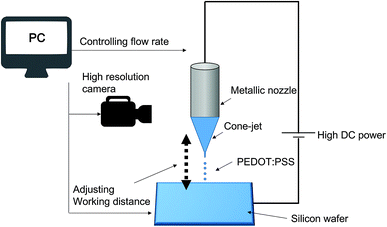
As shown in Fig. 1, a metallic nozzle holder attached to a glass syringe in an EHD printing setup (Enjet, Korea) was filled with either of the three PEDOT:PSS solutions described above. These solutions were ejected at flow rates from 0.1 to 1 μL min−1 using a motorized pump through a 220 μm diameter nozzle. The electric field applied between the nozzle and the aluminum substrate was generated using the installed power supply. An x, y-axis stage was used to control printing speed and working distance, which controlled line width. The whole process was interfaced with a computer and was monitored using a CCD camera.Characterization
The contact angles of the samples were measured using a contact angle meter system (OCA20, Dataphysics Instruments GmbH, Germany). The meniscuses formed under various jetting conditions were monitored using the CCD camera. PEDOT:PSS thin films were fabricated to measure sheet resistances, by spin-coating PEDOT:PSS solutions containing various amounts of Triton X-100 at 2000 rpm for 20 s. Deposited films were annealed at 120 °C for 30 min, and then sheet resistances were measured using the 4-point probe method. Line resistances of the printed PEDOT:PSS lines were measured using a Keithley 4200-SCS system.3. Results and discussion
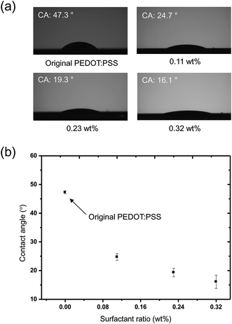
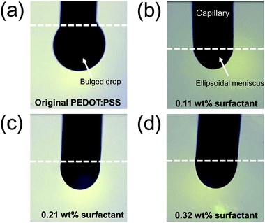
The contact angles (CAs) of PEDOT:PSS solutions containing various amounts of Triton X-100 are summarized in Fig. 2. As the amount of surfactant was increased from 0.11 to 0.32 wt%, contact angles decreased from 47.3 to 16.1° (Fig. 2a). Tendency to decrease in the CA according to the amount of surfactant was displayed in Fig. 2b. This is attributed to a decrease in surface tension as demonstrated by previous studies.28,29 The ability to control the surface tension of an ink is important for the EHD printing process. The successful EHD printing of an ink can be achieved when the electric force overcomes the surface tension and then an ellipsoidal meniscus for micro-dripping mode or conical meniscus for stable cone-jet mode are formed at the end of the capillary. Thus, it is necessary to adjust the surface tension of the PEDOT:PSS solution to the acceptable level for the patterning in EHD printing process.The effect of surface tension on EHD jetting mode was tested by examining PEDOT:PSS solutions possessing three different concentrations of Triton X-100: 0.11, 0.21 and 0.32 wt%. We carefully inspected the printing parameters (flow rate and applied voltage) for the formation of a micro-dripping mode when printing three PEDOT:PSS solutions. The working distance between the substrate to the nozzle and the flow rate were fixed at 500 μm and 0.5 μL min−1, respectively. During the micro-dripping mode (characterized by a stable ellipsoidal meniscus), drops detached from the end of the capillary as the electric field overcame the surface tension of an ink without the additional forces, such as gravity.30 Thus, this experiment allowed to understand the relationship between surface tension affected by the amount of Triton X-100 and the applied voltage. When 4 kV was applied to the nozzle, the original PEDOT:PSS solution created a bulging drop, which hung on the capillary as shown in Fig. 3a. Under this condition, the applied voltage could not induce a electric force to overcome the surface tension of PEDOT:PSS solution owing to too high surface tension of PEDOT:PSS. Instead, gravity dominated, and no jetting was observed. By contrast, an obvious ellipsoidal meniscus was observed for 1- (Fig. 3b), 2- (Fig. 3c), and 3-PEDOT:PSS (Fig. 3d) solutions due to decrease in the surface tension by the effect of the surfactant.
PEDOT:PSS solutions containing more surfactant tended to require lower voltages to generate the initial micro-droplets at a given flow rate (0.5 μL min−1) and working distance (500 μm) (Fig. 4). The difference between the applied voltages required for 1-PEDOT:PSS (1.01 kV) and 3-PEDOT:PSS (0.85 kV) was 0.16 kV. In general, the magnitude of the charges on a drop that can overcome its own surface tension follows the Rayleigh limiting charge,25,31 as described by:
| qmax = π(8ε0γdd3)1/2, | (1) |
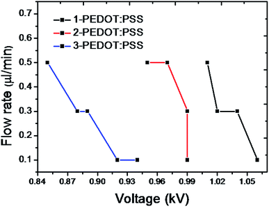 | ||
| Fig. 4 Relationship between applied voltage and flow rate to achieve micro-dripping for 1, 2, and 3-PEDOT:PSS. | ||
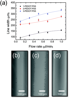
During the EHD printing process for pattering conductive lines, the cone-jet mode enables the fine patterning of printed lines because the diameter of the jet ejected from the apex of a liquid cone is much smaller than that of the nozzle, as observed in Fig. 5a.30 Printing parameters (working distance and the voltage applied between the nozzle and substrate) required to form a stable cone-jet mode as a function of surface tension are provided in Fig. 5b. All PEDOT:PSS solutions containing three different concentrations of Triton X-100 achieved a stable cone-jet mode at the low voltage of 0.5 kV, which is approximately one order of magnitude lower than achieved by previous research that used isopropanol to reduce the surface tension of PEDOT:PSS solution.27 Furthermore, 3-PEDOT:PSS, which had the lowest surface tension, allowed cone-jet mode at longest working distance at given voltages. It should be noted that if induced intensity of electric field, which is strengthened by increase in applied voltage and decrease in working distance, is too high in order to overcome a surface tension of a liquid, electrical breakdown hindering printing stability easily occurs. This problem is another reason why a lower surface tension is preferred. When a stable cone-jet was achieved, the line width of the printed film varied by controlling the flow rate between 0.1 and 1 μL min−1, as shown in Fig. 6a. As the flow rate increased, line width increased from 91 μm (Fig. 6b) to 158 μm for 1-PEDOT:PSS, from 209 μm (Fig. 6c) to 278 μm for 2-PEDOT:PSS, and from 233 μm (Fig. 6d) to 335 μm for 3-PEDOT:PSS. This indicates the volume of the PEDOT:PSS solution extruded from the capillary depends on the flow rate. Furthermore, increasing the surfactant concentration at constant flow rate increased the printed line width, presumably due to the improved wettability (see Fig. 2).
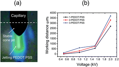 | ||
| Fig. 5 Image of line printing using PEDOT:PSS in stable cone-jet mode (a) and the required voltages and working distances required to this mode for 1, 2 and 3-PEDOT:PSS solutions (b). | ||
To determine the sheet resistances of three PEDOT:PSS films with the solutions having three different concentrations of Triton X-100, the four-point probe method was utilized.32 According to this method, a current is passed through two outer probes, and two inner probes measure voltage. Table 1 shows the enhancement in film conductivity achieved by adding Triton X-100. In fact, film conductivity increased from 0.03 S cm−1 for pristine PEDOT:PSS to 11.90 S cm−1 for 3-PEDOT:PSS. In general, PEDOT:PSS as an electrode has been extensively used in optoelectronic devices. However, it is usually used as a buffer layer between an electrode and an active layer due to its low conductivity (∼1 S cm−1), which is remarkably lower than the conductivity of ITO.33,34 Recently, several reports introduced about increasing the conductivity of PEDOT:PSS by the addition of solvents such as ethylene glycol (EG), dimethyl sulfoxide (DMSO), and sorbitol.35–38 Kim et al. reported that the addition of EG and thermal post-treatment could increase the conductivity of PEDOT:PSS to 1418 S cm−1.39 In addition, a variety of dopants, acids and processing techniques have been used to increase the conductivity of PEDOT:PSS.39–43 Vapor phase polymerization of EDOT also increased PEDOT film conductivity to as high as 1500 S cm−1,42 and treatment of PEDOT:PSS with formic acid induced a remarkable increase in conductivity of up to 2050 S cm−1.43 However, for printing under ambient conditions, vapor-phase polymerization and the use of hazardous materials are undesirable. In particular, the physicochemical properties of the used materials and solutions should fulfill the specific requirements of printing systems. For example, PEDOT:PSS ink with too high viscosity or surface tension is likely to cause nozzle clogging or hinder the formation of stable cone-jet during EHD printing (see Fig. S1 in the ESI†). Therefore, adding nonionic surfactant is probably the most effective means of increasing PEDOT:PSS conductivity and of decreasing the surface tension of PEDOT:PSS solution in the EHD printing process.
| Original PEDOT:PSS | 1-PEDOT:PSS | 2-PEDOT:PSS | 3-PEDOT:PSS | |
|---|---|---|---|---|
| Sheet resistance (Ω □−1) | 2.32 × 10⁶ | 1.72 × 10⁵ | 2.2 × 10³ | 2.1 × 10³ |
| Conductivity (S cm−1) | 0.03 | 0.14 | 11.36 | 11.90 |
In this work, Triton X-100 reduced the resistance of EHD-printed PEDOT:PSS film, although the value of conductivity (11.90 S cm−1) was not reached to that of reported one containing Triton X-100 (∼100 S cm−1 at 1 wt%),29,44 which is possibly because of different ink compositions, film dimensions, and experimental conditions. In fact, PEDOT:PSS film produced without any additives had a disconnected PEDOT-rich granular (average grain size 20–30 nm) PSS matrix structure.44–48 Excess hydrophilic PSS chains, which are required to disperse PEDOT:PSS in water, surround hydrophobic PEDOT regions and isolate them from water, and PEDOT (positive charged) and PSS (negative charged) interact by coulombic attraction.45,46 This coulombic attraction between inter-chains can screen coulombic repulsions of anions in the PSS chain, and leads to a coiled PEDOT:PSS conformation.45,46 Furthermore, these structural features may be regarded as the main cause of the low conductivity of pure PEDOT:PSS film.45,46 However, when nonionic surfactant is added to PEDOT:PSS, the surfactant molecules locate to the interface between PEDOT and PSS because the hydrophobic and hydrophilic portions of the nonionic surfactant interact the corresponding regions of PEDOT and PSS chains, respectively. This phase segregation behavior can reduce coulombic attraction between PEDOT and PSS, and enhance coulombic repulsion between same charges in the intra-chains, which gives rise to the structural change in PEDOT:PSS from a coil to a linear or an extended-coil conformation.44–48 Hence, we believe that the conformational changes of PEDOT:PSS chains induced by adding nonionic surfactant probably transform PEDOT:PSS film morphology from disconnected PEDOT-rich granular gain structure to interconnected PEDOT network, which is a main cause of the improved conductivity of PEDOT:PSS containing Triton X-100. This proposed mechanism is supported by several studies.44–48 Bao group demonstrated the introduction of the fluoropolymer surfactant Zonyl to PEDOT:PSS allowed phase segregation between PEDOT and PSS, and then caused PEDOT grains to elongate and to form an interconnected PEDOT network.47 As a result, the sheet resistance of PEDOT:PSS decreased from over 105 Ω sq−1 (without Zonyl) to 240 Ω sq−1, but it should be noted that DMSO was also added to PEDOT:PSS to increase the conductivity.47 Jeong group reported that phase segregation caused by the addition of nonionic surfactant to PEDOT:PSS led to the formation of PEDOT nanofibril network and enhanced conductivity.44 In addition, Ouyang group proposed a similar mechanism where both a co-solvent system46 and zwitterionic surfactant48 caused phase segregation of PEDOT and PSS that gave rise to the formation of interconnected PEDOT network. These results demonstrate nonionic surfactant can increase the conductivity of PEDOT:PSS markedly.
Fig. 7a plots the relationship between line resistance per unit length (mm) and number of printing. The lines of each sample were printed at the constant voltage of 1.8 kV and flow rate of 0.1 μL min−1 with variations of working distance to form the stable cone-jet mode. The line resistance, denoted (R/mm), is defined as
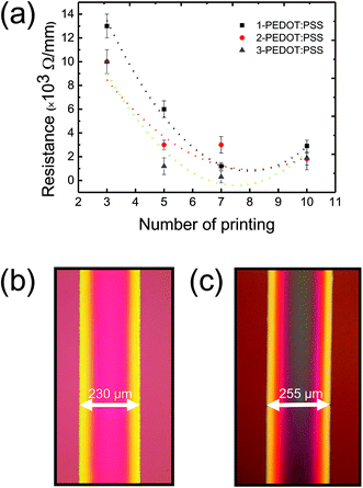 | ||
| Fig. 7 Line resistance of PEDOT:PSS films versus the number of printings (a). Images of EHD printed PEDOT:PSS lines obtained using third (b) and seventh (c) time printing of 3-PEDOT:PSS. | ||
4. Conclusion
In this study, we systematically investigated the effects of a surfactant on the surface tension of a PEDOT:PSS solution for use in an EHD printing process. By modulating the surface tension using a nonionic surfactant Triton X-100, we found that the EHD-jet printing method could be tuned to a specific jetting mode such as the micro-dripping or cone-jet mode at low powers. Furthermore, printed line resolution could be controlled by adjusting the flow rate. In addition, it was found that the conductivity of the PEDOT:PSS film was enhanced by a factor of 100 by adding Triton X-100, which makes the PEDOT:PSS polymer system suitable for electrode fabrication in functional devices.Acknowledgements
This work was supported by the Korean National Research Foundation (NRF) funded by the Korea government (Grant no. NRF-2014R1A1A1005896).References
- M. H. Yoon, A. Facchetti and T. J. Marks, Proc. Natl. Acad. Sci. U. S. A., 2005, 102, 4678 CrossRef CAS PubMed
.
- H. Shi, C. Liu, Q. Jiang and J. Xu, Adv. Electron. Mater., 2015, 1, 1500017 Search PubMed
.
- K. Sun, S. Zhang, P. Li, Y. Xia, X. Zhang, D. Du, F. H. Isikgor and J. Ouyang, J. Mater. Sci.: Mater. Electron., 2015, 26, 4438 CrossRef CAS
.
- A. M. Nardes, M. Kemerink, M. M. Kok, E. Vinken, K. Maturova and R. A. J. Janssen, Org. Electron., 2008, 9, 727 CrossRef CAS
.
- E. Armelin, A. Meneguzzi, C. A. Ferreira and C. Aleman, Surf. Coat. Technol., 2009, 203, 3763 CrossRef CAS
.
- H. Sirringhaus, T. Kawase, R. H. Friend, T. Shimoda, M. Inbasekaran, W. Wu and E. P. Woo, Science, 2000, 290, 2123 CrossRef CAS PubMed
.
- B. Charlot, G. Sassine, A. Garraud, B. Sorli, A. Garraud, B. Sorli and P. Combette, Microsyst. Technol., 2013, 19, 895 CrossRef CAS
.
- P. G. Taylor, J. K. Lee, A. A. Zakhidov, M. Chatzichristidi, H. H. Fong, J. A. deFranco, G. G. Malliaras and C. K. Ober, Adv. Mater., 2009, 21, 2314 CrossRef CAS
.
- S. Ouyang, Y. Xie, D. Wang, D. Zhu, X. Xu, T. Tan, J. deFranco and H. H. Fong, J. Polym. Sci., Part B: Polym. Phys., 2014, 52, 1221 CrossRef CAS
.
- S. Takamatsu, T. Takahata, K. Matsumoto and I. Shimoyama, J. Micromech. Microeng., 2011, 21, 075021 CrossRef
.
- D. S. Leem, P. H. Wöbkenberg, J. Huang, T. D. Anthopoulos, D. D. C. Bradley and J. C. deMello, Org. Electron., 2010, 11, 1307 CrossRef CAS
.
- U. Lang, P. Rust, B. Schoberle and J. Dual, Microelectron. Eng., 2009, 86, 330 CrossRef CAS
.
- A. Takakuwa, M. Ikawa, M. Fujita and K. Yase, Jpn. J. Appl. Phys., 2007, 46, 5960 CrossRef CAS
.
- A. L. Briseno, M. Roberts, M. M. Ling, H. Moon, E. J. Nemanick and Z. Bao, J. Am. Chem. Soc., 2006, 128, 3880 CrossRef CAS PubMed
.
- B. D. Chan, K. H. Hsieh and S. Y. Yang, Microelectron. Eng., 2009, 86, 586 CrossRef CAS
.
- A. F. Lasagni, J. L. Hendricks, C. M. Shaw, D. Yuan, D. C. Martin and S. Das, Appl. Surf. Sci., 2009, 255, 9186 CrossRef CAS
.
- F. J. Touwslager, N. P. Willard and D. M. Leeuw, Appl. Phys. Lett., 2002, 81, 4556 CrossRef CAS
.
- E. Menard, M. A. Meitl, Y. Sun, J. U. Park, D. J. L. Shir, Y. S. Nam, S. Jeon and J. A. Rogers, Chem. Rev., 2007, 107, 1117 CrossRef CAS PubMed
.
- S. H. Eom, H. Park, S. H. Mujawar, S. C. Yoon, S. S. Kim, S. I. Na, S. J. Kang, D. Khim, D. Y. Kim and S. H. Lee, Org. Electron., 2010, 11, 1516 CrossRef CAS
.
- X. Yuan, Z. Ba and Z. Xiong, J. Micromech. Microeng., 2015, 25, 075028 CrossRef
.
- A. A. Argun and J. R. Reynolds, J. Mater. Chem., 2005, 15, 1793 RSC
.
- N. Duraisamy, S. J. Hong and K. H. Choi, Chem. Eng. J., 2013, 225, 887 CrossRef CAS
.
- S. Lee, D. Byun, D. Jung, J. Choi, Y. Kim, J. H. Yang, S. U. Son, S. B. Q. Tran and H. S. Ko, Sens. Actuators, A, 2008, 141, 506 CrossRef CAS
.
- J. U. Park, M. Hardy, S. J. Kang, K. Barton, K. Adair, D. K. Mukhopadhyay, C. Y. Lee, M. S. Strano, A. G. Alleyne, J. G. Georgiadis, P. M. Ferreira and J. A. Rogers, Nat. Mater., 2007, 6, 782 CrossRef CAS PubMed
.
- S. E. Park, J. Y. Hwang, K. Kim, B. Jung, W. Kim and J. Hwang, Sol. Energy Mater. Sol. Cells, 2011, 95, 352 CrossRef CAS
.
- J. C. Ijsebaert, K. B. Geerse, J. C. M. Marijnissen, J. W. J. Lammers and P. Zanen, J. Appl. Physiol., 2001, 91, 2735 CAS
.
- N. Duraisamy, N. M. Muhammad, A. Ali, J. Jo and K. H. Choi, Mater. Lett., 2012, 83, 80 CrossRef CAS
.
- F. J. Lim, K. Ananthanarayanan, J. Luther and G. W. Ho, J. Mater. Chem., 2012, 22, 25057 RSC
.
- J. B. Lee, K. Rana, B. H. Seo, J. Y. Oh, U. Jeong and J. H. Ahn, Carbon, 2015, 85, 261 CrossRef CAS
.
- A. Jaworek and A. Krupa, J. Aerosol Sci., 1999, 30, 873 CrossRef CAS
.
- N. V. Krasnov and S. I. Shevchenko, Rev. Sci. Instrum., 1995, 66, 3623 CrossRef CAS
.
- W. Zhang, B. Zhao, Z. He, X. Zhao, H. Wang, S. Yang, H. Wu and Y. Cao, Energy Environ. Sci., 2013, 6, 1956 CAS
.
- Y. Cao, G. Yu, C. Zhang, R. Menon and A. J. Heeger, Synth. Met., 1997, 87, 171 CrossRef CAS
.
- L. B. Groenendaal, F. Jonas, D. Freitag, H. Peilartzik and J. R. Reynolds, Adv. Mater., 2000, 12, 481 CrossRef CAS
.
- F. Zhang, M. Johansson, M. R. Andersson, J. C. Hummelen and O. Inganäs, Adv. Mater., 2002, 14, 662 CrossRef CAS
.
- X. Crispin, F. L. E. Jakobsson, A. Crispin, P. C. M. Grim, P. Andersson, A. Volodin, C. V. Haesendonck, M. V. Auweraer, W. R. Salaneck and M. Berggren, Chem. Mater., 2006, 18, 4354 CrossRef CAS
.
- J. Huang, P. F. Miller, J. S. Wilson, A. J. Mello, J. C. Mello and D. D. C. Bradley, Adv. Funct. Mater., 2005, 15, 290 CrossRef CAS
.
- J. Ouyang, C. W. Chu, F. C. Chen, Q. Xu and Y. Yang, Adv. Funct. Mater., 2005, 15, 203 CrossRef CAS
.
- Y. H. Kim, C. Sachse, M. L. Machala, C. May, L. M. Meskamp and K. Leo, Adv. Funct. Mater., 2011, 21, 1076 CrossRef CAS
.
- Y. Xia, K. Sun and J. Ouyang, Adv. Mater., 2012, 24, 2436 CrossRef CAS PubMed
.
- B. W. Jensen and K. West, Macromolecules, 2004, 37, 4538 CrossRef
.
- M. Fabretto, C. J. Moncunill, J. P. Autere, A. Michelmore, R. D. Short and P. Murphy, Polymer, 2011, 52, 1725 CrossRef CAS
.
- D. A. Mengistie, M. A. Ibrahem, P. C. Wang and C. W. Chu, ACS Appl. Mater. Interfaces, 2014, 6, 2292 CAS
.
- J. Y. Oh, M. Shin, J. B. Lee, J. H. Ahn, H. K. Baik and U. Jeong, ACS Appl. Mater. Interfaces, 2014, 6, 6954 CAS
.
- B. Fan, X. Mei and J. Ouyang, Macromolecules, 2008, 41, 5971 CrossRef CAS
.
- Y. Xia and J. Ouyang, J. Mater. Chem., 2011, 21, 4927 RSC
.
- M. Vosgueritchian, D. J. Lipomi and Z. Bao, Adv. Funct. Mater., 2012, 22, 421 CrossRef CAS
.
- Y. Xia, H. Zhang and J. Ouyang, J. Mater. Chem., 2010, 20, 9740 RSC
.
Footnotes |
| † Electronic supplementary information (ESI) available. See DOI: 10.1039/c5ra19462h |
| ‡ Equally contributed as first authors. |
| This journal is © The Royal Society of Chemistry 2016 |

