
A high-pressure synthesis of hydrothermally stable periodic mesoporous crystalline aluminosilica materials†
Manik Mandala,
Amanpreet S. Manchandab,
Cong Liua,
Yingwei Feic and
Kai Landskron*a
aDepartment of Chemistry, Lehigh University, Bethlehem, PA, USA. E-mail: kal205@lehigh.edu; Fax: +1 610 758 6536; Tel: +1 610 758 5788
bDepartment of Chemistry, College of Staten Island, City University of New York, Staten Island, NY, USA
cGeophysical Laboratory, Carnegie Institution of Washington, Washington, DC, USA
First published on 13th January 2016
Abstract
We report a synthetic route to mesoporous crystalline aluminosilica materials using high pressure and temperature. In the first step a large-pore periodic mesoporous aluminosilica SBA-15 material was filled with carbon at ambient pressure. We observed that crystallization of the pore walls of periodic mesoporous aluminosilica/carbon composites occurred at 2 GPa and a temperature of 650 °C without significant distortion of the mesostructure. Combustive removal of carbon from the crystallized composite in air led to the formation of periodic mesoporous crystalline aluminosilica materials. These materials are steam stable and are resistant to shrinkage under the harsh conditions of hydrothermal treatment at 800 °C.
Introduction
Periodic mesoporous silica was first discovered in 1992.1,2 The initial motivation for the synthesis of such materials was to replace microporous zeolite materials for application as a catalyst for petroleum cracking. However, soon it was realized that mesoporous silica materials have inferior hydrothermal stability because of the amorphous nature of their pore walls. Aluminum has been incorporated into the mesoporous silica networks, which led to the introduction of acidity into the material. The introduction of aluminium into mesoporous silica can be done by two ways: direct co-assembly or post-synthetic modification.3 The first method is very efficient for achieving high aluminum loadings in the silica networks. However, the mesostructure of the material is often lost by using this method. Post-synthetic modification keeps the mesostructural order intact. However, the latter method limits the amount of incorporated aluminium. Aluminosilicas obtained by any of these routes have amorphous pore walls. The non-crystalline channel walls of mesoporous aluminosilicas makes them less hydrothermally stable and limits their acidity compared to microporous zeolites.4Therefore efforts were made to obtain hierarchical micro–mesoporous aluminosilica material with crystalline zeolitic channel walls. Mesoporous silicas and carbons were used as hard template and impregnated with a zeolite precursor solution.5,6 Then the composite materials were crystallized under hydrothermal conditions. Mokaya et al. used mesoporous carbon as template and infiltrated it with a precursor gel of ZSM-5 followed by crystallization using a steam-assisted crystallization (SAC) method.6,7 Choi et al. synthesized micro/mesoporous aluminosilica with pore walls having the ZSM-5 structure using a similar method.5 In this method mesoporous silica was first impregnated with aluminum ions to form mesoporous aluminosilica. Then the pores of the aluminosilica were filled with a phenol/formaldehyde mixture by the wet incipient technique followed by carbonization to produce aluminosilica/carbon nanocomposites. The composite material was then impregnated with tetrapropylammonium hydroxide (TPAOH) and crystallized through the SAC process. The resulting material crystallized in the ZSM-5 structure. Hu et al. used a similar technique to produce mesoporous crystalline aluminosilica using Al-SBA-15/CMK-5 nanocomposites.8 Ogura et al. also used a mesoporous silica/carbon composite and crystallized it under hydrothermal conditions.9 The removal of carbon was carried out by calcination under air to produce mesoporous aluminosilica with crystalline zeolitic channel walls. All these methods are based on hydrothermal synthesis of zeolites and require several days to weeks for crystallization. Typically, alkylammonium surfactants are used for crystallization of the aluminosilica during hydrothermal treatment.
Recently ordered mesoporous zeolites have also been made by soft-templating techniques.10–14 Notably, Ryoo et al. synthesized mesoporous zeolites using custom-made alkylammonium surfactants with long alkyl chains under conditions similar to the synthesis of microporous zeolites.10 These surfactants contain zeolite structure-directing groups and long alkyl chains. The zeolite structure-directing groups are responsible for the formation of zeolitic crystalline walls while the long alkyl chains are responsible for the generation of mesopores. Recently our group has found a high pressure route as a method for the synthesis of periodic mesoporous quartz, coesite, and stishovite.15–18 The crystallization of the silica is achieved through applying temperatures between 300 and 750 °C at high pressure (2–14 GPa). In this approach, a mesoporous silica/carbon nanocomposite is used as starting material. It is believed that the carbon phase acts as pressure transmitting medium which stabilizes the mesostructure at high pressure during the crystallization process. After the crystallization is complete, the material can be decompressed. After the decompression is complete, the carbon can be removed by oxidation in air generating the mesopores. While silica does not crystallize even at 1000 °C at atmospheric pressure, high pressure crystallizes the silica at relatively mild temperatures.16,19–22 The materials have shown to be hydrothermally stable at temperatures of 800 °C in pure steam.15
So far, the high-pressure synthesis has been successfully used to obtain crystalline mesoporous SiO2 and mesoporous diamond materials only.23,24 However, these materials are not expected to be catalytically active due to the absence of a heteroatom such as aluminium. Here we report on the synthesis of mesoporous crystalline aluminosilica materials under HPHT. Hydrothermal stability studies showed that the material is stable under the conditions similar to those required for petroleum cracking.
Experimental section
Synthesis of mesoporous aluminosilica and aluminosilica/carbon nanocomposites
The mesoporous aluminosilica material with a two-dimensional hexagonal structure was synthesized following the in situ pH adjusting method similar to literature procedures.25,26 In a typical synthesis, 0.8 g of Pluronic P123 (EO20PO70EO20) block-copolymer was dissolved in 25 ml of 2 M HCl solution followed by magnetic stirring in a closed polypropylene (PP) bottle until the surfactant dissolved completely at a temperature of 40 °C. 1.7 g of tetraethoxysilane, TEOS (Gelest) was added to this solution. After stirring for 4 h, 1.36 g of Al2(SO4)3·xH2O (x ∼ 14–18, Alfa Aesar) was added to the mixture and stirring was continued for 1 day at the initial synthesis temperature. Then, the whole solution was hydrothermally treated for 2 days at 100 °C. Then, the pH of the reaction mixture was adjusted to ∼7.5 by adding conc. NH4OH solution drop-wise and then again treated hydrothermally for 2 days at 100 °C. The resulting as-synthesized material was then centrifuged, washed with deionized water, and dried. Finally, the surfactant was removed by calcination under air at 550 °C (heating ramp 2 °C min−1) for 5 h to obtain mesoporous aluminosilica material, Al-SBA-15.The calcined Al-SBA-15 material was used for the synthesis of aluminosilica/carbon nanocomposites through the incipient wetness technique. AR-Mesophase pitch (Mitsubishi Gas and Chemical) was used as carbon precursor. Briefly, grounded mesophase pitch was sonicated with calcined Al-SBA-15 material suspended in ethanol. The solvent was evaporated by stirring the whole mixture overnight at ∼40 °C. The solid mixture was then heated in a tube furnace under nitrogen atmosphere. To infiltrate the pitch, the temperature was raised from room temperature to 500 °C at a rate of 5 °C min−1 and kept for 8 h. Then, the temperature was further raised to 850 °C at the rate of 5 °C min−1 for 4 h for carbonization. The so-obtained Al-SBA-15/C nanocomposite was used for high-pressure experiments.
High-pressure experiment
The experiments at a pressure up to 2 GPa were carried out using an end-loaded piston cylinder apparatus. The starting material was encapsulated in a platinum capsule and wielded shut. Cylindrical graphite was used as heater. The sample was compressed first at the desired pressure at room temperature and then heated to 750 °C (or other temperatures) at a rate of 100 °C min−1. The sample was kept under these conditions for 6 h and then quenched to ambient conditions.The experiments at a pressure of 4 GPa were carried out using a multi-anvil assembly and a 1500 ton hydraulic press. The details of the multi-anvil experiments can be found in the ESI.† The sample was compressed to the desired pressure at a rate of 2 GPa h−1 at room temperature, then heated to the final temperature at a rate of 100 °C min−1 and kept at the target pressure–temperature for 3 h. After that, the pressure was released at a rate of 2 GPa h−1. After normal pressure was reached, the sample was extracted from the capsule for characterization.
Hydrothermal stability study
The hydrothermal stability studies for mesoporous crystalline and amorphous aluminosilica material were carried out in a tube furnace. Pure steam was passed through the tube for 2 h at 800 °C.Measurements
Wide-angle X-ray scattering (WAXS) data were acquired on a Rigaku MiniFlexII instrument using Cu Kα as radiation source. The small-angle X-ray scattering (SAXS) patterns were recorded using a Bruker Nanostar Instrument. Samples were placed in the hole of an aluminium sample holder and secured on both sides using tape. Nitrogen adsorption measurements at −196 °C were carried out using a Quantachrome Autosorb-1MP instrument. The samples were outgassed at 140 °C for overnight in high vacuum before analysis. The BJH method was used to calculate the pore size distributions using the adsorption branch of the isotherm. The surface area was determined using the multipoint BET method in the relative pressure range between 0.04 and 0.2. Transmission electron microscopy (TEM) images were recorded on a JEOL 2000FX instrument operated at an accelerating voltage of 200 kV. Energy dispersive X-ray analysis (EDAX) was carried out using Oxford ISIS EDS with a light element detector connected with the TEM. HR-TEM images were acquired using JEOL JEM-ARM200CF operated at an accelerating voltage of 60 kV. The samples were first sonicated in ethanol, and then drop-casted on a carbon-coated copper grid. The solvent was evaporated in air before analysis was carried out. SEM was carried out using a Hitachi S4200 instrument at an operating voltage of 5 kV.Results and discussion
Synthesis of mesoporous aluminosilica and aluminosilica/C nanocomposites
It was observed that the pH adjustment route was the most efficient method to incorporate aluminium into the mesoporous silica compared to the direct co-assembly or post-grafting route to produce mesoporous aluminosilica material in acidic media.3 Nitrogen adsorption, and TEM were used to characterize the mesoporosity of the synthesized material (Fig. S1 and S2†). The nitrogen isotherm shows a capillary condensation step at ∼0.72 indicating that the material is mesoporous. The material has a BET specific surface area of ∼336 m2 g−1, a pore volume of ∼1 cm3 g−1 and an NLDFT pore size of ∼8.2 nm with very narrow distribution (Fig. S1†). Additionally, SEM for this material shows rod-shaped structures, which is typical for an SBA-15 type material (Fig. S2†). Before the high-pressure experiment, the presence of aluminum was confirmed by EDS analysis, which showed that the channel walls were composed of only Al, Si and O atoms (Fig. S2†). The calcined Al-SBA-15 material was infiltrated with mesophase pitch (MP) and carbonized under nitrogen atmosphere at 850 °C. The complete filling of mesopores was confirmed by nitrogen adsorption, as there was insignificant adsorption of nitrogen gas molecules by the Al-SBA-15/C material (Fig. S1†). Additionally, thermogravimetric analysis of Al-SBA-15/C material in air showed major weight loss (∼38%) at a temperature of ∼550 °C, which is due to elimination of carbon (Fig. S3†).Synthesis of mesoporous crystalline aluminosilica materials
The synthesized Al-SBA-15/C nanocomposite material was first treated at a pressure of 2 GPa and a temperature of 350 °C for 6 h. After the high-pressure experiment, the material was calcined at 700 °C under air for 4 h to remove carbon. The calcined material was color-less indicating the removal of carbon. This material was then analyzed by X-ray diffraction, which showed that the material was amorphous in nature as seen from the featureless pattern in the XRD (Fig. 1). When the temperature was increased to 550 °C at 2 GPa, it appeared that the onset of crystallization already started as reflections were clearly observed at 2θ ∼20.6, and 26.5 degrees in the XRD pattern, which could be indexed to quartz. No reflections other than those for quartz were observed at this temperature. Increasing the temperature to 650 °C at 2 GPa, also afforded a crystalline material. The decreased linewidth of the reflections indicated increased crystallinity. No other phases were seen in the XRD indicating that the Al has been incorporated into the quartz structure as a dopant. Further increasing temperature to 750 °C, also yielded a crystalline material (indexed to quartz structure) with some additional peaks as seen from XRD. These additional peaks could be indexed to sillimanite which is a crystalline aluminosilica with the composition Al2SiO5.27,28 The formation of sillimanite may be because the Al doped quartz is less stable at higher temperature leading to the formation of undoped quartz and sillimanite. When the pressure was lowered to 1 GPa and a temperature of 750 °C was used, no crystallization of the aluminosilica phase took place as seen from XRD (Fig. S4†). This indicates that the onset pressure for crystallization of this system at 750 °C is between 1 and 2 GPa.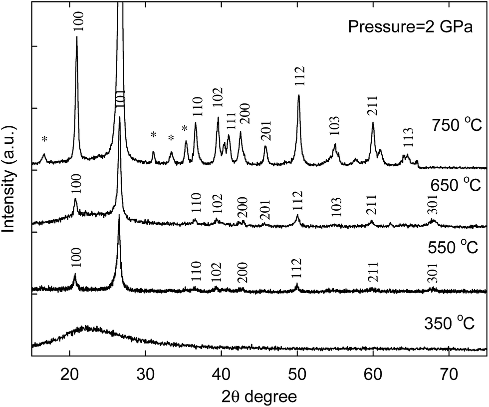 | ||
| Fig. 1 XRD patterns for the calcined alumina silica/carbon composites treated at 2 GPa and different temperatures for 6 h. The sample was calcined to remove carbon. Asterisk (*) could be indexed to sillimanite. | ||
The reflections of the SAXS patterns of the material obtained at 350 and 550 °C, could be clearly indexed to (100), (110), (200), and/or (210) indicating the presence of a 2D hexagonal mesostructure ordering (Fig. 2). When the temperature was raised to 650 °C, the material still showed the peaks for this structure. However, it can be seen that the intensity of the (100) peaks gradually broadens with increasing temperature, indicating that the mesostructural order decreases with increase in temperature (Fig. 2). Also the (100) peak position slightly shifts toward a lower 2θ value. This is somewhat surprising because one would rather expect an increase due to densification of the pore walls. For the material obtained from the experiment done at 750 °C, no peaks were observed indicating the loss of mesostructural ordering. For the material obtained at a pressure of 1 GPa and a temperature of 750 °C, the SAXS pattern shows a clear (100) peak indicating that mesostructural ordering is preserved (Fig. S5†). The results indicate that the crystallization induces gradual distortion of the mesostructure and the crystallization under maintenance of the mesostructure is only possible in a relatively small temperature and time window.
 | ||
| Fig. 2 SAXS patterns for the calcined alumina silica/carbon composites treated at 2 GPa and different temperatures for 6 h. The sample was calcined to remove carbon. | ||
Additionally, nitrogen adsorption was used to understand the mesoporosity of the synthesized materials (Fig. 3). Materials obtained at temperatures of 350, 550, and 650 °C showed a steep capillary condensation step at a relative pressure of ∼0.67–0.76 indicating that the materials are mesoporous. The materials obtained at 2 GPa and temperatures of 350, 550, 650, and 750 °C had surface area of 250, 322, 82, and 32 m2 g−1 respectively. However, there was no clear capillary condensation step for the material obtained at 750 °C indicating that the mesostructural ordering was lost due to the high temperature. The results corroborate the SAXS data (Fig. 2). On the other hand, for the material obtained at a pressure of 1 GPa and temperature of 750 °C, a capillary condensation step at p/p0 ∼ 0.70 was clearly observed indicating that the mesostructural ordering is intact (Fig. S6†).
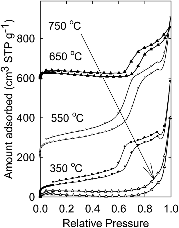 | ||
| Fig. 3 Nitrogen adsorption isotherms and pore size distributions of calcined aluminosilica synthesized at 2 GPa and different temperatures for 6 h. Isotherms for materials synthesized at 550 and 650 °C were offset vertically by 200 and 600 cm3 g−1 for clarity. | ||
To get further insight into the mesostructural ordering as well as the morphology, electron microscopy were carried out. The channel like pores were clearly visible from TEM images for the material obtained at a pressure of 2 GPa and temperatures of 350, 550, and 650 °C (Fig. 4). The HR-TEM and corresponding FFT pattern showed the crystalline nature of the material obtained at 650 °C (Fig. 4D). However, for material obtained at 750 °C, the pores seem to be largely lost (Fig. S7†). The selected area electron diffraction (SAED) patterns showed presence of spots for materials obtained at 550, 650 and 750 °C indicating that the materials are crystalline except for the material obtained at 350 °C, which was mesoporous and amorphous as seen from XRD (Fig. 1 and S8†). These results are in accordance with XRD data (shown above, Fig. 1). SEM images for these materials showed features of small rod-shaped structures which are typically observed for SBA-15 materials (Fig. S9†).
 | ||
| Fig. 4 TEM images for calcined aluminosilica treated at 2 GPa and (A) 350, (B) 550, and (C) 650 °C for 6 h (inset corresponding SAED). (D) Representative HR-TEM for 2 GPa and 650 °C (inset shows corresponding FFT pattern). Scale bar on the right is 10 nm. | ||
Hydrothermal stability studies
To investigate the hydrothermal stability, the crystalline mesoporous aluminosilica material was treated in pure steam streamed at 800 °C for 2 h in a tube furnace. The aluminosilica material obtained at a pressure of 2 GPa and a temperature of 650 °C was used for this study. Under such conditions, the pore walls were already crystallized and mesostructural ordering was retained as observed from XRD and SAXS pattern (Fig. 1 and 2). The XRD for hydrothermally treated material showed reflections which are of comparable intensity indicating that the crystallized pore walls were largely retained (Fig. 5A). SAXS pattern also showed peaks having similar intensity as well as (100) peak position at same 2θ position indicating zero shrinkage of the mesostructures (Fig. 5B). The hydrothermal stability of crystalline aluminosilica was compared with that of amorphous aluminosilica before high-pressure treatment under similar conditions. From the SAXS pattern, it is clear that the amorphous aluminosilica shrinks by 4.1% under hydrothermal conditions (Fig. S10†). This result is in accordance with previous study, where it was shown that mesoporous aluminosilica with amorphous pore walls are hydrothermally more stable compared to their silica counterparts, however shrink under hydrothermal treatment in pure steam.29 The absence of shrinkage of the mesoporous crystalline aluminosilica material here is most likely related to the crystallinity of the pore walls. Additionally TEM confirmed the mesoporous structure of the material (Fig. 6). SAED showed diffraction spots indicating the material is crystalline. | ||
| Fig. 5 A) XRD, and (B) SAXS patterns for the crystalline mesoporous aluminosilica before and after hydrothermal treatment at 800 °C in pure steam for 2 h. For comparison, XRD and SAXS patterns for corresponding material before hydrothermal treatment were added. HT = Hydrothermal Treatment. | ||
 | ||
| Fig. 6 (A) TEM (inset SAED), and (B) HR-TEM for the crystalline mesoporous aluminosilica material after hydrothermal treatment at 800 °C under pure steam for 2 h (scale bar on the right is 10 nm). Inset in (B) shows corresponding FFT pattern. | ||
Pressure effect on crystallization
To understand the effect of pressure, the pressure was increased to 4 GPa and a similar temperature treatment for 3 h was performed. It was observed that at a pressure of 4 GPa and a temperature of 350 °C, the product material remained amorphous (Fig. 7). When temperature was increased to 550 °C, a smaller peak at 2θ ∼ 26.5 degree was visible, which could be indexed to (101) peak of quartz. Further increasing the temperature to 750 °C yielded in a crystalline silica material. All the reflections on XRD could be indexed to quartz. The smaller degree of crystallinity of the material produced at 550 °C/4 GPa compared to that made at 550 °C/2 GPa is surprising because higher pressure is expected to facilitate crystallization. The difference may be explained by the fact that the pressure in the multi-anvil assembly is more isostatic compared to the piston-cylinder assembly, respectively. | ||
| Fig. 7 XRD patterns for the calcined alumina silica/carbon composites treated at 4 GPa and different temperatures for 3 h. The sample was calcined to remove carbon. | ||
The SAXS pattern for the material obtained at 350 and 550 °C, the peaks could be indexed to (100), (110), (200), and/or (210) indicating the 2D hexagonal mesostructural ordering (Fig. 8). However, a broad shoulder appeared for the material obtained at 750 °C indicating the deterioration of mesostructural ordering.
 | ||
| Fig. 8 SAXS patterns for the alumina silica/carbon composites treated at 4 GPa and different temperatures for 3 h. The sample was calcined to remove carbon. | ||
Additionally TEM confirmed the mesoporous structure of the material (Fig. 9). SAED patterns did not show any diffraction spots for materials obtained at 350 and 550 °C, while for materials obtained at 750 °C, clear diffraction spots were visible. These results are in accordance with XRD data.
 | ||
| Fig. 9 TEM images and corresponding SAED for calcined aluminosilica treated at 4 GPa and (A) 350, (B) 550, and (C) 750 °C for 3 h. | ||
Conclusions
We report on the synthesis of mesoporous crystalline aluminosilica materials under high pressure and high temperature. It was observed that at a pressure of 2 GPa and temperature of 350 °C, the pore walls composed of aluminosilica remained largely amorphous. Increasing the temperature to 550 °C, resulted in the crystallization of the pore walls. At a temperature of 750 °C, the mesostructural order started to disintegrate at 2 GPa. The crystalline aluminosilica material was found to be steam stable at 800 °C for at least 2 h with no pore shrinkage, while aluminosilica with amorphous pore walls showed shrinkage of the pores. At 4 GPa, it was observed that the crystallization temperature is increased by ca. 100 °C. Because of the presence of aluminium in the silica network, the resultant aluminosilica materials could be useful as catalysts for petroleum cracking. As the pressure required for such crystallization is in the range of 2 GPa, the synthesis could be potentially scaled-up. We believe our approach could be extended to synthesize other heteroatom substituted mesoporous silica materials with crystalline channel walls.Acknowledgements
This work was supported by EFree, an energy frontier Research Center funded by the U.S. Department of Energy Office of Science, Office of Basic Energy Sciences under Award #DE-SG0001057. The authors also thank Prof. M. Kruk for access to SAXS system which was supported by the National Science Foundation through award CHE-0723028. We also thank Lehigh University, and the Carnegie Institution of Washington for additional financial support of the project. Dr Valerie Hillgren, Dr Vincenzo Stagno, and Dr Oleksandr Kurakevych (Alex) are gratefully acknowledged for technical assistance.Notes and references
- C. T. Kresge, M. E. Leonowicz, W. J. Roth, J. C. Vartuli and J. S. Beck, Nature, 1992, 359, 710–712 CrossRef CAS.
- J. S. Beck, J. C. Vartuli, W. J. Roth, M. E. Leonowicz, C. T. Kresge, K. D. Schmitt, C. T. W. Chu, D. H. Olson, E. W. Sheppard, S. B. McCullen, J. B. Higgins and J. L. Schlenker, J. Am. Chem. Soc., 1992, 114, 10834–10843 CrossRef CAS.
- F. Hoffmann, M. Cornelius, J. Morell and M. Fröba, Angew. Chem., Int. Ed., 2006, 45, 3216–3251 CrossRef CAS.
- Y. Liu and T. J. Pinnavaia, J. Mater. Chem., 2002, 12, 3179–3190 RSC.
- S. I. Cho, S. D. Choi, J.-H. Kim and G.-J. Kim, Adv. Funct. Mater., 2004, 14, 49–54 CrossRef CAS.
- Z. Yang, Y. Xia and R. Mokaya, Adv. Mater., 2004, 16, 727–732 CrossRef CAS.
- W. Xu, J. Dong, J. Li, J. Li and F. Wu, J. Chem. Soc., Chem. Commun., 1990, 755–756 RSC.
- Y. Fang and H. Hu, J. Am. Chem. Soc., 2006, 128, 10636–10637 CrossRef CAS.
- M. Ogura, K. Inoue and T. Yamaguchi, Catal. Today, 2011, 168, 118–123 CrossRef CAS.
- M. Choi, H. S. Cho, R. Srivastava, C. Venkatesan, D.-H. Choi and R. Ryoo, Nat. Mater., 2006, 5, 718–723 CrossRef CAS.
- W. Fan, M. A. Snyder, S. Kumar, P.-S. Lee, W. C. Yoo, A. V. McCormick, R. L. Penn, A. Stein and M. Tsapatsis, Nat. Mater., 2008, 7, 984–991 CrossRef CAS.
- M. Choi, K. Na, J. Kim, Y. Sakamoto, O. Terasaki and R. Ryoo, Nature, 2009, 461, 246–250 CrossRef CAS.
- K. Na, C. Jo, J. Kim, K. Cho, J. Jung, Y. Seo, R. J. Messinger, B. F. Chmelka and R. Ryoo, Science, 2011, 333, 328–332 CrossRef CAS.
- J. Jiang, J. L. Jorda, J. Yu, L. A. Baumes, E. Mugnaioli, M. J. Diaz-Cabanas, U. Kolb and A. Corma, Science, 2011, 33, 1131–1134 CrossRef.
- P. Mohanty, B. Kokoszka, C. Liu, M. Weinberger, M. Mandal, V. Stagno, Y. Fei and K. Landskron, Microporous Mesoporous Mater., 2012, 152, 214–218 CrossRef CAS.
- P. Mohanty, Y. Fei and K. Landskron, J. Am. Chem. Soc., 2009, 131, 9638–9639 CrossRef CAS.
- V. Stagno, M. Mandal, W. Yang, C. Ji, Y. Fei, H.-K. Mao and K. Landskron, Microporous Mesoporous Mater., 2014, 187, 145–149 CrossRef CAS.
- V. Stagno, M. Mandal, K. Landskron and Y. Fei, Phys. Chem. Miner., 2015, 42, 509–515 CrossRef CAS.
- P. Mohanty, D. Li, T. Liu, Y. Fei and K. Landskron, J. Am. Chem. Soc., 2009, 131, 2764–2765 CrossRef CAS.
- P. Mohanty, V. Ortalan, N. D. Browning, I. Arslan, Y. Fei and K. Landskron, Angew. Chem., Int. Ed., 2010, 49, 4301–4305 CrossRef CAS.
- M. Mandal and K. Landskron, Acc. Chem. Res., 2013, 46, 2536–2544 CrossRef CAS.
- M. Mandal, V. Stagno, Y. Fei and K. Landskron, Cryst. Growth Des., 2013, 13, 15–18 CAS.
- L. Zhang, P. Mohanty, N. Coombs, Y. Fei, H.-K. Mao and K. Landskron, Proc. Natl. Acad. Sci. U. S. A., 2010, 107, 13593–13596 CrossRef CAS.
- M. Mandal, F. Haso, T. Liu, Y. Fei and K. Landskron, Chem. Commun., 2014, 50, 11307–11310 RSC.
- S. Wu, Y. Han, Y.-C. Zou, J.-W. Song, L. Zhao, Y. Di, S.-Z. Liu and F.-S. Xiao, Chem. Mater., 2004, 16, 486–492 CrossRef CAS.
- G. L. Athens, D. Kim, J. D. Epping, S. Cadars, Y. Ein-Eli and B. F. Chmelka, J. Am. Chem. Soc., 2011, 133, 16023–16036 CrossRef CAS.
- R. C. Newton and C. E. Manning, Chem. Geol., 2008, 249, 250–261 CrossRef CAS.
- D. L. Lakshtanov, S. V. Sinogeikin, K. D. Litasov, V. B. Prakapenka, H. Hellwig, J. Wang, C. Sanches-Valle, J.-P. Perrillat, B. Chen, M. Somayazulu, J. Li, E. Ohtani and J. D. Bass, Proc. Natl. Acad. Sci. U. S. A., 2007, 104, 13588–13590 CrossRef CAS.
- Q. Li, Z. Wu, B. Tu, S. S. Park, C.-S. Ha and D. Zhao, Microporous Mesoporous Mater., 2010, 135, 95–104 CrossRef CAS.
Footnote |
| † Electronic supplementary information (ESI) available: SAXS patterns, XRD, TEM, and SEM images. See DOI: 10.1039/c5ra15515k |
| This journal is © The Royal Society of Chemistry 2016 |