Electrospun carbon nanofiber@CoS2 core/sheath hybrid as an efficient all-pH hydrogen evolution electrocatalyst†
Huahao
Gu
a,
Yunpeng
Huang
a,
Lizeng
Zuo
a,
Wei
Fan
*b and
Tianxi
Liu
*ab
aState Key Laboratory of Molecular Engineering of Polymers, Department of Macromolecular Science, Fudan University, 220 Handan Road, Shanghai 200433, P. R. China. E-mail: txliu@fudan.edu.cn; txliu@dhu.edu.cn; Fax: +86-21-65640293; Tel: +86-21-55664197
bState Key Laboratory for Modification of Chemical Fibers and Polymer Materials, College of Materials Science and Engineering, Donghua University, 2999 North Renmin Road, Shanghai 201620, P. R. China. E-mail: weifan@dhu.edu.cn
First published on 16th August 2016
Abstract
Developing all-pH and efficient non-noble-metal electrocatalysts for the hydrogen evolution reaction (HER) remains a great challenge in science nowadays. In this work, carbon nanofiber (CNF)@CoS2 hybrids with a hierarchical core/sheath structure have been successfully fabricated via a combination of electrospinning and hydrothermal methods for use as HER electrocatalysts under all-pH media. The CoS2 nanoparticles are uniformly attached onto the three-dimensional (3D) CNF framework, and have different morphologies on adjusting the concentration of the Co and S precursors. This shows that the morphology of the electrocatalytically active CoS2 has a great impact on the HER performance, which can be attributed to the difference in the exposure of the effective catalytic sites. Moreover, the CNF@CoS2 hybrids distinctly exhibit superior HER activities compared to that of pure CoS2 agglomerates, which highlights the importance of the 3D carrier with a nanostructure to increase the number of exposed electrocatalytic sites. When applied as electrocatalysts operating at all-pH values, the CNF@CoS2 hybrids exhibit remarkable HER properties, with a low onset potential of −40 mV, a small Tafel slope of 66.8 mV per decade and a large current density (10.0 mA cm−2 at η = 110 mV) in acid medium, along with a low onset potential of −130 mV in both alkaline and neutral conditions. Apart from the facile preparation of an efficient all-pH electrocatalyst, this work highlights the impacts of morphology and nanostructure of the catalyst on the HER activity, which is universally applicable in the field of catalysis.
1. Introduction
Due to the serious air pollution induced by overusing fossil fuels, it has become a matter of utmost urgency to search for clean and carbon-neutral energy sources to meet the growing power appetite of the world.1 Hydrogen is a universally recognized energy carrier, which can store solar and electric energy via formation of a chemical bond between two hydrogen atoms.2 Electrolysis of water is a highly sustainable and environmentally friendly pathway to produce hydrogen, compared with the industrial method of steam methane reforming which utilizes finite resources and generates a greenhouse gas byproduct (CO2).3,4 The electrocatalytic hydrogen evolution reaction (HER) requires a catalyst to reduce the overpotential (the excess potential relative to the thermodynamic potential), thus greatly increasing the efficiency of the electrochemical process.5 Although the most effective HER electrocatalyst is platinum with a near zero overpotential, its high price and limited abundance impede its wide application. Consequently, it is of significance to explore noble-metal-free HER electrocatalysts with excellent performance.Recently, transition metal dichalcogenides (TMDs) have been regarded as promising earth-abundant HER catalysts due to their outstanding electrocatalytic ability.6–10 TMDs can be divided into two categories. One contains the well-known two-dimensional (2D) layered materials such as MoS2, MoSe2 and WS2, which have been previously studied in a great number of works.11–19 The other contains first-row TMDs with cubic pyrite-type or orthorhombic marcasite-type structures, in which metal atoms are octahedrally bonded to the adjacent chalcogen atoms, e.g., NiS2, CoS2 and CoSe2.20–22 The application of these TMDs in HER catalysts is inspired by their similar structure and composition to hydrogenases, whose catalytic activity is comparable to that of platinum.23 Indeed, a large number of studies have reported that these first-row TMDs are highly HER active electrocatalysts, which even possess advantages over 2D layered TMDs like WS2 and MoS2.6 In particular, cobalt based dichalcogenides are emerging as attractive HER electrocatalysts owing to their low free energy barrier for the adsorption of H atoms on Co atoms, which has been further proved using experimental studies.24–26 For instance, Cui's group prepared a series of first-row TMDs (FeS2, CoS2, NiS2, CoSe2, et al.) through sulfurization/selenization of e-beam evaporated metal films, and among them, cobalt dichalcogenides presented superior HER activity relative to the others.27 Apart from their intrinsic HER catalytic activity, a lot of highly conductive carbon materials with large surface areas have been involved in constructing composite electrocatalysts with outstanding performance. CoSe2 nanoparticles grown on carbon fiber paper were successfully prepared via a two-step reaction, and the obtained hybrid exhibited excellent HER activity in acid electrolyte, achieving a superhigh current density of 100 mA cm−2 at a low overpotential of 180 mV, along with exceptional durability.28 Peng et al. fabricated a 3D CoS2/reduced graphene oxide (rGO)–carbon nanotube (CNT) nanocomposite film with a nanoporous structure and high electrical conductivity, which exhibited a low overpotential of 142 mV at a current density of 10 mA cm−2.29
In addition to hybridization, tuning the morphology of electrocatalysts is also an effective pathway to improve their HER performance. Hollow cobalt sulfide nanoprisms were synthesized using a microwave-assisted synthetic route, exhibiting a superior catalytic performance to those prepared using a traditional solvothermal method, due to their higher surface area with larger porosity, thus facilitating access to the catalytically active sites.30 Jin's group reported the controllable preparation of CoS2 materials with three morphologies, i.e., films, microwires and nanowires, and further demonstrated that the micro- and nanostructured CoS2 could increase the electrocatalytic surface area and promote the release of the generated hydrogen bubbles, compared with that of CoS2 film in 0.5 M H2SO4 solution.31
Moreover, it is worth mentioning that cobalt based dichalcogenides not only possess a remarkable HER performance in acid media, but also have great catalytic potential in alkaline and neutral conditions. As is well known, most works based on noble-metal-free electrocatalysts mainly focus on their acid-stable HER activities for proton exchange technology. However, commercial alkaline electrolysis technology and microbial electrolysis cells also require effective catalysts for use in alkaline and neutral electrolytes.32,33 As a result, it is of great significance to develop efficient HER electrocatalysts over the whole pH range. However, only limited success has been achieved up to now.
Herein, carbon nanofiber@CoS2 (CNF@CoS2) hybrids with a core/sheath structure have been facilely fabricated through a combination of electrospinning and hydrothermal methods, and utilized as efficient HER electrocatalysts across the pH range. By adjusting the concentration of the Co and S precursors, CNF@CoS2 hybrids can form CoS2 nanoparticles with different morphologies, thus having a great influence on their electrocatalytic performance. It can be found that angular shaped CoS2, distributed uniformly with a relatively small size on the CNF carrier, exhibits the best HER performance, which can be attributed to its nanoscale structure with more exposed active sites compared with the others. Benefiting from the synergistic effects between the electroactive material and the carrier, the CNF@CoS2 hybrid exhibits an outstanding HER performance, with a low onset potential of 40 mV, a small Tafel slope of 66.8 mV per decade as well as a large current density (10.0 mA cm−2 at η = 110 mV) in acid medium. Notably, it also works well in alkaline and neutral conditions, both with an onset potential of −130 mV, indicating its great potential as an all-pH and efficient hydrogen-evolution electrocatalyst.
2. Experimental
2.1. Materials
Polyacrylonitrile (PAN, Mw = 150![[thin space (1/6-em)]](https://www.rsc.org/images/entities/char_2009.gif) 000 g mol−1) was purchased from Sigma-Aldrich. CoCl2·6H2O and thiourea (CS(NH2)2) were purchased from J&K Chemical, with a purity of 99%. N,N-Dimethylformamide (DMF) and ethanol were obtained from Shanghai Chemical Reagent Company. Deionized water was used throughout all the experiments.
000 g mol−1) was purchased from Sigma-Aldrich. CoCl2·6H2O and thiourea (CS(NH2)2) were purchased from J&K Chemical, with a purity of 99%. N,N-Dimethylformamide (DMF) and ethanol were obtained from Shanghai Chemical Reagent Company. Deionized water was used throughout all the experiments.
2.2. Preparation of electrospun CNF nanofiber membranes
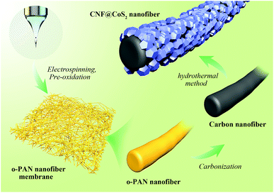
The preparation process of the CNF@CoS2 nanofiber membranes is schematically shown in Scheme 1. PAN nanofiber membranes were produced through a simple single-nozzle electrospinning technique. Typically, 1.0 g PAN was dissolved overnight in 10 mL DMF with vigorous stirring, forming a viscous homogenous solution. Then, it was sucked into a 5 mL syringe equipped with a stainless spinneret, which was positioned 18 cm away from the collector. When a high voltage of 20 kV was applied to the system, PAN nanofibers were generated and collected with a feeding rate of 0.25 mm min−1 as self-standing membrane. The pre-oxidization process was operated under 250 °C for 2 h with a heating rate of 1 °C min−1 in an air atmosphere to obtain oxidized-PAN (o-PAN) nanofiber membranes. Afterwards, they were carbonized in a nitrogen flow at 800 °C for 2 h to prepare the CNF membranes.The CNF@CoS2 core/sheath hybrid membranes were fabricated with a one-step hydrothermal method. First, the prepared CNF membranes were immersed in a bath of HNO3/H2O (1![[thin space (1/6-em)]](https://www.rsc.org/images/entities/char_2009.gif) :
:![[thin space (1/6-em)]](https://www.rsc.org/images/entities/char_2009.gif) 1 v/v) for 6 h to increase their hydrophilicity, and then washed with deionized water several times. After that, certain amounts of CoCl2·6H2O (i.e., 0.3, 1.0, and 3.0 mmol) and CS(NH2)2 (i.e., 1.0, 5.0, and 15.0 mmol, respectively) were dissolved in 36 mL deionized water with sonication for a few minutes. The solution was transferred to a 100 mL Teflon-lined stainless steel autoclave with a piece of acid-treated CNF membrane (2 × 2 cm2) immersed in the reaction solution. The autoclave was sealed and maintained at 180 °C for 17 h, and then cooled down to room temperature. Finally, the obtained hybrid membrane was rinsed with deionized water and dried at 70 °C for 6 h. The products were named CNF@CoS2-1, CNF@CoS2-3 and CNF@CoS2-9, respectively. Pure CoS2 was also synthesized via the same procedure without the addition of CNF membrane.
1 v/v) for 6 h to increase their hydrophilicity, and then washed with deionized water several times. After that, certain amounts of CoCl2·6H2O (i.e., 0.3, 1.0, and 3.0 mmol) and CS(NH2)2 (i.e., 1.0, 5.0, and 15.0 mmol, respectively) were dissolved in 36 mL deionized water with sonication for a few minutes. The solution was transferred to a 100 mL Teflon-lined stainless steel autoclave with a piece of acid-treated CNF membrane (2 × 2 cm2) immersed in the reaction solution. The autoclave was sealed and maintained at 180 °C for 17 h, and then cooled down to room temperature. Finally, the obtained hybrid membrane was rinsed with deionized water and dried at 70 °C for 6 h. The products were named CNF@CoS2-1, CNF@CoS2-3 and CNF@CoS2-9, respectively. Pure CoS2 was also synthesized via the same procedure without the addition of CNF membrane.
2.3. Characterization
The morphology of the products was observed using a field emission scanning electron microscope (FESEM, Ultra 55, Zeiss) at an acceleration voltage of 5 kV. X-ray diffraction (XRD) experiments were conducted on an X'Pert Pro X-ray diffractometer with Cu Kα radiation (λ = 0.1542 nm) under a voltage of 40 kV and a current of 40 mA. Thermogravimetric analysis (Pyris 1 TGA) was performed under an air flow from 100 °C to 900 °C at a heating rate of 20 °C min−1. X-ray photoelectron spectroscopy (XPS) analyses were made with a VG ESCALAB 220I-XL device and all XPS spectra were corrected using the C 1s line at 284.6 eV.2.4. Electrochemical measurements
Electrochemical tests were performed in a standard three-electrode setup using a CHI 660D electrochemical workstation (Shanghai Chenhua Instrument Co., China), where a graphite rod was used as the counter electrode, a saturated calomel electrode (SCE) as the reference electrode and a modified glassy carbon electrode (GCE) as the working electrode. A piece of pre-cut CNF@CoS2 core/sheath hybrid membrane was fixed onto the GCE using Nafion solution as a conductive binder, with a loading amount of 0.6–0.8 mg in a square shape of 3 × 3 mm2. Linear sweep voltammetry (LSV) was measured with a scan rate of 2 mV s−1 in 0.5 M H2SO4, 1.0 M KOH solution and 1.0 M potassium phosphate buffer solution (PBS). All of the potentials were calibrated to the reversible hydrogen electrode (RHE) by adding a value of (0.241 + 0.059 × pH) V. Tafel plots were obtained by plotting the polarization curves as the overpotential (η) versus log current density (log![[thin space (1/6-em)]](https://www.rsc.org/images/entities/char_2009.gif) j) to assess the HER kinetics. The linear portions of the Tafel plots fitted well to the Tafel equation (η = b
j) to assess the HER kinetics. The linear portions of the Tafel plots fitted well to the Tafel equation (η = b![[thin space (1/6-em)]](https://www.rsc.org/images/entities/char_2009.gif) log(j) + a, where b is the Tafel slope). The double-layer capacitance (Cdl) of the various products can be calculated from the cyclic voltammograms in the region of 0.15–0.25 V vs. RHE. By plotting Δj at 0.2 V vs. RHE against the scan rate, the slope is twice Cdl. Electrochemical impedance spectroscopic (EIS) measurements were carried out under various overpotentials in the frequency range from 106 Hz to 10−2 Hz with an amplitude of 5 mV. The electrocatalytic stability of the products was evaluated using the current–time response under a fixed overpotential for a period of time.
log(j) + a, where b is the Tafel slope). The double-layer capacitance (Cdl) of the various products can be calculated from the cyclic voltammograms in the region of 0.15–0.25 V vs. RHE. By plotting Δj at 0.2 V vs. RHE against the scan rate, the slope is twice Cdl. Electrochemical impedance spectroscopic (EIS) measurements were carried out under various overpotentials in the frequency range from 106 Hz to 10−2 Hz with an amplitude of 5 mV. The electrocatalytic stability of the products was evaluated using the current–time response under a fixed overpotential for a period of time.
3. Results and discussion
3.1. Morphology and structure of CNF@CoS2 core/sheath hybrid membranes
Electrospinning is a low-cost, scalable and versatile method to prepare nanofiber membranes with tunable nanostructures, large specific surface areas and good structural stability.34 As shown in Fig. S1,† the electrospun CNFs possess an average diameter of 300–400 nm and have smooth surfaces without defects. Such a randomly arranged structure forms an interconnected network, which can be utilized as an ideal carrier for the attachment of electrochemically active materials. In this work, CoS2 nanoparticles were decorated onto the CNF membranes using a one-step hydrothermal process. It can be clearly seen from Fig. 1A–C that all the nanofibers are uniformly covered with CoS2 nanoparticles in this overall view. However, as observed from images at high magnification (Fig. 1D–F), the morphology and size of the attached CoS2 nanoparticles show a great change on increasing the concentration of CoCl2·6H2O and CS(NH2)2. For CNF@CoS2-1, CoS2 nanoparticles have an angular shape with a random polyhedron structure. Furthermore, the average diameter of the hybrid nanofibers is rather large in size, up to nearly 1 μm. As shown in Fig. 1E, the CoS2 nanoparticles in CNF@CoS2-3 have a much smaller size compared with that in CNF@CoS2-1, along with a more homogeneous dimension. Such a nanoscaled structure with relatively small and even size may increase the effective electrocatalytic surface area, thus exerting a positive effect on the HER performance. EDS mapping images of the CNF@CoS2-3 hybrid (Fig. S2†) indicate the uniform distribution of Co and S elements, verifying the uniform growth of CoS2 on the CNF carrier. With an excessive amount of cobalt salt, the CoS2 particle size becomes even smaller for the CNF@CoS2-9 hybrid without such distinct angular edges (Fig. 1C, F and S3†). In addition, the CoS2 nanoparticles are so small (around 50–100 nm in diameter) that some part of them inevitably accumulate densely, which could impede effective contact between the electrolyte and the electrocatalytic active materials. For pure CoS2 without CNF carrier (Fig. S4†), the CoS2 particles self-aggregate to form large agglomerates, indicating the importance of the CNF carrier to effectively disperse CoS2 nanoparticles.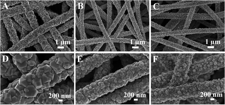 | ||
| Fig. 1 FESEM images of (A, D) CNF@CoS2-1, (B, E) CNF@CoS2-3, and (C, F) CNF@CoS2-9 hybrids at low and high magnifications. | ||
The surface chemical states of CNF@CoS2-3 hybrid were characterized using XPS as shown in Fig. 2A–C. The survey spectrum confirms the coexistence of C, Co, O and S elements within the hybrid without any detectable impurity. The high-resolution Co 2p spectrum exhibits two strong peaks located at 778.7 and 793.8 eV, corresponding to Co 2p3/2 and Co 2p1/2, respectively.35 In the high resolution S 2p spectrum, peaks at 162.9 eV and 164.1 eV are observed, referring to S 2p3/2 and S 2p1/2 of the divalent sulfide ions (S2−), respectively.36 For the XRD patterns in Fig. 2D, the CNF membrane displays a broad peak ranging from 20° to 30°, implying its amorphous structure. Both pure CoS2 and CNF@CoS2-3 display diffraction peaks at 2θ = 28.3°, 32.7°, 36.7°, 40.3°, 46.8° and 55.5°, which can be well indexed to the (111), (200), (210), (211), (220) and (311) planes of the cubic phase of CoS2 (JCPDS 41-1471), respectively.31 All the above results further demonstrate the successful preparation of the CNF@CoS2 hybrids.
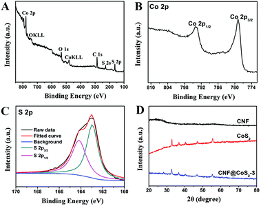 | ||
| Fig. 2 XPS spectra of the CNF@CoS2-3 hybrid: (A) survey spectrum, (B) high-resolution Co 2p spectrum, and (C) high-resolution S 2p spectrum. (D) XRD patterns of CNF, CoS2 and the CNF@CoS2-3 hybrid. | ||
The loading amount of CoS2 in different hybrids was studied using TGA analysis, as shown in Fig. 3. There exist several stages of weight change for pure CoS2, which correspond to different phase changes. When performed in an air flow, CoS2 begins to lose sulfur at 430 °C, which subsequently transforms to its stable form of metal sulfate.37–39 The products collected after thermal treatment at 700 °C and 900 °C were further investigated using XRD, as shown in Fig. S5.† The diffraction peaks at 2θ = 31.6°, 37.2°, 45.0°, 56.1°, 59.7° and 65.7° can be assigned to the (220), (311), (400), (422), (511) and (440) crystal planes of Co3O4 (JCPDS 42-1467), respectively, indicating that CoS2 has been oxidized completely at 900 °C.40,41 In contrast, although the product at 700 °C has some characteristic diffraction peaks of Co3O4, the peak intensities are far weaker than those at 900 °C. Furthermore, some additional peaks appear at 2θ = 25.2°, 34.7°, which correspond to the planes of CoSO4 (JCPDS 03-0843). As a result, when calcinated in air, CoS2 first loses sulfur, then changes to cobalt sulphate, and finally turns into pure Co3O4 at 900 °C. The TGA curve of CNF displays a huge weight loss from 430 °C to 680 °C, which results from its burning in air. As a result, the TGA process for the CNF@CoS2 hybrids combines the decomposition of CNF with the transformation of CoS2. To our surprise, it was found that the three CNF@CoS2 hybrids had the same residue weight at 900 °C, demonstrating that the loading ratios of the electroactive CoS2 remained almost the same, about 74.8 wt% in the hybrids (see ESI† for calculation details). This result indicates that the concentration of precursor has a great influence on the morphology instead of the loading amount.
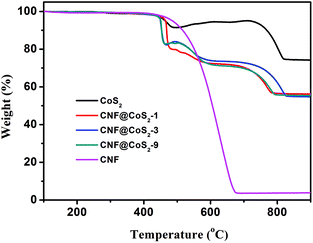 | ||
| Fig. 3 TGA curves of CNF, CoS2 and the CNF@CoS2 hybrids measured in an air flow from 100 °C to 900 °C. | ||
3.2. All-pH-value HER performance of CNF@CoS2 hybrids
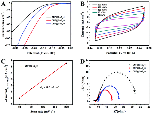
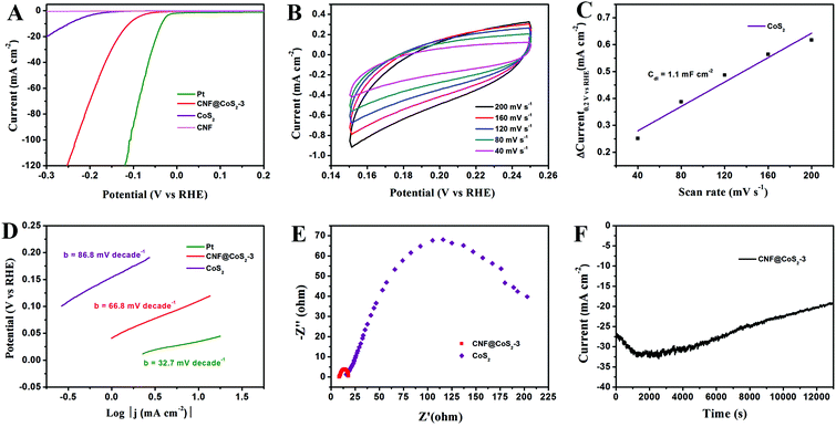
The electrocatalytic activity of the CNF@CoS2 hybrids was first investigated in an acid medium of 0.5 M H2SO4 solution with a three-electrode setup at a scan rate of 2 mV s−1. The LSV curves for the CNF@CoS2 hybrids with different morphologies are shown in Fig. 4A. Two key points are utilized to evaluate the performance of the HER electrocatalysts from the LSV curves. One lies in the overpotential (η), which is the difference between the applied and thermodynamic potential for a given electrochemical reaction. The other point refers to the electrochemical current density, indicating the output of the electrocatalytically evolved hydrogen. Naturally, an excellent HER catalyst is capable of generating a large current density under a low overpotential, i.e., more hydrogen can be produced using less energy if the reaction is undertaken using a well-performing electrocatalyst.42 Therefore, it can be deduced from Fig. 4A that among all the CNF@CoS2 hybrids, the CNF@CoS2-3 hybrid displays the best electrocatalytic activity, with an onset overpotential of 40 mV. The other two LSV curves are more or less negatively shifted compared with that of the CNF@CoS2-3 hybrid, implying an inferior HER performance. Furthermore, the CNF@CoS2-3 hybrid also has an apparent current density (j) of 10.0 mA cm−2 at a low overpotential (η) of 110 mV, compared with 166 mV required for CNF@CoS2-1 and 143 mV for the CNF@CoS2-9 hybrid. A possible reason for the difference in their electrocatalytic activities can be speculated from the morphological changes discussed above. Compared to the other two hybrids, the CNF@CoS2-3 hybrid possesses an optimal hierarchical structure with uniformly distributed CoS2 nanoparticles of a relatively smaller size without severe agglomeration, which may offer a large contact area between electrolyte and catalyst, thus facilitating ion/electron transfer, leading to the best HER performance. This hypothesis was further confirmed from the electrochemical double-layer capacitance (Cdl) and electrochemical impedance spectra (EIS). Cdl measurements were carried out using cyclic voltammetry (CV) tests to estimate the effective surface area of the solid–liquid interface.43 It can be observed from Fig. 4B and C that the CNF@CoS2-3 hybrid exhibits a larger Cdl of 17.5 mF cm−2 than those of its counterparts (Fig. S6†), indicating a higher exposure of the electrocatalytic sites, thus contributing to its excellent HER performance. Fig. 4D displays the Nyquist plots of the different CNF@CoS2 hybrids obtained under the same overpotential of 170 mV. Rct represents the charge transfer resistance, which corresponds to the semicircle of the Nyquist plots. It can be clearly observed that CNF@CoS2-3 shows the lowest Rct of 9.9 Ω, in comparison with 12.5 Ω for CNF@CoS2-9 and 22.9 Ω for the CNF@CoS2-1 hybrid. Measured under the same proton reduction potential, a lower Rct value reflects a more effective electron transfer in the CNF@CoS2-3 hybrid, leading to more efficient hydrogen evolution.44 EIS responses of the CNF@CoS2-3 hybrid at various overpotentials were also tested, as shown in Fig. S7.†Rct of 28.9 Ω, 9.9 Ω and 6.4 Ω under overpotentials of 120, 170 and 220 mV were found, respectively. This reveals that with increasing overpotential, more efficient hydrogen generation takes place, along with a more rapid electron transfer.Further comparison of the HER performance between pure CNF, CoS2, the CNF@CoS2-3 hybrid and commercially available Pt catalyst was also made. As shown in Fig. 5A, the Pt catalyst exhibits a superb HER activity, with a near zero onset potential and a large current density, while pure CNF hardly displays any catalytic performance. Although pure CoS2 agglomerates exhibit a non-negligible electrocatalytic performance, the onset potential and current density are far inferior to those of the CNF@CoS2-3 hybrid, which is due to its serious aggregation inhibiting the efficient exposure of its electrocatalytic sites. As confirmed from the analysis of Cdl, the catalytically active surface area of CNF@CoS2-3 (17.5 mF cm−2 in Fig. 4B and C) is over ten times larger than that of pure CoS2 (1.3 mF cm−2 in Fig. 5B and C). Such a huge difference between the hybrid and pure electrocatalytic materials strongly supports the importance of constructing a hierarchical structure with exposed HER active sites on a nanoscale size. The corresponding Tafel plots are shown in Fig. 5D. As is well known, the reaction mechanism of a catalyst can be deduced from its Tafel slope, which is determined from the inherent properties of the catalyst. For CNF@CoS2-3 measured in 0.5 M H2SO4, the Tafel slope is calculated to be 66.8 mV per decade, suggesting that the HER activity occurs through a Volmer–Heyrovsky mechanism, in which fast discharge of a proton takes place, followed by a rate-limiting electrochemical recombination with an additional proton. Moreover, it should be noted that the Tafel slope of the CNF@CoS2-3 hybrid is lower than that of pure CoS2 (86.8 mV per decade), indicating a higher HER efficiency. This result can be further explained using the Rct from the EIS analysis, as shown in Fig. 5E. On the one hand, the semicircle of pure CoS2 is far larger than that of the CNF@CoS2-3 hybrid, demonstrating a higher charge transfer resistance. On the other hand, the solution resistance (Rs), a value that can be obtained from the intersection of the curves at the real axis in the range of the high frequency region, displays the same tendency (8.2 Ω for the CNF@CoS2-3 hybrid and 15.6 Ω for pure CoS2). In terms of the cycling stability in 0.5 M H2SO4 solution, the CNF@CoS2-3 hybrid displays a slight fluctuation in HER performance, with the response current first increasing over 2000 s, and then decreasing later (Fig. 5F). Consequently, the morphology of the CNF@CoS2-3 hybrid after cycling for 2000 s was characterized, as shown in Fig. S8.† It can be observed that no obvious change occurs in the morphology after cycling for 2000 s. The increase in HER activity may be attributed to the activation process at the beginning, and this similar phenomenon has been reported in previous studies.36,42,53 For the later decrease in current density, a possible reason may be due to the partial loss of the electrocatalytically active sites of the CNF@CoS2-3 hybrid during the violent bubble accumulation and release process, which can be further proved from its morphology after the whole cycling test (Fig. S9†). However, it is worth mentioning that despite the partial collapse, the CoS2 nanoparticles still generally well-covered the surface of the CNF nanofibers after the cycling test, demonstrating that the CNF carrier plays an important role in stabilizing the structure. In contrast, pure CoS2 particles display a huge decline in electrocatalytic activity (Fig. S10†). All the above results clearly verify that the HER performance of the hybrid materials is better than that of the pure aggregate, demonstrating the rational design of the hybrid product, whose electrocatalytic performance is also remarkable when compared to some previous studies in acid media, as listed in Table 1.
| Sample | η 10 (mV) | η 20 (mV) | η 100 (mV) | Onset overpotential (mV) | Ref. |
|---|---|---|---|---|---|
| η 10: overpotential (η) for current density (j) of 10.0 mA cm−2; η20: η for j = 20.0 mA cm−2; η100: η for j = 100.0 mA cm−2. | |||||
| CoSe2/carbon fiber | 137 | 150 | 181 | 28 | |
| Co2P nanorod | 134 | 167 | 70 | 45 | |
| CoS2/rGO | 143 | 173 | 346 | 46 | |
| Co9S8@C | 240 | 40 | |||
| Co9S8@MoS2/CNFs | 190 | 64 | 47 | ||
| CoS2 nanowire | 145 | 75 | 31 | ||
| CoS2/rGO-CNT | 142 | 153 | 178 | 29 | |
| Co–N-rich CNTs | 260 | 48 | |||
| MoSx-G | 183 | 130 | 49 | ||
| MoP | 135 | 167 | 50 | 50 | |
| WS2/rGO | 229 | 51 | |||
| CNT@MoSe2 | 178 | 70 | 52 | ||
| CNF@CoS2 | 110 | 133 | 232 | 40 | This work |
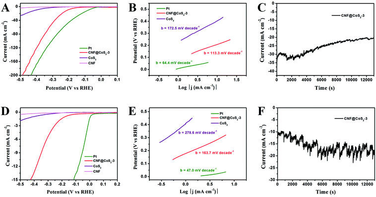
The HER performance of the CNF@CoS2-3 hybrid was further examined in 1.0 M KOH solution and 1.0 M PBS solution to evaluate its activity as an all-pH-range electrocatalyst (Fig. 6). In alkaline medium, the CNF@CoS2-3 hybrid exhibits an onset overpotential of 130 mV, accompanied by significant hydrogen evolution (j = 10.0 mA cm−2) at a voltage of −207 mV. Furthermore, the Tafel slope of the CNF@CoS2-3 hybrid (113.3 mV per decade) is also relatively smaller than that of pure CoS2 (172.5 mV per decade) in KOH solution, implying a faster HER process with higher efficiency. When applied in neutral conditions, it could be easily found that all the electrocatalysts have a much poorer activity than those in acid and alkaline electrolytes. The CNF@CoS2-3 hybrid catalyst exhibits an onset potential of −130 mV, a Tafel slope of 163.7 mV per decade, and a current density (j) of 10.0 mA cm−2 at an overpotential (η) of 360 mV. In addition, the working stability is another important criterion when making an excellent electrocatalyst. Fig. 6C and F depict the current–time (I–t) curves of the CNF@CoS2-3 hybrid catalyzed HER under a constant overpotential of 0.27 V in KOH and 0.50 V in PBS, respectively, which also exhibit good cycling performance. Moreover, taking further insight from the I–t curves obtained using different electrolytes, it can be seen that the serrated waves of the I–t curve obtained in PBS solution are more violent than those in H2SO4 and KOH solutions, indicating that the CNF@CoS2-3 hybrid is less effective in driving H2 (g) bubble release in neutral media, which can be attributed to different HER mechanisms in different electrolyte media.32 In addition, it is speculated that these accumulated H2 (g) bubbles can generate an effective protective layer separating the electrocatalyst from the neutral electrolyte, thus periodically hindering the dissolution or collapse of the catalyst, leading to an enhanced stability compared with that in acid and alkaline electrolytes.
4. Conclusions
In summary, CNF@CoS2 core/sheath hybrids with different morphologies were prepared through a combination of electrospinning and hydrothermal methods for use as HER electrocatalysts in all-pH-value conditions. A hierarchical structure is facilely constructed with nanosized CoS2 particles evenly distributed on the CNFs, thus effectively preventing self-agglomeration of electroactive CoS2. In addition, the attached CoS2 nanoparticles display different morphologies on tuning the precursor concentration, but their loading amounts remain the same. The differences in morphology have a huge impact on the electrocatalytic performance, which can be attributed to the differences in the exposure of the efficient electroactive sites. Owing to the synergistic effects between the 3D CNF carrier and the electrocatalytically active CoS2 nanoparticles, the optimal CNF@CoS2 hybrid exhibits an excellent all-pH HER performance, with a low onset potential of −40 mV, a small Tafel slope of 66.8 mV per decade and a large current density (10.0 mA cm−2 at η = 110 mV) in acid media, as well as remarkable activities in alkaline and neutral media.Acknowledgements
The authors are grateful for the financial support from the National Natural Science Foundation of China (51125011, 51373037, 51433001).Notes and references
- Y. Jiao, Y. Zheng, M. Jaroniec and S. Z. Qiao, Chem. Soc. Rev., 2015, 44, 2060–2086 RSC.
- M. Zeng and Y. G. Li, J. Mater. Chem. A, 2015, 3, 14942–14962 CAS.
- Y. Yan, B. Y. Xia, Z. C. Xu and X. Wang, ACS Catal., 2014, 4, 1693–1705 CrossRef CAS.
- M. Jiang, Y. J. Li, Z. Y. Lu, X. M. Sun and X. Duan, Inorg. Chem. Front., 2016, 3, 630–634 RSC.
- C. G. Morales-Guio, L. A. Stern and X. L. Hu, Chem. Soc. Rev., 2014, 43, 6555–6569 RSC.
- F. M. Wang, T. A. Shifa, X. Y. Zhan, Y. Huang, K. L. Liu, Z. Z. Cheng, C. Jiang and J. He, Nanoscale, 2015, 7, 19764–19788 RSC.
- Q. P. Lu, Y. F. Yu, Q. L. Ma, B. Chen and H. Zhang, Adv. Mater., 2016, 28, 1917–1933 CrossRef CAS PubMed.
- J. Z. Chen, X. J. Wu, L. S. Yin, B. Li, X. Hong, Z. X. Fan, B. Chen, C. Xue and H. Zhang, Angew. Chem., Int. Ed., 2015, 54, 1210–1214 CrossRef CAS PubMed.
- C. B. Ma, X. Y. Qi, B. Chen, S. Y. Bao, Z. Y. Yin, X. J. Wu, Z. M. Luo, J. Wei, H. L. Zhang and H. Zhang, Nanoscale, 2014, 6, 5624–5629 RSC.
- Z. Y. Zeng, C. L. Tan, X. Huang, S. Y. Bao and H. Zhang, Energy Environ. Sci., 2014, 7, 797–803 CAS.
- J. J. Duan, S. Chen, B. A. Chambers, G. G. Andersson and S. Z. Qiao, Adv. Mater., 2015, 27, 4234–4241 CrossRef CAS PubMed.
- Y. P. Huang, Y. E. Miao, J. Fu, S. Y. Mo, C. Wei and T. X. Liu, J. Mater. Chem. A, 2015, 3, 16263–16271 CAS.
- H. Zhang, ACS Nano, 2015, 9, 9451–9469 CrossRef CAS PubMed.
- C. L. Tan and H. Zhang, Chem. Soc. Rev., 2015, 44, 2713–2731 RSC.
- X. Huang, C. L. Tan, Z. Y. Yin and H. Zhang, Adv. Mater., 2014, 26, 2185–2204 CrossRef CAS PubMed.
- H. Li, J. Wu, Z. Y. Yin and H. Zhang, Acc. Chem. Res., 2014, 47, 1067–1075 CrossRef CAS PubMed.
- Z. Q. Liu, H. Y. Zhao, N. Li, Y. Zhang, X. Y. Zhang and Y. P. Du, Inorg. Chem. Front., 2016, 3, 313–319 RSC.
- Y. Yang, S. T. Wang, J. C. Zhang, H. Y. Li, Z. L. Tang and X. Wang, Inorg. Chem. Front., 2015, 2, 931–937 RSC.
- X. Zhang, Z. C. Lai, C. L. Tan and H. Zhang, Angew. Chem., Int. Ed., 2016, 55, 8816–8838 CrossRef CAS PubMed.
- S. F. Matthew, A. L. Mark, D. Qi, S. K. Nicholas and J. Song, J. Phys. Chem. C, 2014, 118, 21347–21356 Search PubMed.
- X. Y. Yu, L. Yu and X. W. Lou, Adv. Energy Mater., 2016, 6, 1501333 CrossRef.
- J. S. Chen, J. Ren, M. Shalom, T. Fellinger and M. Antonietti, ACS Appl. Mater. Interfaces, 2016, 8, 5509–5516 CAS.
- X. X. Zou and Y. Zhang, Chem. Soc. Rev., 2015, 44, 5148–5180 RSC.
- C. H. Lin, C. L. Chen and J. H. Wang, J. Phys. Chem. C, 2011, 115, 18582–18588 CAS.
- Y. Zheng, Y. Jiao, M. Jaroniec and S. Z. Qiao, Angew. Chem., Int. Ed., 2015, 54, 52–65 CrossRef CAS PubMed.
- B. You, N. Jiang and Y. J. Sun, Inorg. Chem. Front., 2016, 3, 279–285 RSC.
- D. S. Kong, J. J. Cha, H. T. Wang, H. R. Lee and Y. Cui, Energy Environ. Sci., 2013, 6, 3553–3558 CAS.
- D. S. Kong, H. T. Wang, Z. Y. Lu and Y. Cui, J. Am. Chem. Soc., 2014, 136, 4897–4900 CrossRef CAS PubMed.
- S. J. Peng, L. L. Li, X. P. Han, W. P. Sun, M. Srinivasan, S. G. Mhaisalkar, F. Y. Cheng, Q. Y. Yan, J. Chen and S. Ramakrishna, Angew. Chem., Int. Ed., 2014, 53, 12594–12599 CAS.
- B. You, N. Jiang, M. L. Sheng and Y. J. Sun, Chem. Commun., 2015, 51, 4252–4255 RSC.
- M. S. Faber, R. Dziedzic, M. A. Lukowski, N. S. Kaiser, Q. Ding and S. Jin, J. Am. Chem. Soc., 2014, 136, 10053–10061 CrossRef CAS PubMed.
- F. Safizadeh, E. Ghali and G. Houlachi, Int. J. Hydrogen Energy, 2015, 40, 256–274 CrossRef CAS.
- Y. J. Sun, C. Liu, D. C. Grauer, J. Yano, J. R. Long, P. D. Yang and C. J. Chang, J. Am. Chem. Soc., 2013, 135, 17699–17702 CrossRef CAS PubMed.
- Z. Y. Xiong, X. Y. Kong, Z. X. Guo and J. Yu, Chin. J. Polym. Sci., 2015, 33, 1234–1244 CrossRef CAS.
- Y. Ji, X. Y. Liu, W. Liu, Y. Wang, H. D. Zhang, M. Yang, X. F. Wang, X. D. Zhao and S. H. Feng, RSC Adv., 2014, 4, 50220–50225 RSC.
- C. B. Ouyang, X. Wang and S. Y. Wang, Chem. Commun., 2015, 51, 14160–14163 RSC.
- J. H. Tang, J. F. Shen, N. Li and M. X. Ye, Ceram. Int., 2014, 40, 15411–15419 CrossRef CAS.
- B. Wang, J. S. Park, D. W. Su, C. Y. Wang, H. Ahn and G. X. Wang, J. Mater. Chem., 2012, 22, 15750–15756 RSC.
- J. B. Chung, Z. D. Ziang and J. S. Chung, Environ. Sci. Technol., 2002, 36, 3025–3029 CrossRef CAS PubMed.
- L. L. Feng, G. D. Li, Y. P. Liu, Y. Y. Wu, H. Chen, Y. Wang, Y. C. Zou, D. J. Wang and X. X. Zou, ACS Appl. Mater. Interfaces, 2015, 7, 980–988 CAS.
- S. Wan, Y. P. Liu, G. D. Li, X. T. Li, D. J. Wang and X. X. Zou, Catal. Sci. Technol., 2016, 6, 4545–4553 CAS.
- D. Y. Wang, M. Gong, H. L. Chou, C. J. Pan, H. A. Chen, Y. P. Wu, M. C. Lin, M. Y. Guan, J. Yang, C. W. Chen, Y. L. Wang, B. J. Hwang, C. C. Chen and H. J. Dai, J. Am. Chem. Soc., 2015, 137, 1587–1592 CrossRef CAS PubMed.
- Y. Zhao, F. Zhao, X. P. Wang, C. Y. Xu, Z. P. Zhang, G. Q. Shi and L. T. Qu, Angew. Chem., Int. Ed., 2014, 53, 13934–13939 CrossRef CAS PubMed.
- K. Xu, F. M. Wang, Z. X. Wang, X. Y. Zhan, Q. S. Wang, Z. Z. Cheng, M. Safdar and J. He, ACS Nano, 2014, 8, 8468–8476 CrossRef CAS PubMed.
- Z. Huang, Z. Chen, Z. Chen, C. Lv, M. G. Humphrey and C. Zhang, Nano Energy, 2014, 9, 373–382 CrossRef CAS.
- W. Xing, Y. Zhang, Q. Z. Xue and Z. F. Yan, Nanoscale Res. Lett., 2015, 10, 1–6 CrossRef CAS PubMed.
- H. Zhu, J. F. Zhang, R. P. Yanzhang, M. L. Du, Q. F. Wang, G. H. Gao, J. D. Wu, G. M. Wu, M. Zhang, B. Liu, J. M. Yao and X. W. Zhang, Adv. Mater., 2015, 27, 4752–4759 CrossRef CAS PubMed.
- X. X. Zou, X. X. Huang, A. Goswami, R. Silva, B. R. Sathe, E. Mikmeková and T. Asefa, Angew. Chem., 2014, 126, 4461–4465 CrossRef.
- Z. H. Pu, Q. Liu, A. M. Asiri, A. Y. Obaid and X. P. Sun, J. Power Sources, 2014, 263, 181–185 CrossRef CAS.
- P. Xiao, M. A. Sk, L. Thia, X. M. Ge, R. J. Lim, J. Y. Wang, K. H. Lim and X. Wang, Energy Environ. Sci., 2014, 7, 2624–2629 CAS.
- T. A. Shifa, F. M. Wang, Z. Z. Cheng, X. Y. Zhan, Z. X. Wang, K. L. Liu, M. Safdar, L. F. Sun and J. He, Nanoscale, 2015, 7, 14760–14765 RSC.
- Y. P. Huang, H. Y. Lu, H. H. Gu, J. Fu, S. Y. Mo, C. Wei, Y. E. Miao and T. X. Liu, Nanoscale, 2015, 7, 18595–18602 RSC.
- F. H. Saadi, A. I. Carim, J. M. Velazquez, J. H. Baricuatro, C. C. L. McCrory, M. P. Soriaga and N. S. Lewis, ACS Catal., 2014, 4, 2866–2873 CrossRef CAS.
Footnote |
| † Electronic supplementary information (ESI) available: Calculation of the loading ratio of CoS2 in the CNF@CoS2 hybrids; FESEM image of CNF; FESEM image of the CNF@CoS2-3 hybrid and its corresponding EDS mapping images; FESEM image of the CNF@CoS2-9 hybrid at high magnification; FESEM image of CoS2; XRD patterns of the products collected after thermal treatment at 700 °C and 900 °C; Plots showing the extraction of the double layer capacitance for the CNF@CoS2-1 and CNF@CoS2-9 hybrids; Nyquist plots of the CNF@CoS2-3 hybrid at various overpotentials in 0.5 M H2SO4; FESEM image of the CNF@CoS2-3 hybrid after the cycling test; Cycling stability of the pure CoS2 modified GCE. See DOI: 10.1039/c6qi00229c |
| This journal is © the Partner Organisations 2016 |

