DOI:
10.1039/C6QI00194G
(Research Article)
Inorg. Chem. Front., 2016,
3, 1190-1197
Coating a N-doped TiO2 shell on dually sensitized upconversion nanocrystals to provide NIR-enhanced photocatalysts for efficient utilization of upconverted emissions†
Received
21st June 2016
, Accepted 13th July 2016
First published on 15th July 2016
Abstract
Development of TiO2-based photocatalysts capable of utilizing NIR light is very important for practical applications using the solar spectrum. The combination of upconversion nanocrystals (UCNs) with TiO2 is a promising route for activation of photocatalysts under NIR irradiation. Here we propose integration of dually sensitized UCNs with N-doped TiO2 with a core–shell–shell structure. In such composite photocatalysts, the core–shell UCNs exhibit enhanced UC emissions in response to two NIR bands and all the UC emissions can be utilized by the N-TiO2 shell. The doping manner of the UCN cores and the N-doping level of the TiO2 shell both have a significant effect on the photocatalytic activity. Our results suggest that rational design of the configuration of the component materials is a feasible way to improve the photocatalytic activity of such UCN/TiO2 nanocomposites.
1. Introduction
TiO2-based nanomaterials are very important photocatalysts for both scientific research and industrial applications, owing to their strong oxidizing power, extraordinary chemical stability, environmental benignity, and biocompatibility.1–7 However, one large limitation of TiO2 is its wide band gap of 3.2 eV (anatase phase), which means it can only be activated by ultraviolet (UV) light.8 As we know, UV light only occupies 5% of the solar spectrum, whereas most of the solar energy is located in the visible region (Vis, ca. 48%) and near-infrared region (NIR, ca. 47%), which are still difficult to utilize with pure TiO2.9 In recent decades, many strategies have been developed to broaden the absorption of TiO2 such as metal or non-metal doping, the deposition of noble metals, and coupling with other semiconductors.10–12 Inspiringly, a few approaches have successfully extended the TiO2 absorption to the Vis region. Nevertheless, how to make use of NIR light for TiO2 photocatalysis is still rarely explored. The development of TiO2-based photocatalysts capable of utilizing not only UV/Vis light but also NIR light is of great importance.
Upconversion nanocrystals (UCNs) can convert low-energy NIR photons to high-energy UV and/or Vis photons so that they can serve as a light transducer to activate TiO2 for photocatalysis under NIR light.13,14 Recently, a few attempts have been made to synthesize UCN/TiO2 composite materials for building such NIR-driven photocatalysts. For example, lanthanide-doped YF3, LaF3 and CaF2 NCs have been coated with a TiO2 shell and showed promising applications in both dye-sensitised solar cells (DSSCs) and photocatalytic degradation.15–18 For practical industrial applications, the use of high-quality UCNs with a high UC efficiency is pivotal since the UCNs are the most influential component part in such hybrid photocatalysts. As one of the best UC materials, lanthanide-doped NaYF4 is undoubtedly a preferred choice for this purpose in comparison with other UCNs.19,20 Several groups have attempted the synthesis of NaYF4@TiO2 particles, but the implemented NaYF4 NCs were either in the α-phase with a lower UC efficiency or in the β-phase with a microscale size, which limited their potential in photocatalysis.21–23 To employ uniform and regular β-NaYF4 as the UC core, Zhao et al. utilized a SiO2 shell as an intermediate layer for the TiO2 coating;24 we also developed a surfactant-mediated approach to directly coat a TiO2 shell on hydrophobic NaYF4 NCs.25
Despite the above progress in particle synthesis, the photocatalytic activity of the above developed UCN/TiO2 is still low and far from useful for practical applications. It still remains a great challenge to fully explore the potential of both the component materials in the nanocomposites for achieving a desirable performance. On one hand, the TiO2 shell can only make use of the UV emissions from the NaYF4 NCs in the reported samples, lacking a response to the upconverted Vis emissions. On the other hand, most NaYF4-based UCNs were solely sensitized with Yb3+ ions, which can only absorb the NIR light around 980 nm. The construction of UCN/TiO2 nanocomposites with a high UC efficiency, wide NIR response and full utilization of the UC emissions is thus highly demanded.
Nd3+ ions have a large absorption cross section around 808 nm, and they can efficiently transfer energy to Yb3+ ions and subsequently to activator ions such as Tm3+.26–28 Codoped with Nd3+ and Yb3+ ions, the NaYF4 NCs can be dually sensitized to two NIR bands and give strong UC emissions in both the UV and Vis region after Tm3+ doping. In this work, we synthesized NaYF4:Yb,Tm@NaYF4:Yb,Nd (termed as Tm/Yb@Yb/Nd) NCs in which the activator ions and sensitizer ions are spatially separated in the core–shell structure. Such a core–shell configuration can not only enhance the UC efficiency of the core NCs but can also facilitate the doping of high-level sensitizer ions in the shell for a wide and efficient NIR absorption. At the same time, we also directly deposit a N-doped TiO2 shell on these core–shell UCNs for fully receiving the upconverted UV and Vis emissions. The developed Tm/Yb@Yb/Nd@N-TiO2 nanoparticles (NPs) can not only work under a single UV/Vis/NIR band but also can show significantly enhanced activity under the full solar spectrum. The effects of the core–shell configuration and doping manner in the NaYF4@NaYF4 core and the doping amount of the N elements in the TiO2 shell on the photocatalytic activity have been systematically investigated. Our work suggests that there is still plenty of room to enhance the photocatalytic activity of UCN/TiO2 nanocomposites by rationally designing and configuring the component materials in the hybrid photocatalysts.
2. Experimental
2.1 Chemicals
YCl3, YbCl3, TmCl3, NdCl3, oleic acid (OA), octadecene (ODE), cetyltrimethyl ammonium bromide (CTAB) and titanium diisopropoxide bis(acetylacetonate) (TDAA) were purchased from Sigma-Aldrich and used as received. NaOH, NH4F, ammonia (28 wt%), urea, cyclohexane, isopropanol and absolute ethanol were purchased from local suppliers. All the reagents were of analytical grade.
2.2 Synthesis of Tm/Yb@Yb/Nd core–shell NCs
High-quality NaYF4:Yb(20%),Tm(0.5%) NCs were synthesized with a user-friendly protocol according to a previous literature report.29 In brief, stoichiometric YCl3, YbCl3 and TmCl3 were dissolved in a mixed solution of octadecene and oleic acid at 160 °C. Then, NH4F and NaOH in methanol were added into the solution and the methanol phase was evaporated. After being degassed at 100 °C for 10 min, the solution was heated to 300 °C and the temperature maintained for 1 h. After washing with methanol and water, the NCs could be collected from the solution using a centrifuge. Using the prepared NCs as seeds, a NaYF4 shell doped with Yb3+ (10%) and Nd3+ (10%) was created on their surface with a seed-mediated growing approach.30,31 In a typical synthesis, 0.8 mmol YCl3, 0.1 mmol YbCl3 and 0.1 mmol NdCl3 were dissolved in 6 mL of oleic acid and 15 mL of 1-octadecene at 140 °C. Then, 1 mmol of the NaYF4:Yb,Tm NCs in 10 mL of hexane was added and the hexane phase was removed by evaporation. After that, a solution of 4 mmol NH4F and 2.5 mmol NaOH in 10 mL of methanol was added and the mixture was kept at room-temperature for 30 min. After evaporating the methanol and degassing at 100 °C for 15 min, the solution was heated to 280 °C and the temperature was maintained for 1 h under Ar protection. On cooling down to room temperature, the prepared core–shell NCs were precipitated with acetone and centrifuged out of the solution. After washing with ethanol and water twice, these NCs were dispersed in cyclohexane for further use.
2.3 Surface modification of hydrophobic Tm/Yb@Yb/Nd NCs
The prepared Tm/Yb@Yb/Nd NCs had an oleate-capped surface and they were initially dispersed in cyclohexane with a concentration of 0.1 M. For covering these NCs with a surfactant layer, a reverse-micelle method was adapted. In a typical process, 1 mL of the NCs in cyclohexane, 0.05 g of cetyltrimethyl ammonium bromide (CTAB) and 20 mL of deionized (DI) water were mixed in a 50 mL flask under magnetic stirring. Then, the flask was put into a water-bath and slowly heated to 80 °C. Upon slowly evaporating the cyclohexane, the appearance of the mixed solution gradually changed from milky to transparent. After keeping the mixture at 80 °C for 10 min, the transparent solution was removed from the water-bath and cooled down to room-temperature. The surfactant-modified NCs were then collected from the solution using a centrifuge at a speed of 8000 rpm and the obtained sample was finally dispersed in 10 mL isopropanol (IPA).
2.4 Synthesis of Tm/Yb@Yb/Nd@N-TiO2 NPs
First, 10 mL of the surfactant-modified Tm/Yb@Yb/Nd NCs (in IPA), 2.5 mL of DI water and 0.3 mL of ammonia (28 wt%) were mixed in a 25 mL flask under magnetic stirring. Then, 10 mL of a titanium diisopropoxide bis(acetylacetonate) (TDAA) solution (10 mM in IPA) was slowly injected into the mixed solution with a syringe pump. The solution was then aged in the flask for 12 h at room temperature. The product was collected from the solution using a centrifuge at a speed of 6000 rpm. After washing with ethanol twice, the product was dispersed in a mixed solution of 4 mL ethanol, 1 mL DI water and 0.03 g urea. The solution was then put in an oven and slowly evaporated below 100 °C. After that, the solid powder was annealed at 500 °C for 3 h in a muffle furnace under an air atmosphere. Different amounts of the N element were doped into the Tm/Yb@Yb/Nd@ TiO2 sample by changing the addition amount of the urea (0.01 g–0.035 g). According to the weight ratio of the urea to Tm/Yb@Nd/Yb@TiO2, these samples were termed as TiN-0.5, TiN-1, TiN-1.25, TiN-1.5 and TiN-1.75, respectively. The actual amount of the doped N elements in each sample was determined using XPS analysis and the data are listed in Table S1.†
2.5 Characterization
Powder X-ray diffraction (XRD) was carried out using a Philips X'Pert Pro X-ray diffractometer equipped with Cu Kα radiation. Transmission electron microscopy (TEM) was performed with a JEOL 2010F TEM. Energy dispersive X-ray spectrometry (EDS) was performed with a spectroscope present on the transmission electron microscope, which was used for the elemental analysis. X-ray photoelectron spectra (XPS) were collected using an ESCAlab MKII X-ray photoelectron spectrometer. UV-Vis absorption spectra were obtained using a Shimadzu UV-2450 UV-Vis spectrophotometer. Fluorescence spectra were acquired with a Hitachi F-7000 spectrometer equipped with two commercial NIR lasers (980 nm and 808 nm for each with a power density of 50 mW cm−2).
2.6 Photocatalytic measurements
The photocatalytic activities of the Tm/Yb@Yb/Nd@N-TiO2 NPs were evaluated through the degradation of a RhB solution under irradiation with a Xe lamp (PLS-SXE300, Trusttech Co., Ltd, Beijing). Different irradiation bands were obtained through rationally choosing the following filters: UV band-pass (300–420 nm), Vis band-pass (420–780 nm) and NIR band-pass (780–2500 nm). In a typical process, 20 mg of the as-prepared product was put into 50 mL of a RhB solution (5 × 10⁻⁴ M) in a beaker. Then, the solution was stirred for 12 h in the dark to reach an adsorption–desorption equilibrium between the NPs and the dye solution. Subsequently, the beaker was exposed to irradiation using the Xe lamp (100 mW cm−2) accompanied by a suitable filter for a certain period of time. Aliquots were intermittently collected at given time intervals for measuring the concentration of RhB by UV-Vis spectroscopy.
3. Results and discussion
3.1 TEM morphologies of the prepared samples
TEM images of the prepared samples from the primitive NaYF4:Yb,Tm NCs to the final Tm/Yb@Yb/Nd@TiO2 NPs are shown in Fig. 1. From Fig. 1A, one can see that the prepared NaYF4:Yb,Tm NCs are monodisperse nanoscale particles with a narrow size distribution. The diameter of these NCs is about 32 nm. Due to the existence of long hydrophobic chains on their surface, many NCs are easily self-assembled on a copper grid.29,32 After epitaxial growth of a NaYF4:Yb,Nd shell on these NCs, the newly obtained core–shell UCNs still possess a uniform size and shape. The size of these UCNs obviously increases from 32 nm to 40 nm (Fig. 1B). At the same time, these UCNs show an apparent polyhedral shape with a hexagonal appearance in the front plane, which is a characteristic morphology of β-phase NaYF4 NCs.13,33 After modifying these core–shell Tm/Yb@Yb/Nd NCs with a layer of CTAB surfactant, they can be directly dispersed in water or some organic solvents such as IPA. Under TEM observation, the CTAB-modified UCNs show a similar morphology to those before modification (see Fig. 1C), implying that the surface-modification process has negligible effect on the size and shape of these particles. This result is easily understood since the modification process was carried out under mild conditions and the net result was the addition of a layer of surfactant on the particles.
 |
| | Fig. 1 TEM images of the prepared samples: (1) NaYF4:Yb,Tm NCs; (2) Tm/Yb@Yb/Nd NCs; (C) CTAB-modified Tm/Yb@Yb/Nd NCs; (D) Tm/Yb@Yb/Nd@a-TiO2 (a-, amorphous); (E, F) Tm/Yb@Yb/Nd@N-TiO2 with different magnifications. Scale bar in the inset of (D) is 10 nm. | |
When an amorphous TiO2 layer was coated on the Tm/Yb@Yb/Nd NCs through a sol–gel process, an obvious heterogeneous shell appeared on the particle surface (Fig. 1D). The average thickness of the TiO2 shell was around 10 nm (see inset of Fig. 1D). Due to cross-linking of the hydrolyzed TDAA molecules between the particles, some particles are likely to aggregate together. After being doped with N elements and annealled at 500 °C, the amorphous TiO2 shell became highly crystalline. At the same time, the TiO2 layer became a little porous due to complete decomposition of residual TDAA molecules and crystallization of the amorphous species (Fig. 1E and S1†). At the interface between the NaYF4:Yb,Nd shell and N-TiO2 layer, obvious different lattice fringes can be observed (see Fig. 1F). The inner fringes are about 0.52 nm, corresponding to the (100) plane of the β-NaYF4 crystal, and the outer fringes are around 0.35 nm, matching well with the (101) plane of anatase TiO2 crystals. Note that the CTAB layer was also removed during the annealing process. Therefore, the N-TiO2 shell can directly come into contact with the Tm/Yb@Yb/Nd NCs at the interface, which should favor energy transfer between the core–shell materials.
3.2 Phases and compositions of the prepared samples
Fig. 2A and B give XRD patterns of the NaYF4:Yb,Tm NCs before and after the epitaxial growth of a NaYF4:Yb,Nd shell. All the diffraction peaks in both samples can be clearly indexed to β-phase NaYF4 crystals (JCPDS no. 16-0334). There is no obvious difference between these two XRD patterns except that the peak intensity of the Tm/Yb@Yb/Nd NCs is a little stronger than that of the pure NaYF4:Yb,Tm NCs. This is because the particle size became larger after the shell growth. Different doping ions did not affect the phase and structure since lanthanide ions are very similar in size. When a crystalline N-TiO2 shell was created on the Tm/Yb@Yb/Nd NCs, two sets of diffraction peaks appeared in the XRD patterns (Fig. 2C). One set of peaks is consistent with the β-phase NaYF4 crystals and the other set of peaks matches well with anatase TiO2 crystals (JCPDS no. 21-1272). This result shows that an anatase N-TiO2 shell was successfully created on the Tm/Yb@Yb/Nd NCs.
 |
| | Fig. 2 XRD patterns of the samples: (A) NaYF4:Yb,Tm NCs; (B) Tm/Yb@Yb/Nd NCs; (C) Tm/Yb@Yb/Nd@N-TiO2 NPs. XRD peaks from TiO2 crystals in (C) are marked in red. | |
EDX and XPS spectra were further employed to characterize the composition of the Tm/Yb@Yb/Nd@N-TiO2 NPs. In the EDX spectra (see Fig. 3), one can clearly observe the existence of the main elements such as Na, Y, F, Ti and O, and the doping elements such as Nd, Yb and Tm. Signals relating to Cu and C result from the carbon-coated copper grid. The presence of the light element N could not be directly confirmed using the EDX spectrum, presumably because of the low doping level and as the signal may be covered by those for C and O. To verify the existence of N elements, we further performed XPS analysis on this sample. As expected, all of the elements in Tm/Yb@Yb/Nd@N-TiO2, including N, could be found using the survey spectrum (see Fig. 4). The peak at a binding energy (BE) of 397.6 eV is a characteristic peak of N1s (Fig. 4B).34,35 The doping elements (e.g., Yb and Tm) could also be identified in the high-resolution XPS spectra (Fig. 4C and D). We also employed XPS analysis to determine the actual content of N elements in a series of samples after annealing with different amounts of urea. The results show that different amounts of N can be doped into the TiO2 shell (see Table S1†), providing a convenient means for tailoring the light absorption of the TiO2 shell from the UV to Vis region.
 |
| | Fig. 3 EDX spectrum of the Tm/Yb@Yb/Nd@N-TiO2. Signals of Cu and C are from the copper grid. | |
 |
| | Fig. 4 XPS spectra of the Tm/Yb@Yb/Nd@N-TiO2: (A) survey spectrum; (B) N 1s (C) Yb 4d; (D) Tm 4d. | |
3.3 Formation process of the Tm/Yb@Yb/Nd@N-TiO2 NPs
The synthetic process for obtaining the Tm/Yb@Yb/Nd@N-TiO2 NPs used in our experiments is illustrated in Scheme 1. At the beginning, high-quality NaYF4:Yb,Tm NCs were synthesized in an octadecene solution using OA as a size controlling ligand. Employing the NaYF4:Yb,Tm NCs as seeds, a homogenous NaYF4 shell doped with Nd3+/Yb3+ ions could be epitaxially grown under the same synthetic conditions. Because of the existence of OA molecules attached on the surface, the prepared Tm/Yb@Yb/Nd NCs exhibit a hydrophobic nature which hinders coating with a TiO2 shell via a conventional sol–gel process. To this end, a reverse-micelle method was utilized to cover these NCs with a surfactant layer and make them hydrophilic by leaving the hydrophilic tails of the surfactants directed outward. In detail, this step was realized through the formation of a water/CTAB/cyclohexane microemulsion with the NCs and sequential evaporation of the organic phase (i.e., cyclohexane). After modification with a CTAB layer, these NCs could be dispersed in a mixed solution of IPA, water and ammonia. Slow coating of an amorphous TiO2 shell was sequentially achieved by slowly adding a hydrolytic precursor TDAA. For doping N element, the sample was mixed with a urea solution and dried in an oven. Through annealing the sample at 500 °C, a crystalline N-doped TiO2 shell was obtained and the organic additives such as CTAB were totally removed.
 |
| | Scheme 1 Schematic illustration of the formation process for the core–shell–shell Tm/Yb@Yb/Nd@N-TiO2 NPs (a- means amorphous). | |
3.4 UC photoluminescence spectra of the samples
UC photoluminescence (PL) spectra of the NaYF4:Yb,Tm NCs, Tm/Yb@Yb/Nd NCs and Tm/Yb@Yb/Nd@N-TiO2 NPs are shown in Fig. 5. Under an excitation of 980 nm wavelength, the NaYF4:Yb,Tm NCs display two UV emissions (347 nm and 362 nm) and two strong Vis emissions (452 nm and 476 nm). These emissions were assigned to the transitions of 1I6 → 3F4, 1D2 → 3H6, 1D2 → 3F4 and 1G4 → 3H6 of Tm3+ ions, respectively (see Fig. S2†).21 After the growth of a NaYF4:Yb,Nd shell, all of the four emissions were enhanced (Fig. 8A), because the shell not only enhances the NIR absorption but also amends the surface defects of the NCs.36,37 Once a N-TiO2 shell was coated on the sample, all the UC emissions were significantly reduced, suggesting that the N-TiO2 shell can efficiently harvest these UC emissions (see Fig. S3†). In contrast, if a pure TiO2 shell without N doping was coated on the sample (prepared without urea), the two UV emissions were absorbed while the two Vis emissions only showed a slight decrease. This result suggests that N doping is very necessary for extending the absorption of the TiO2 shell from the UV to Vis region. Owing to the codoping of Nd3+ ions in the shell, the Tm/Yb@Yb/Nd NCs can also be excited with an 808 nm wavelength and the four emitted UC emissions can also be harvested by the N-TiO2 shell (Fig. 8B). Since the Tm/Yb@Yb/Nd NCs can be dually excited with different NIR bands, these NCs are expected to utilize more NIR light for photocatalysis in the solar spectrum.
 |
| | Fig. 5 UC spectra of the samples with an excitation wavelength of (A) 980 nm and (B) 808 nm. | |
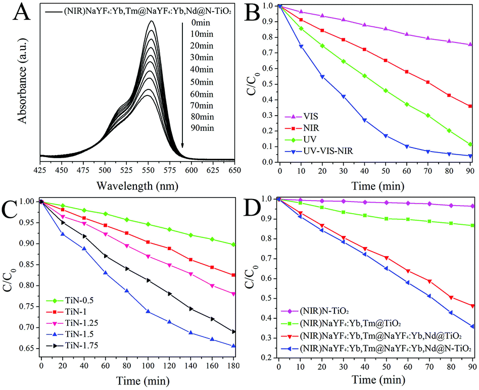
3.5 Photocatalytic activities of the prepared samples
The photocatalytic activities of the prepared Tm/Yb@Yb/Nd@N-TiO2 NPs (1.38 at% for N/TiO2) were evaluated for different irradiation bands of a Xe lamp. Using the NIR band (780–2500 nm), the sample can effectively decolorize a RhB solution along with increasing irradiation time, showing that this photocatalyst can be directly driven by NIR light (Fig. 6A). Considering that the Tm/Yb@Yb/Nd NCs did not show any photocatalytic activity, this NIR-driven activity should result from the synergetic effects of the UCNs and the N-TiO2 shell. Specifically, the Tm/Yb@Yb/Nd NCs serve as a light converter while the N-TiO2 shell acts as the catalytic site. To confirm this hypothesis, the activity of the sample was also individually assessed under irradiation with the UV band and Vis band, respectively (Fig. 6B). As expected, the sample shows a high activity under UV irradiation (300–420 nm), owing to the existence of a well-crystalline TiO2 shell. For the Vis band (420–780 nm), notable activity was also observed due to the fact that elemental N has been doped into the TiO2, which can extend its absorption to the Vis region (Fig. S4†). Through adjusting the doping amount of the N element, the activity of the sample using the Vis band can also be tuned (Fig. 6C). The optimal N-doping for achieving the best Vis activity is displayed by the TiN-1.5 sample, in which the actual N doping content is around 1.38 at%, (see Table S1†). Using the full Xe spectrum (300–2500 nm), the Tm/Yb@Yb/Nd@N-TiO2 displays a very fast degradation speed for the RhB molecules (see blue line in Fig. 6B), showing synergetic contributions from the UV, Vis and NIR bands.
 |
| | Fig. 6 Photocatalytic activities of the Tm/Yb@Yb/Nd@N-TiO2 NPs: (A) using NIR band irradiation; (B) comparison of the activities using different irradiation bands; (C) samples with different N-doping amounts under Vis band irradiation; (D) comparison of different control samples under NIR band irradiation. | |
To clarify the contribution of the different components in the hybrid photocatalyst, several control samples were also synthesized and their activities were evaluated using the NIR band (Fig. 6D). Without a NaYF4:Yb,Nd shell, the activity of the NaYF4:Yb,Tm@TiO2 NPs is relatively low because they can only harness the NIR light around the 980 nm band. In comparison, epitaxial growth of a NaYF4:Yb,Nd shell on the NCs will greatly enhance their NIR activity. Such an enhancing effect of the shell can be understood from three aspects: (1) addition of one more NIR absorption band at 808 nm; (2) further improvement of the 980 nm absorption due to the codoping of Yb3+ in the shell;38,39 (3) boosting the UC emissions of the NaYF4:Yb,Tm NCs through amending their surface defects (see Fig. 5).36 On the other hand, N doping in the N-TiO2 shell can further enhance the sample activity compared to the sample with a pure TiO2 shell. This is because the N-TiO2 shell can absorb both UV and Vis emissions from the core UCNs. We also investigated the photocatalytic activities of the sample using a commercial NIR laser, 808 nm and 980 nm, respectively (Fig. S5†). The results also show that the synergetic effects of the UCN cores and N-TiO2 are important to their NIR-driven activity. The degradation speed of RhB under different NIR lasers is comparable using the same power density (ca. 50 mW cm−2).
3.6 Effect of the core–shell configuration of UCNs on the activities of the samples
The core–shell configuration of the Tm/Yb@Yb/Nd NCs also has an important effect on the photocatalytic activity of the final samples. Using a similar preparation method, we have also synthesized Yb3+/Tm3+/Nd3+ triple-doped NaYF4 NCs and core–shell NaYF4: Yb,Nd@NaYF4:Yb,Tm NCs (Nd/Yb@Yb/Tm) with a reverse doping manner. From the TEM images (Fig. 7A and B), one can see that both samples also have a high quality size and shape. However, the intensities of the UC emissions for these samples are obviously varied using an excitation wavelength of either 808 nm or 980 nm (Fig. 7C and S6†). Accordingly, these samples after N-TiO2 coating display different activities, showing a positive correlation with their UC emissions. It is known that codoping of sufficient amounts of Nd3+ and Tm3+ together will lead to back energy-transfer from Tm3+ to Nd3+, which is greatly detrimental to their total UC emissions.26,27 As such, spatial separation of Tm3+ and Nd3+ in the core and shell is a better choice to suppress the back energy-transfer.40 From the viewpoint of surface defects, the doping activator ions (Tm3+) into the core is preferred because surface defects around Tm3+ ions can be amended by the homogeneous shell. At the same time, Nd3+ ions doped into the outer layer absorb the incident NIR light around 808 nm easier than those doped into the core. Therefore, the UC intensities of the samples follow a sequence of Tm/Yb@Yb/Nd > Nd/Yb@Yb/Tm > NaYF4:Yb,Tm,Nd, which would direct their photocatalytic performance after N-TiO2 coating.
 |
| | Fig. 7 TEM images of the (A) NaYF4:Yb,Nd,Tm NCs and (B) Nd/Yb@Yb/Tm NCs; (C) UC spectra and (D) activities of the control samples under the NIR light of a Xe lamp. | |
3.7 Working mechanism for the hybrid photocatalyst
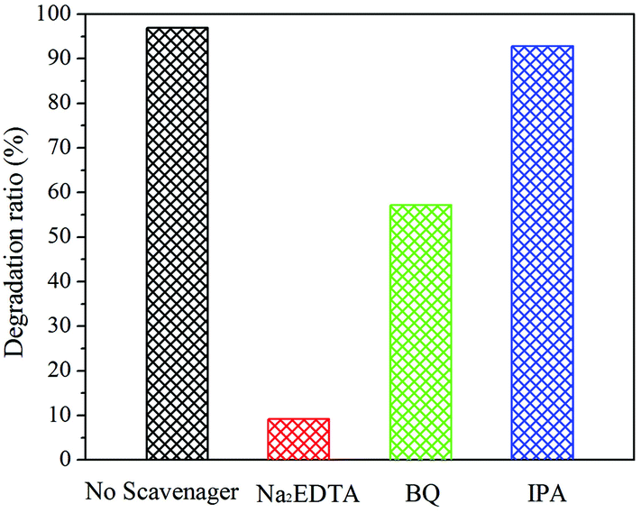
To investigate the main reactive species generated in the present photocatalytic system, different scavengers were employed to suppress the sample activity. Specifically, isopropanol (IPA), ethylenediaminetetraacetic acid disodium salt (Na2EDTA) and benzoquinone (BQ) were used to detect hydroxyl radicals (˙OH), photogenerated holes (h+) and superoxide radicals (˙O2−), respectively.41 With the introduction of IPA, only a slight decrease in the activity was observed, showing that ˙OH are not the main reactive species. In contrast, the sample activity was significantly restrained when Na2EDTA was used as the scavenger, revealing that h+ are the main reactive species for RhB degradation in this system. At the same time, the sample activity was also restrained to some extent when BQ was added into the system (see Fig. 8). This result implies that a few ˙O2− radicals were also generated as a minor reactive species.
 |
| | Fig. 8 Comparison of the sample activity in the presence of different scavengers for identifying the ROS species. | |
Based on the above information, a working mechanism for the Tm/Yb@Yb/Nd@N-TiO2 NPs is illustrated in Scheme 2. Under NIR irradiation, the Tm/Yb@Yb/Nd NCs emit strong upconverted UV and Vis emissions. Then, both the UV and Vis emissions are rapidly absorbed by the surface-coating N-TiO2 shell and lead to the production of photogenerated e− and h+. The h+ have a strong oxidizing capability to directly decolorize the RhB solution. At the same time, the photogenerated e− can capture O2 molecules and produce ˙O2− radicals, serving as a minor reactive species in the system. As such, the Tm/Yb@Yb/Nd@N-TiO2 NPs can be directly activated under NIR light. Note that the N-TiO2 shell itself can also be directly activated by UV or Vis light from the light source (e.g., Xe lamp or sunlight). Therefore, this hybrid nanostructure is able to serve as a UV/Vis/NIR photocatalyst using the full solar spectrum.
 |
| | Scheme 2 Schematic illustration of the working mechanism for the hybrid core–shell–shell photocatalyst. | |
4. Conclusions
In summary, we have synthesized Tm/Yb@Yb/Nd@N-TiO2 hybrid photocatalysts with a core–shell–shell structure. The prepared nanocomposites were characterized using TEM, XRD, EDX, XPS and PL, and their photocatalytic activities have been evaluated. In the developed photocatalysts, the UCN cores are dually sensitized and thus can simultaneously utilize two NIR bands (980 nm and 808 nm), and the N-TiO2 shell can fully absorb the four upconverted UV and Vis emissions. In comparison with conventional Tm/Yb@TiO2 NPs, these nanocomposites show a significantly enhanced NIR-driven activity. The effects of the doping manner in the UCNs and the N-doping level in the shell have also systematically investigated. A working mechanism for such hybrid photocatalysts was also proposed. It is expected that the developed nanocomposites will offer promising applications in the fields of photocatalytic dye degradation, water splitting, DSSC, and photodynamic therapy.
Acknowledgements
The authors acknowledge financial support from the National Nature Science Foundation of China (no. 21273203 and 21374105) and Zhejiang Provincial Natural Science Foundation (no. R15B010001, R12B040001 and Q16B010001).
Notes and references
- A. Fujishima and K. Honda, Nature, 1972, 238, 37–38 CrossRef CAS PubMed.
- D. Yan and L. K. Pan, Inorg. Chem. Front., 2016, 3, 464–468 RSC.
- X. Chen and S. S. Mao, Chem. Rev., 2007, 107, 2891–2959 CrossRef CAS PubMed.
- A. L. Linsebigler, G. Lu and J. T. Yates, Chem. Rev., 1995, 95, 735–758 CrossRef CAS.
- Y. F. Sun, J. B. Zhu, L. F. Bai, Q. Y. Li, X. Zhang, W. Tong and Y. Xie, Inorg. Chem. Front., 2014, 1, 58–64 RSC.
- J. G. Yu, J. X. Low, W. Xiao, P. Zhou and M. Jaroniec, J. Am. Chem. Soc., 2014, 136, 8839–8842 CrossRef CAS PubMed.
- R. Li, S. K. Wu, X. Y. Wan, H. X. Xu and Y. J. Xiong, Inorg. Chem. Front., 2016, 3, 104–110 RSC.
- R. Asahi, Y. Taga, W. Mannstadt and A. J. Freeman, Phys. Rev. B: Condens. Matter, 2000, 61, 7459–7465 CrossRef CAS.
- D. Mitoraj and H. Kisch, Angew. Chem., Int. Ed., 2008, 47, 9975–9978 CrossRef CAS PubMed.
- R. Asahi, T. Morikawa, H. Irie and T. Ohwaki, Chem. Rev., 2014, 114, 9824–9852 CrossRef CAS PubMed.
- S. Bai, J. Jiang, Q. Zhang and Y. J. Xiong, Chem. Soc. Rev., 2015, 44, 2893–2939 RSC.
- K. Zhao, S. L. Zhao, J. Qi, H. J. Yin, C. Gao, A. M. Khattak, Y. J. Wu, A. Iqbal, L. Wu, Y. Gao, R. B. Yu and Z. Y. Tang, Inorg. Chem. Front., 2016, 3, 488–493 RSC.
- Z. Y. Hou, Y. X. Zhang, K. R. Deng, Y. Y. Chen, X. J. Li, X. R. Deng, Z. Y. Cheng, H. Z. Lian, C. X. Li and J. Lin, ACS Nano, 2013, 9, 2584–2599 CrossRef PubMed.
- W. F. Yang, X. Y. Li, D. Z. Chi, H. J. Zhang and X. G. Liu, Nanotechnology, 2014, 25, 482001 CrossRef PubMed.
- Q. C. Xu, Y. Zhang, M. J. Tan, Y. Liu, S. J. Yuan, C. Choong, N. S. Tan and T. T. Y. Tan, Adv. Healthcare Mater., 2012, 1, 470–474 CrossRef CAS PubMed.
- Z. Q. Li, C. L. Li, Y. Y. Mei, L. M. Wang, G. H. Du and Y. J. Xiong, Nanoscale, 2013, 5, 3030–3036 RSC.
- S. Q. Huang, L. Gu, C. Miao, Z. Y. Lou, N. W. Zhu, H. P. Yuan and A. D. Shan, J. Mater. Chem. A, 2013, 1, 7874–7879 CAS.
- G. B. Shan and G. P. Demopoulos, Adv. Mater., 2010, 22, 4373–4377 CrossRef CAS PubMed.
- S. Heer, K. Kömpe, H. U. Güdel and M. Haase, Adv. Mater., 2004, 16, 23–24 CrossRef.
- M. Haase and H. Schäfer, Angew. Chem., Int. Ed., 2011, 50, 5808–5829 CrossRef CAS PubMed.
- Y. N. Tang, W. H. Di, X. S. Zhai, R. Y. Yang and W. P. Qin, ACS Catal., 2013, 3, 405–412 CrossRef CAS.
- W. Wang, W. J. Huang, Y. R. Ni, C. H. Lu and Z. Z. Xu, ACS Appl. Mater. Interfaces, 2014, 6, 340–348 CAS.
- Y. W. Zhang and Z. L. Hong, Nanoscale, 2013, 5, 8930–8933 RSC.
- L. L. Liang, Y. M. Liu, C. H. Bu, K. M. Guo, W. W. Sun, N. Huang, T. Peng, B. Sebo, M. M. Pan, W. Liu, S. S. Guo and X. Z. Zhao, Adv. Mater., 2013, 25, 2174–2180 CrossRef CAS PubMed.
- W. K. Su, M. M. Zheng, L. Li, K. Wang, R. Qiao, Y. Zhong, Y. Hu and Z. Q. Li, J. Mater. Chem. A, 2014, 2, 13486–13491 CAS.
- Y. F. Wang, G. Y. Liu, L. D. Sun, J. W. Xiao, J. C. Zhou and C. H. Yan, ACS Nano, 2013, 7, 7200–7206 CrossRef CAS PubMed.
- X. J. Xie, N. Y. Gao, R. R. Deng, Q. Sun, Q. H. Xu and X. G. Liu, J. Am. Chem. Soc., 2013, 135, 12608–12611 CrossRef CAS PubMed.
- H. L. Wen, H. Zhu, X. Chen, T. F. Hung, B. L. Wang, G. Y. Zhu, S. F. Yu and F. Wang, Angew. Chem., Int. Ed., 2013, 52, 13419–13423 CrossRef CAS PubMed.
- Z. Q. Li, Y. Zhang and S. Jiang, Adv. Mater., 2008, 20, 4765–4769 CrossRef CAS.
- H. Guo, Z. Q. Li, H. S. Qian, Y. Hu and I. N. Muhammad, Nanotechnology, 2010, 21, 125602 CrossRef PubMed.
- T. Rinkel, A. N. Raj, S. Dühnen and M. Haase, Angew. Chem., Int. Ed., 2016, 55, 1164–1167 CrossRef CAS PubMed.
- S. Wilhelm, M. Kaiser, C. Würth, J. Heiland, C. C. Carrion, V. Muhr, O. S. Wolfbeis, W. J. Parak, U. R. Genger and T. Hirsch, Nanoscale, 2015, 7, 1403–1410 RSC.
- K. A. Abel, J. C. Boyer and F. C. J. M. van Veggel, J. Am. Chem. Soc., 2009, 131, 14644–14645 CrossRef CAS PubMed.
- C. Liu, T. Sun, L. Wu, J. Y. Liang, Q. J. Huang, J. Chen and W. H. Hou, Appl. Catal. B, 2015, 170, 17–24 CrossRef.
- J. Wang, D. N. Tafen, J. P. Lewis, Z. L. Hong, A. Manivannan, M. J. Zhi, M. Li and N. Q. Wu, J. Am. Chem. Soc., 2009, 131, 12290–12297 CrossRef CAS PubMed.
- L. D. Sun, Y. F. Wang and C. H. Yan, Acc. Chem. Res., 2014, 47, 1001–1009 CrossRef CAS PubMed.
- G. Y. Chen, T. Y. Ohulchanskyy, S. Liu, W. C. Law, F. Wu, M. T. Swihart, H. Agren and P. N. Prasad, ACS Nano, 2012, 6, 2969–2977 CrossRef CAS PubMed.
- F. Vetrone, R. Naccache, V. Mahalingm, C. G. Morgan and J. A. Capobianco, Adv. Funct. Mater., 2009, 19, 2924–2929 CrossRef CAS.
- K. Wang, W. L. Qincheng, Y. Zhang, R. Qiao, S. Li and Z. Q. Li, RSC Adv., 2015, 5, 62899–62904 RSC.
- J. Shen, G. Y. Chen, A. M. Vu, W. Fan, O. S. Bilsel, C. C. Chang and G. Han, Adv. Opt. Mater., 2013, 1, 644–650 CrossRef.
- L. Wang, Y. Y. Chai, J. Ren, J. Ding, Q. Q. Liu and W. L. Dai, Dalton Trans., 2015, 44, 14625–14634 RSC.
Footnote |
| † Electronic supplementary information (ESI) available. See DOI: 10.1039/c6qi00194g |
|
| This journal is © the Partner Organisations 2016 |
Click here to see how this site uses Cookies. View our privacy policy here.