
Rational design of semiconductor-based photocatalysts for advanced photocatalytic hydrogen production: the case of cadmium chalcogenides
You
Xu
a,
Yi
Huang
ab and
Bin
Zhang
*ab
aDepartment of Chemistry, School of Science, Tianjin University, Tianjin 300072, China. E-mail: bzhang@tju.edu.cn
bCollaborative Innovation Center of Chemical Science and Engineering (Tianjin), Tianjin 300072, China
First published on 2nd February 2016
Abstract
Semiconductor-based photocatalytic hydrogen (H2) production from water has recently received considerable attention because of its enormous potential for solving worldwide ever-increasing energy crises and environmental issues. Among various semiconductors, cadmium chalcogenides (CdX, X = S, Se, Te), with a variety of superior properties including appropriate bandgaps for visible-light absorption, proper conduction band edge potentials for water reduction and abundant reserves on the earth, have fuelled great interest in exploring their photocatalytic properties for solar-driven H2 production from water. This review article summarizes the recent progress in developing CdX-based photocatalyst systems for the production of H2 from solar water splitting. The basic mechanistic fundamentals of CdX photocatalysts and various strategies to enhance the activity and stability of this class of photocatalysts are introduced in detail. Finally, some key scientific issues and prospective directions in this area of research are also discussed.
 Bin Zhang | Bin Zhang received his PhD degree from the University of Science and Technology of China in 2007. He carried out postdoctoral research at the University of Pennsylvania (July 2007–July 2008) and worked as an Alexander von Humboldt fellow at the Max Planck Institute of Colloids and Interfaces (August 2008–July 2009). Currently, he is a professor in the chemistry department at Tianjin University and the Collaborative Innovation Center of Chemical Science and Engineering (Tianjin). He mainly focuses on the development of chemical transformation strategies to prepare porous and ultrathin nanomaterials and their hybrids for energy catalytic applications. |
1. Introduction
Rising global energy demands, rapidly diminishing reservoirs of traditional fossil fuels and ever-increasing environmental concerns have motivated the significant requirements for clean and renewable energy sources.1–5 Hydrogen (H2), with its relative abundance of sources of generation, high density of energy (122 kJ g−1) and environmental friendliness, is regarded as an attractive and alternative energy carrier without CO2 emissions.6–8 Currently, H2 used in industry is mainly obtained from non-renewable fossil sources by means of steam reforming or coal gasification processes. However, the production processes based on these pathways are usually complex, expensive, environmentally hazardous and unsustainable, not to mention the generation of greenhouse gases (CO2) as a by-product. Recently, splitting water for H2 production using solar energy has received much attention due to the fact that it can convert sustainable solar energy into storable renewable chemical fuel (H2), which provides a promising solution to the worldwide ever-increasing energy crises and environmental issues. Approaches for solar water splitting mainly include thermochemical water splitting, photobiological water splitting, photochemical or photocatalytic water splitting and photoelectrochemical or photoelectrocatalytic water splitting. Among these approaches, photochemical water reduction for H2 production using semiconductor-based photocatalyst systems, which can utilize solar energy to drive a thermodynamic uphill reaction to generate molecular H2, is the focus of considerable attention.Since the pioneering discovery of photoelectrochemical water splitting on a TiO2 photoanode by Honda and Fujishima in 1972,9 the technology of semiconductor-based photocatalytic water splitting has undergone considerable development and numerous active semiconductor-based photocatalyst systems have been explored in this important field. In general, the photocatalytic materials for water splitting are required to perform at least two fundamental functions: light harvesting of the maximal possible part of the solar energy spectrum and a catalytic function of efficient water decomposition into O2 and H2. Thus, to efficiently utilize solar energy for photocatalytic H2 production from water, an ideal semiconductor material should meet at least three requirements: an appropriate bandgap for solar energy absorption, proper conduction band position for water reduction, and good stability under the required reaction conditions.
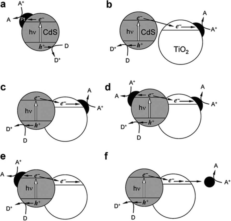
Generally, H2 and/or O2 generation from water using solar energy and semiconductor materials can be achieved by means of two different kinds of systems: photoelectrochemical water splitting systems (including single-photoelectrode and dual-photoelectrode systems) and photocatalytic water splitting systems (including half-reaction and overall water splitting systems). In brief, the basic principle of photoelectrochemical water splitting is based on the conversion of solar energy into electricity, which is then used for water electrolysis, within a photoelectrochemical cell involving two electrodes immersed in an electrolyte solution. In this case, at least one electrode is made of a semiconductor which is able to efficiently absorb the sunlight and generate photoexcited charge carriers. There are three options for the arrangement of photoelectrodes in the assembly of photoelectrochemical cells for the water splitting reaction: (i) an n-type semiconductor as the photoanode and a metal counter electrode (usually Pt); (ii) a p-type semiconductor as the photocathode and a metal counter electrode (usually Pt); (iii) an n-type semiconductor as the photoanode and a p-type semiconductor as the photocathode. In photoanodes made of n-type semiconductors, photogenerated holes accumulate on the surface of the n-type semiconductor and can be used to oxidize water to generate O2 (if its valance band edge is more positive than the O2 evolution potential), while electrons are transferred to the counter electrode via the back contact and an external circuit, and used for the H2 evolution reaction (case i). On the other hand, photocathodes made of p-type semiconductors can utilize photogenerated electrons for H2 evolution when their conduction band edge is more negative than the H2 evolution potential; simultaneously, the holes are transferred over the external circuit to the counter electrode for O2 evolution (case ii). Alternatively, a photoanode and a photocathode can be connected in tandem to generate a dual-photoelectrode system (case iii). With the help of the external electric field, which facilitates the charge carrier separation and greatly reduces the recombination possibility of charge carriers, photoelectrochemical systems usually exhibit relatively high efficiency for water splitting.
Compared to photoelectrochemical systems, the main advantages of photocatalytic water splitting systems are their simple operation and low cost. Photocatalytic water splitting systems can be divided into two types: single photocatalyst systems and Z-scheme systems. A semiconductor material can work as a photocatalyst for photocatalytic H2 and/or O2 production from water if it meets all the requirements (e.g. band gap, band edge positions). Note that a single photocatalyst overall water splitting system under visible light is one of the greatest challenges in the field of water splitting. In most cases, water reduction or oxidation half-reactions are studied in this type of system in the presence of appropriate sacrificial reagents for H2 or O2 generation. Alternatively, two semiconductors can be connected (in series with reversible redox shuttles in some cases) to construct Z-scheme systems, which can achieve overall water splitting.
Concerning the mechanisms of the reactions, the principle of photocatalytic water splitting is similar to that of photoelectrochemical water splitting. The essential difference between the two consists of the location of the sites of the surface reactions. In the photoelectrochemical process, H2- and O2-evolution reactions take place at two spatially separated electrodes. In the photocatalytic process, both oxidation and reduction occur on the surface of the photocatalyst, which exhibits the functions of both anode and cathode. The practical difference between photocatalytic and photoelectrochemical water splitting is that the latter results in both O2 and H2 evolving separately, while in the former, a mixture of both gases is evolved. Moreover, as the photoelectrochemical reactions on photoelectrodes are driven by photoexcited minority carriers, the material selection for constructing the photoanode and photocathode is limited not only by their band gap and band edge positions but also their intrinsic conductivity characteristics (n-type or p-type). Differing from the photoelectrochemical water splitting process, both n-type and p-type semiconductors can work as photocatalysts for photocatalytic water splitting when their band gap and band edge positions meet the requirements. This review is focused on the development of photocatalytic systems for H2 generation.
Among the various promising systems under investigation, cadmium chalcogenides (CdX, X = S, Se, Te) are regarded as good candidates for photocatalytic H2 production because of their following superior characteristics:10–12 (1) CdX are visible-light-responsive semiconductors, which enables them to absorb solar energy across a broader spectrum than UV-absorbing semiconductors; (2) CdX nanocrystals possess excellent light-harvesting characteristics, with molar absorptivities of about 105–107 M−1 cm−1; (3) their bandgaps, redox potentials and absorption spectra, which largely determine their photocatalytic properties, can be tuned by controlling a series of structural parameters such as composition, size, shape and morphology; (4) they can be surface-functionalized with a rich variety of ligands, which not only enable them to possess either hydrophilic or hydrophobic properties, but also provides selectivity of functional groups for interaction with other materials. One can see that CdX materials, which have been extensively studied for photocatalytic H2 generation and which we extensively refer to in this article, are indeed potential abundant and useful water splitting materials, even though there are environmental and toxicity concerns about potentially harmful release of cadmium.
During the past four decades, significant interest and considerable efforts have been directed to the development of CdX-based materials as photocatalysts for visible-light-driven H2 generation due to their unique physical, chemical and optical properties. To date, numerous successful achievements have demonstrated their significant applications in photocatalytic H2 production, while recent great progress in materials science and nanotechnology has also greatly accelerated the evolution of this field. Up till now, many excellent earlier and recent review articles have been published by several research groups to summarize the achievements and advances in the field of semiconductor-based photocatalytic water splitting.13–27 However, there is no one review focusing on CdX-based photocatalysis for H2 production. Therefore, a timely review to systematically summarize the related progress and advances in CdX-based photocatalytic H2-evolution systems is highly desirable. In this review article, we will first describe the basic mechanistic fundamentals of CdX-based photocatalysts. We will then discuss the various approaches to improve the photocatalytic performance of various kinds of CdX-based photocatalysts. The synthetic procedures, structural features and photoactivity enhancement mechanism are discussed based on some representative and important examples. In particular, the focus will be on the relationship between the structural characteristics and features of photocatalysts and their photocatalytic performance. Finally, some key scientific issues as well as prospective directions are also discussed.
2. The mechanistic fundamentals of CdX-based photocatalysts
Semiconductor-based photocatalysis is defined as the chemical reaction induced by photoirradiation in the presence of one or more semiconductors as the catalysts, or more specifically, the photocatalysts. Basically, as illustrated in Fig. 1a, semiconductor-based photocatalysis for the splitting of water into H2 and O2 involves the following three major steps: (i) absorption of solar energy by the semiconductor and generation of mobile charge carriers; (ii) photogenerated charge separation and diffusion from the photogenerated center to the semiconductor's surface; (iii) charge utilization for water reduction or oxidation on the photocatalyst surface. The first two steps (i and ii) relate to the photon absorption and charge carrier transfer in the semiconductor, which are analogous to the photovoltaic process, and the last step (iii) is carrier-induced surface reactions. In a semiconductor-based photocatalysis process, the intrinsic properties of the semiconductor materials fundamentally determine the overall efficiency of the photocatalytic reaction.13 Generally, the light-absorbing capability of semiconductor materials largely depends on their band gap. Semiconductors with a wider band gap can only utilize the parts of the solar energy spectrum in the UV or near UV regions, while those with a narrower band gap can respond to visible light. From the perspective of solar energy utilization, those visible-light-responding semiconductor materials are more promising photocatalysts as they can utilize solar energy more efficiently. Theoretically, the minimum band gap of semiconductor materials for the water splitting reaction appears to be 1.23 eV according to the redox potential of H+/H2 and O2/H2O redox pairs. In addition to this minimum thermodynamic requirement, the additional kinetic overpotential associated with the electron transfer processes and gas evolution step due to energy losses should be taken into account.28 Therefore, a much larger band gap (usually >2.0 eV) of the semiconductor is often required for practical photocatalytic systems. Besides the band gap, the positions of the valence band (VB) and conduction band (CB) of a semiconductor, which determine the reduction and oxidation power of photogenerated carriers, are also important for the process of photocatalytic water splitting. Specifically, for H2 production from photocataltic water-splitting, the bottom of the CB should be higher (more negative) than the hydrogen evolution potential (+0 V vs. normal hydrogen electrode at pH 0), while the top of the VB should be lower (more positive) than the water oxidation potential (+1.23 V vs. normal hydrogen electrode at pH 0) for water-splitting O2 production.13,16 Among the CdX semiconductors, CdS and CdSe are n-type semiconductors with direct bandgaps of ∼2.5 and ∼1.7 eV, respectively, while CdTe is a p-type semiconductor with a direct bandgap energy of ∼1.4 eV (Fig. 1b). From a thermodynamics perspective, CdX semiconductors are promising candidates for photocatalytic water reduction because they possess more negative CB potentials compared to the reduction potential of water. In addition, their electronic band structure and the positions of the CB and VB can be finely tuned by modifying their crystal structure, composition and morphology.29 Numerous research results have demonstrated that precise engineering of a material’s composition and structure can lead to improved light-harvesting efficiency or/and enhanced reduction/oxidation abilities of the photogenerated carriers, which finally results in an improved photocatalytic activity.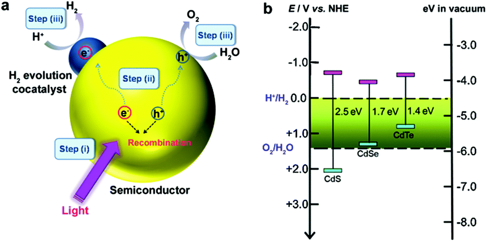 | ||
| Fig. 1 (a) Illustration of the main processes in semiconductor-based photocatalytic water splitting for H2 and O2 evolution. (b) Relationship between band structure of CdS, CdSe and CdTe semiconductors and redox potentials of water splitting (pH = 0). | ||
After excited charges are generated upon light absorption by a semiconductor, efficient charge separation and fast charge transport are fundamentally important for semiconductor-based photocatalysis. During step (ii), the recombination of the photogenerated charge carriers inside the CdX photocatalyst competes with the charge separation/migration process, which greatly affects the overall efficiency of the photocatalytic reaction. Charge recombination in step (ii) can occur via different mechanisms, including radiative and nonradiative recombinatiom.15 It is well recognized that the crystal structure, crystallinity, and particle size of semiconductor materials strongly affect step (ii). Currently, considerable efforts have been made to increase the separation efficiency and to reduce the recombination probability of photoexcited charge carriers in CdX-based photocatalysts. One popular strategy is structure and morphology control, that is, to develop novel CdX-based photocatalysts with controlled structures and morphologies. Another promising option is to integrate the CdX with other materials to form heterogeneous photocatalysts. When carefully designed, some photocatalytic behaviours, including the direction of mobility, the diffusion distance, and the recombination rate of photogenerated charge carriers in these CdX-based heterogeneous photocatalyst systems comprising two or more materials or phases can be well-controlled. Beside these two strategies, another alternative strategy for the extraction of photogenerated electrons from the CdX semiconductor to reduce the recombination probability of photogenerated carriers is the hybridization of CdX with carbon-based materials (such as carbon nanotubes or graphene). Taking the advantages of carbon-based materials, this kind of CdX-based composite can exhibit improved photoactivity.
It should be emphasized that, even if the separated photogenerated charge carriers possess thermodynamically sufficient potential for H2- and O2-evolution reactions, they may recombine if there are no suitable active/reaction sites available on the photocatalyst surface. Therefore, the surface chemical reactions in step (iii), which are driven by photogenerated carriers, are crucial for achieving high efficiency in charge utilization. Water molecules in contact with the semiconductor surface can be reduced to form H2 by photoelectrons from the CB and oxidized to form O2 by photoholes from the VB, if the energetic positioning of the bands matches the redox potentials of water reduction and oxidation. It is well recognized that loading appropriate cocatalysts on the surface of photocatalysts can promote or accelerate the surface chemical reactions.17,18,30 On one hand, cocatalysts can serve as the active reaction sites where H2- or O2-evolution reactions occur. On the other hand, cocatalysts can facilitate the charge separation and reduce the overpotential and activation energy of H2- or O2-evolution reactions. Additionally, cocatalysts can enhance the photostability of semiconductor photocatalysts. So far, many kinds of materials, including metals, inorganic compounds, hydrogenases and molecular complexes, have been employed as cocatalysts to promote or accelerate the surface redox reactions of CdX-based photocatalysts. Some of them display high efficiency and good robustness to significantly enhance the photocatalytic H2 evolution activity of CdX-based photocatalyst systems.
Apart from the above mentioned aspects, photocorrosion, which results from hole-driven oxidation reactions, is another important issue for CdX-based photocatalysts. Taking CdS as an example, S2− in the CdS rather than a water molecule is oxidized by photogenerated holes, accompanied with elution of Cd2+ ions in aqueous media when exposed long-term to visible light,12,16,31 according to eqn (1). Photocorrosion is a critical drawback of CdX photocatalysts, which seriously limits their practical applications in photocatalysis. Sacrificial electron donors are often needed to consume the photongenerated holes or provide electrons for proton reduction when using CdX semiconductors for photocatalytic H2 production from water. Frequently used hole scavenger materials in CdX-based photocatalytic H2-evolution systems include lactic acid, a mixture of sulphide and sulphite, ascorbic acid, tertiary amines, triethanolamine and alcohols.
| CdS + 2h+ → Cd2+ + S | (1) |
Taking these mechanistic fundamentals into account, an efficient and stable photocatalyst system based on CdX semiconductors should achieve high efficiency in visible-light harvesting, facilitate the photogenerated charge carrier separation and transfer and effectively prevent charge recombination, whilst efficiently suppressing photocorrosion, and possess good photostability. Synthetic advancement makes it possible to design and synthesize the desired nanostructures and nanomaterials with a particular band alignment favouring an expected charge separation. During the last decades, extensive efforts have been made to enhance the photocatalytic activity and stability of CdX semiconductors. The important and representative strategies will be discussed in detail in the following section based on some selected examples.
3. Strategies for enhancing the photocatalytic performance of CdX
3.1 Modifying the crystal structure and morphology of CdX
Bulk CdX materials alone demonstrate low photoactivity and poor stability for H2 photogeneration, mainly due to the rapid surface/bulk recombination of photogenerated electrons and holes and large H2 production activation energy or overpotential. Compared to their bulk counterparts, CdX materials on the nanoscale show more potential for photocatalytic applications owing to their unique properties and advantages. Firstly, the decrease in particle size can usually directly result in an increase in the surface area and active reaction sites, both of which are important for surface chemical reactions. Secondly, reducing the particle size of a photocatalyst can shorten the diffusion pathway of the photogenerated charge carriers, leading to decreased recombination probability. Thirdly, making semiconductor materials in the form of nanoparticles allows us to utilize the quantum confinement effect for both opening their bandgap and for adjustment of their energy levels. Furthermore, investigations have revealed that the separation and migration of photogenerated charge carriers are strongly affected by the crystal and structural features of the materials (e.g. crystallinity) and a series of surface properties including particle size, surface area, surface structure, active reaction sites, etc.13 By tuning these parameters, the properties of a semiconductor material such as the bandgap and the CB and VB positions can, in principle, be tailored to enhance its activity and stability in photocatalytic H2 production applications.32–42![[1 with combining macron]](https://www.rsc.org/images/entities/char_0031_0304.gif) 1} facets (r1′) of CdS nanocrystals was achieved by simply employing a syringe pump, which enables fine tuning of the crystal shape from nanocones, to nanofrustums, and further to nanoplates (Fig. 2a). Study of their photocatalytic activities revealed that the CdS nanoplates, with the largest {0001} facets, exhibited the highest photocatalytic activity for H2 production in comparison to the nanocones and nanofrustums (Fig. 2b).
1} facets (r1′) of CdS nanocrystals was achieved by simply employing a syringe pump, which enables fine tuning of the crystal shape from nanocones, to nanofrustums, and further to nanoplates (Fig. 2a). Study of their photocatalytic activities revealed that the CdS nanoplates, with the largest {0001} facets, exhibited the highest photocatalytic activity for H2 production in comparison to the nanocones and nanofrustums (Fig. 2b).
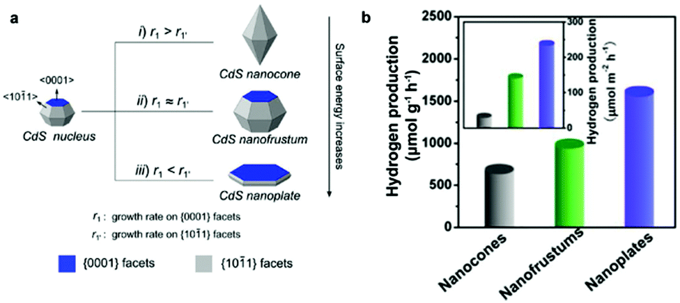 | ||
| Fig. 2 (a) Schematic illustration of the formation of a CdS nanocone, a CdS nanofrustum, and a CdS nanoplate, simply controlled by adjusting Cd2+ injection rate. (b) Average photocatalytic H2 production rate of the various CdS nanostructures. Inset in (b) shows corresponding specific activities that were normalized with respect to their calculated surface areas. Reproduced with permission from ref. 34. Copyright 2015 American Chemical Society. | ||
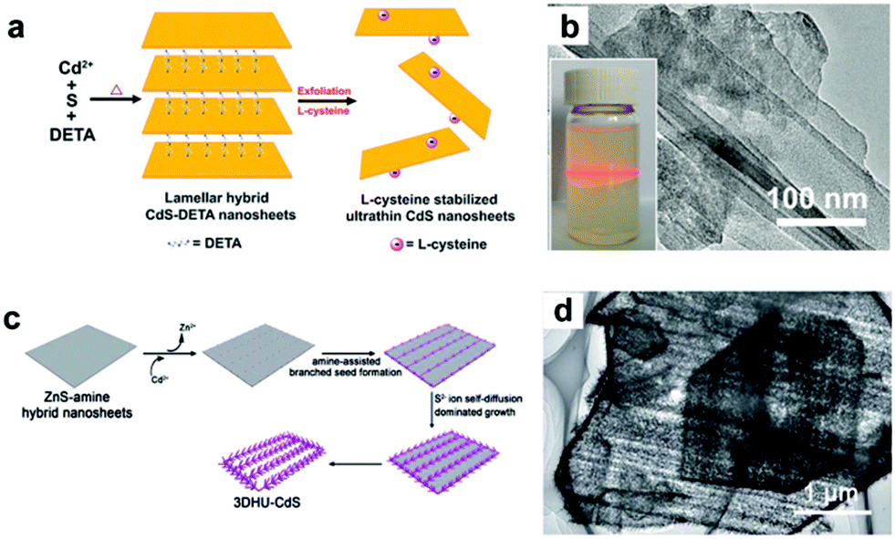 | ||
| Fig. 3 (a) Schematic illustration of the preparation of L-cysteine-stabilized ultrathin CdS nanosheets. (b) TEM image of ultrathin CdS nanosheet and the corresponding colloidal CdS dispersion displaying the Tyndall effect. (c) Schematic illustration of the preparation of 3D hierarchical ultrathin-branched CdS nanowire arrays. (d) TEM image of the 3D hierarchical ultrathin-branched CdS nanowire arrays. (a, b) Reproduced with permission from ref. 37. Copyright 2013, The Royal Society of Chemistry. (c, d) Reproduced with permission from ref. 38. Copyright 2015, The Royal Society of Chemistry. | ||
Several research groups have investigated the size-dependent performance of CdX materials in the photocatalytic H2 evolution. The work by Sathish et al. showed that CdS particles on the nanometer scale could display a higher photocatalytic activity for H2 generation compared to bulk CdS counterparts.40 In a recent example, Osterloh and co-workers provided the first quantitative analysis of quantum-size-controlled photocatalytic H2 evolution at semiconductor (CdSe)–solution interfaces.41 Based on their results, it was found that the H2 evolution rate from illuminated suspended CdSe quantum dots (QDs) in aqueous Na2SO3 solution was dependent on the size of the CdSe nanocrystals. The study by Grigioni et al. also demonstrated the size-dependent performance of CdSe QDs in the photocatalytic evolution of H2 under visible light irradiation.42 They found that 2.8 nm-sized CdSe samples exhibited the highest H2 production rate due to their good visible light harvesting capability, suitable conduction band position and low probability of photogenerated charge carrier recombination.
It must be realized that despite numerous evidences demonstrating the feasibility of photocatalytic water splitting using pure CdX semiconductor nanomaterials, their H2 evolution rates and the quantum efficiencies (QEs) are still too low to be able to efficiently utilize solar energy, even in the presence of sacrificial agents. Therefore, many research efforts have been directed to improve their photocatalytic properties by modifying CdX with other materials through a series of approaches to further modify their activity and stability.
3.2 Forming CdX-based solid solutions
Forming a solid solution is an efficient composition-engineering strategy to modify the photocatalytic properties of CdX semiconductor materials. Compared to the pristine CdX materials, solid solutions possess some unique advantages, such as tunable absorption properties in the visible region of the solar spectrum, controllable band structure and better electrical conductivity with the help of inserted metals (M), leading to an enhanced visible-light response and improved photoactivity.The CdxZn1−xS (0 < x < 1) solid solution, formed by combining semiconductor ZnS with a wide bandgap and semiconductor CdS with a narrow bandgap, has attracted much research interest for visible-light-driven photocatalysis applications.43–51 For example, our group have synthesized nanoporous single-crystal-like CdxZn1−xS nanosheets with tunable pore size and composition by the cation-exchange reaction of inorganic–organic hybrid ZnS–DETA nanosheets with Cd2+ ions and demonstrated their high photocatalytic activity for H2 production.43Fig. 4a displays the typical scanning electron microscopy (SEM) image of the porous Cd0.5Zn0.5S nanosheets. We demonstrated that the porous Cd0.5Zn0.5S nanosheets showed a stable H2 production rate of about 0.5 mmol h−1 per 0.3 g catalyst, which is about 2.5 times than that of Cd0.5Zn0.5S nanorods (Fig. 4b). In another example, Guo, Yao and co-workers have synthesized a CdxZn1−xS solid solution with nano-twin structures through a precipitate-hydrothermal method and evaluated their photocatalytic activity for H2 evolution.44 Their study results revealed that such CdxZn1−xS nanocrystal photocatalysts showed a higher photocatalytic H2 production activity compared to the pristine CdS counterpart. Among them, Cd0.5Zn0.5S photocatalysts showed the highest activity with a H2 evolution rate of 1.79 mmol h−1 per 0.1 g catalyst and an apparent QE of 43% at 425 nm.
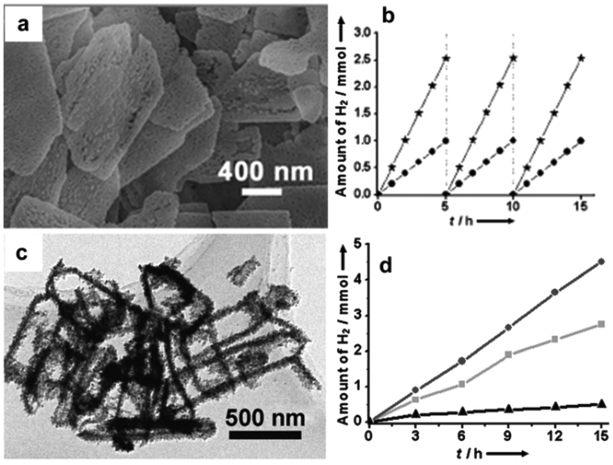 | ||
| Fig. 4 (a) SEM image of porous Cd0.5Zn0.5S nanosheets. (b) Time course of evolved H2 under visible-light irradiation of Cd0.5Zn0.5S porous nanosheets (★) and Cd0.5Zn0.5S nanorods (●). (c) TEM image of hollow Cd0.33Zn0.67Se nanoframes. (d) Time course of evolved H2 under visible-light irradiation of hollow Cd0.33Zn0.67Se nanoframes (●), hollow Cd0.25Zn0.75Se nanoframes (■), and Cd0.33Zn0.67Se nanoparticles (▲). (a, b) Reproduced with permission from ref. 43. Copyright 2012, John Wiley and Sons. (c, d) Reproduced with permission from ref. 56. Copyright 2012, John Wiley and Sons. | ||
Investigations demonstrate that the photocatalytic performance of the CdxZn1−xS solid solution can be further improved by doping with some transition metal ions, such as Cu,45,46 Ni,47 Sn,48 and La.49 For example, Liu et al. have successfully synthesized a Cu doped Cd0.1Zn0.9S photocatalyst by a coprecipitation method, and an apparent QE of about 9.6% can be achieved by the Cd0.1Cu0.01Zn0.89S photocatalyst without any cocatalyst at 420 nm.45 Chen and co-workers reported an efficient strategy for the enhancement of photocatalytic H2 evolution in which La was successfully doped into the depletion layer of the Cd0.6Zn0.4S photocatalyst via a facial solvothermal method.49 Apart from metal doping, non-metal doping is another effective approach to modify the photocatalytic properties of semiconductors. One successful case is doping various nonmetal anions (such as C, N, S, etc.) onto TiO2 to modify its optical and photocatalytic properties,52,53 which should open up interesting possibilities to modify the photocatalytic properties of CdX semiconductors by appropriate nonmetal ion doping.
Except for CdxZn1−xS, other CdX-based solid solutions, such as CdxMn1−xS,54 CdIn2S4,55 and CdxZn1−xSe,56 are also found to possess efficient photocatalytic activity. For example, Ikeue and co-workers have successfully fabricated a CdxMn1−xS photocatalyst through a hydrothermal method.54 They found that the high photocatalytic activity for H2 evolution of this CdxMn1−xS photocatalyst was caused by its low-crystalline character. Moreover, they demonstrated that this CdxMn1−xS photocatalyst showed better tolerance to photocorrosion compared to its pure CdS counterpart. The study by Kale et al. showed efficient photocatalytic H2 production over nanostructured CdIn2S4.55 As an example of the study on CdxZn1−xSe solid solutions, our group synthesized hollow CdxZn1−xSe nanoframes via a selective cation-exchange strategy and demonstrated their composition-dependent photocatalytic activity for H2 production.56Fig. 4c shows the typical TEM image of the hollow Cd0.33Zn0.67Se nanoframes. It was found that the Cd0.33Zn0.67Se nanoframes showed an obviously higher H2 production rate than those of Cd0.25Zn0.75Se nanoframes and Cd0.33Zn0.67Se nanoparticles (see Fig. 4d).
Apart from the component (the choice of inserted metals (M)), the composition (the ratio of M to Cd) of the solid solution can also influence the band energy level and thus the photocatalyic properties.57,58 For example, Yu and Gong et al. have revealed the bandgap effect of composition-tunable CdxZn1−xS solid solutions on their superior photocatalytic H2 evolution.57 They found that the Zn/Cd molar ratio in these CdxZn1−xS solid solutions could greatly affect the band structure and positions and the final photocatalytic activity of the resultant solid solution photocatalysts. Among various CdxZn1−xS solid solutions, the Zn0.5Cd0.5S sample presented the highest H2-production rate (7.42 mmol h−1 g−1), which was about 24 and 54 times higher than those of the pure CdS and ZnS samples, respectively. The activity of Zn0.5Cd0.5S was even higher than that of the optimal Pt-loaded CdS sample (see Fig. 5).
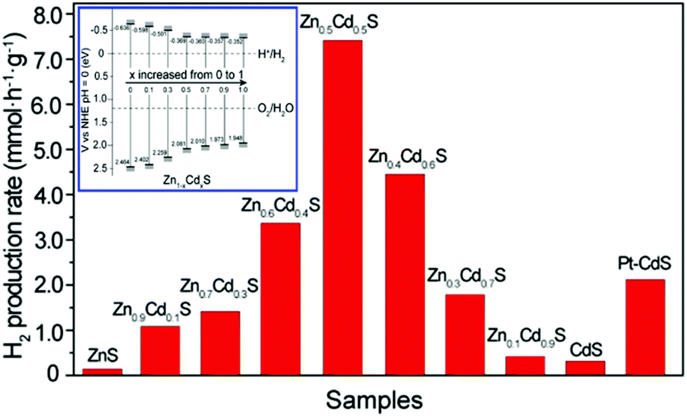 | ||
| Fig. 5 Comparison of the photocatalytic activities of Zn1−xCdxS samples with different compositions and a Pt (0.9 wt%)/CdS sample for the photocatalytic H2-production from 0.44 M Na2S and 0.31 M Na2SO3 mixed aqueous solution under visible-light irradiation. The inset is the conduction and valence band edge potentials of Zn1−xCdxS samples with different compositions. Reproduced with permission from ref. 57. Copyright 2013 American Chemical Society. | ||
3.3 Loading cocatalysts onto CdX
As discussed above, loading appropriate cocatalysts on the semiconductor photocatalyst can effectively promote or accelerate the surface chemical reactions.17,18,30 Generally, the cocatalysts for semiconductor-based photocatalytic water splitting can be divided into two categories according to their different functions, that is, H2-evolution cocatalysts and O2-evolution cocatalysts. In this section, we focus on the development of the combination of H2-evolution cocatalysts with CdX-based photocatalysts for photocatalytic H2 generation.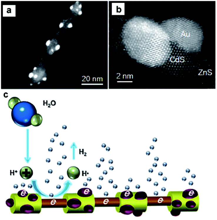 | ||
| Fig. 6 (a, b) HAADF-STEM images of the ZnS–(CdS/Au) hetero-nanorods. (c) Schematic representation of the photocatalytic generation of H2 from the hetero-nanorods. Reproduced with permission from ref. 74. Copyright 2015, John Wiley and Sons. | ||
| Photocatalyst | Cocatalyst | Light sourcea | Aqueous reaction solutionb | H2 evolution | Ref. | ||
|---|---|---|---|---|---|---|---|
| Activity (μmol h−1 g−1) | QE (%) | Enhancement factorc | |||||
| a Xe: xenon lamp, Hg: mercury lamp. b TEOA: triethanolamine, AA: ascorbic acid. c Enhanced factor is calculated from the activity enhancement of photocatalysts loaded with the optimal amount of cocatalysts over photocatalysts without the loading of cocatalysts. | |||||||
| Nanoporous CdS nanostructures | 13 wt% Pt | λ ≥ 420 nm (Xe) | 0.35 M Na2SO3 + 0.25 M Na2S | 27![[thin space (1/6-em)]](https://www.rsc.org/images/entities/char_2009.gif) 333 333 |
60.34 (420 nm) | 205 | 59 |
| CdSe-seeded CdS nanorods | Pt | 300 W Xe | Isopropanol | 40000 |
20 (450 nm) | 60 | |
| CdS | 0.3 wt% Pt + 0.13 wt% PdS | λ > 420 nm (Xe) | 0.5 M Na2SO3 + 0.5 M Na2S | 29233 |
93 (420 nm) | 381 | 61 |
| CdS | 1 wt% Pt | λ > 420 nm (Xe) | 0.1 M Na2SO3 + 0.1 M Na2S | 13800 |
22 (420 nm) | 62 | |
| CdSe nanorods | Pt | λ ≥ 420 nm (Xe) | 0.35 M Na2SO3 + 0.25 M Na2S | 36250 |
0.63 (454 nm) | 63 | |
| Multi-armed CdS nanorods | 0.23 wt% Pt | λ ≥ 420 nm (Xe) | 10 v% lactic acid | 24200 |
51 (420 nm) | 60.5 | 64 |
| Single crystal CdS nanowires | 0.3 wt% Pt | λ ≥ 420 nm (Xe) | 10 v% lactic acid | 18625 |
61.7 (420 nm) | 74.5 | 65 |
| Porous CdS nanosheet-based flowers | 0.5 wt% Pt | λ > 420 nm (Xe) | 10 v% lactic acid | 9374 | 24.7 (420 nm) | 66 | |
| Mixed-phase CdS | 0.3 wt% Pt | λ > 400 nm (Hg–Xe) | 0.02 M Na2SO3 + 0.1 M Na2S | 668 | 2 | 67 | |
| CdS | 1 wt% Pt | UV | 0.35 M Na2SO3 + 0.24 M Na2S | 6000 | 8.82 | 68 | |
| CdS | 1 wt% Pt | Overall spectrum | 0.3 M Na2SO3 + 0.2 M Na2S | 13860 |
1.3 (overall spectrum) | 3.3 | 69 |
| CdS nanorods | 0.05 wt% Pt | λ > 420 nm (Hg) | Formic acid | 4603.2 | 13.9 (>420 nm) | 21 | 70 |
| CdS | 1.5 wt% Pt | λ > 420 nm (Hg) | Formic acid | 1127.5 | 16.3 | 33 | |
| CdS nanowires | 1 wt% Pt | λ ≥ 420 nm (Hg) | 0.1 M Na2S + 0.02 M Na2SO3 | ∼60 | 71 | ||
| CdS | 3 wt% Pt | λ ≥ 420 nm (Hg) | 0.25 M Na2S + 0.35 M Na2SO3 | 83.3 | 32 | ||
| CdS | 2 wt% Pt | λ > 430 nm (Xe) | 0.25 M Na2SO3 + 0.35 M Na2S | 5625 | 24.1 (420 nm) | 5 | 72 |
| CdS nanowire arrays | 10 wt% Pt | λ ≥ 420 nm (Xe) | 0.25 M Na2SO3 + 0.35 M Na2S | 2600 | 7.2 (420 nm) | 73 | |
| CdS | 1 wt% Pt | UV | 0.35 M Na2SO3 + 0.24 M Na2S | 14150 |
19.4 | 40 | |
| ZnS–CdS heteronanorods | Pt | 300 W Xe | 0.25 M Na2SO3 + 0.35 M Na2S | 5050 | 7.5 | 74 | |
| CdSe/CdS core/shell nanowires | ∼30 wt% Pt | 450 W Xe | 0.1 M Na2SO3 + 0.1 M Na2S | 434.29 | 5.4 | 75 | |
| CdS–ZnO–CdO | 0.5 wt% Ru | 150 W Xe | 0.1 M Na2S + 0.04 M Na2SO3 | ∼75 | 50 | 76 | |
| CdS/Al–HMS | 0.07 wt% Ru | λ ≥ 420 nm (Xe) | Formic acid | 825.9 | 1.2 (420 nm) | 79 | |
| CdS | 4 wt% Ni | λ > 420 nm (Xe) | (NH4)2SO3 | 25848 |
26.8 (420 nm) | 83 | |
| CdS nanorods | Ni | 447 nm (LED) | Ethanol | 63000 |
53 (447 nm) | 84 | |
| CdS | 5 wt% Ni | λ > 400 nm (Xe) | 50 v% lactic acid | 30048 |
∼6.6 | 85 | |
| CdS–titanate | 1.2 wt% Ni | λ ≥ 420 nm (Xe) | 20 v% ethanol | 11038 |
21 (420 nm) | 77.7 | 88 |
| CdS | 32 mol% NiO | 500 W Phoenix tungsten halogen lamp | 0.25 M Na2SO3 + 0.35 M Na2S | 745 | 6.02 | 90 | |
| CdS | 13.2 mol% Ni2O3 | λ > 400 nm (Xe) | 30 v% methanol | 4456 | 4.1 | 91 | |
| CdS | 1 mol% NiOx | λ > 400 nm (Xe) | 30 v% methanol | 5908 | 8.6 (400 nm) | 117 | 92 |
| TiO2/CdS | 2.1 wt% CoOx | λ > 400 nm (Xe) | 0.125 M Na2S + 0.175 M Na2SO3 | 660 | 7 | 93 | |
| CdS | 3 mol% Co3O4 | λ ≥ 420 nm (Xe) | 0.5 M Na2S + 0.5 M Na2SO3 | 236 | 32.4 | 94 | |
| CdS | 3.5 mol% MoO3 | λ > nm (Xe) | 0.2 M Na2S + 1.5 M Na2SO3 | 5250 | 28.86 (420 nm) | 87.5 | 95 |
| CdS | 23 mol% Ni(OH)2 | λ > 420 nm (Xe) | 25 v% TEOA | 5085 | 28 (420 nm) | 145 | 96 |
| CdS/RGO | 1.0 wt% Ni(OH)2 | λ > 420 nm (Xe) | 0.25 M Na2SO3 + 0.35 M Na2S | 4731 | 10 | 97 | |
| Zn0.8Cd0.2S | 0.6 mol% Ni(OH)2 | λ ≥ 420 nm (Xe) | 20 v% TEOA | 7160 | 29.5 (420 nm) | 25.5 | 98 |
| CdS nanorods | 6.8 mol% Co(OH)2 | 500 W Xe | 25 v% methanol | 61 | 41 | 99 | |
| CdS | 0.2 wt% MoS2 | λ > 420 nm (Xe) | 10 v% lactic acid | ∼5400 | 36 | 101 | |
| CdSe | 0.5 wt% MoS2 | λ ≥ 420 nm (Xe) | 0.1 M Na2SO3 + 0.1 M Na2S | 890 | 3.7 | 102 | |
| CdS | 0.4 wt% RGO + 2 wt% MoS2 | 500 W UV lamp | 10 v% lactic acid | 6857 | 71 | 103 | |
| Zn0.2Cd0.8S | 3 wt% MoS2 | λ > 420 nm (Xe) | 0.25 M Na2SO3 + 0.35 M Na2S | 420 | 210 | 104 | |
| Zn0.3Cd0.7S | 0.6 wt% MoS2 | λ > 420 nm (Xe) | 10 v% lactic acid | 1196 | 7 | 106 | |
| CdS | 15 wt% MoS2 | λ > 420 nm (Xe) | 0.02 M Na2SO3 + 0.1 M Na2S | 4770 | 10 | 107 | |
| CdS | ∼11 mol% WS2 | λ > 420 nm (Xe) | 10 v% lactic acid | 1984 | 16 | 109 | |
| ∼7 mol% MoS2 | λ > 420 nm (Xe) | 10 v% lactic acid | 1472 | 12 | 109 | ||
| CdS | 1.0 wt% WS2 | λ > 420 nm (Xe) | 10 v% lactic acid | ∼4200 | 5.0 (420 nm) | 28 | 110 |
| CdSe/CdS | MoS3 | 450 nm (Hg–Xe) | TEOA | 100000 |
10 (450 nm) | 111 | |
| CdS | 1.2 mol% NiS | λ ≥ 420 nm (Xe) | 30 vol% lactic acid | 7267 | 51.3 (420 nm) | 34 | 112 |
| CdS nanorods | 5 mol% NiS | λ > 420 nm (Xe) | 0.25 M Na2SO3 + 0.35 M Na2S | 1131 | 6.1 (420 nm) | 20.6 | 113 |
| Zn0.5 Cd0.5 S/RGO | 3 mol% NiS | AM1.5 | 0.25 M Na2SO3 + 0.35 M Na2S | 7514 | 31.3 (420 nm) | 1.8 | 114 |
| Cd0.5Zn0.5S | 0.025 mol% NiS | λ ≥ 430 nm (Xe) | 0.25 M Na2SO3 + 0.35 M Na2S | 1400 | 33.9 (425 nm) | 3.5 | 115 |
| CdLa2S4 | 2 wt% NiS2 | λ ≥ 420 nm (Xe) | 0.25 M Na2SO3 + 0.35 M Na2S | 2500 | 1.6 (420 nm) | 3.1 | 118 |
| CdS nanorods | 3 mol% CuS | 500 W (Xe) | 0.25 M Na2SO3 + 0.35 M Na2S | 332 | 3.5 | 119 | |
| Zn0.5Cd0.5S | CuS | λ ≥ 420 nm (Xe) | 0.25 M Na2SO3 + 0.35 M Na2S | 4638.5 | 20.9 (420 nm) | 7 | 120 |
| Zn0.8Cd0.2S | 3 wt% CuS | 500 W (Xe) | 0.25 M Na2SO3 + 0.35 M Na2S | 2792 | 36.7 (420 nm) | 4.4 | 121 |
| CdS | 20 mol% SrS | λ ≥ 430 nm (Xe) | 0.25 M Na2SO3 + 0.35 M Na2S | 615 | 2.85 (420 nm) | 2 | 122 |
| CdS | ∼41.6 mol% TiS2 | λ > 399 nm (Xe) | 3.5 v% benzyl alcohol | 1000 | 2.9 | 123 | |
| CdS | ∼41.6 mol%TaS2 | λ > 399 nm (Xe) | 3.5 v% benzyl alcohol | 2320 | 6.9 | 123 | |
| CdS nanorods | 0.5 wt% Ni2P | λ > 420 nm (Xe) | 0.25 M Na2SO3 + 0.35 M Na2S | 1200000 |
41 (450 nm) | 22 | 125 |
| CdS nanorods | 16.7 wt% MoP | λ > 420 nm (Xe) | 10 v% lactic acid | 163200 |
5.8 (450 nm) | 9.2 | 126 |
| CdS nanorods | 0.44 wt% Cu3P | λ > 420 nm (Xe) | 1.25 M Na2S + 1.75 M Na2SO3 | 200000 |
25 (450 nm) | 6.6 | 127 |
| CdS nanorods | 30 wt% Fe2P | λ > 420 nm (Xe) | 0.5 M AA | 186000 |
15 (450 nm) | 31 | 128 |
| CdS | 10 wt% WC | λ ≥ 420 nm (Hg-arc) | 0.1 M Na2S + 0.02 M Na2SO3 | 1400 | 23 | 130 | |
For the cocatalyst loading onto the CdX semiconductors, a series of factors, such as the loading conditions, geometrical configuration of the semiconductors, and the size and composition of the cocatalysts, can greatly influence the final effect of the composite catalysts. For example, Xu and co-workers compared the photocatalytic activities of various Pt/CdS photocatalyst systems obtained from different Pt reduction environments for H2 production and investigated the effect of loading conditions for Pt nanoparticles on the surface of the CdS photocatalyst.62 In this study, Pt was deposited on the CdS photocatalyst by means of a photoreduction method. They found that the solution environment during Pt photoreduction played an essential role on the activity of the final Pt/CdS photocatalyst system. Study of the photocatalytic activity for H2 production from various Pt/CdS photocatalyst systems revealed that the sample with Pt reduced in NaOH alkaline solution exhibited a markedly higher H2 evolution activity (13 mmol h−1 g−1) than that of samples obtained in acidic or neutral solution (<0.5 mmol h−1 g−1) in the presence of Na2S and Na2SO3 as sacrificial reagents. Song et al. investigated geometrical (single- or double-tipped) and compositional (Pt or Au) variations of active metal components in a well-defined CdSe nanorod system.63 In this case, single Pt-tipped, single Au-tipped, double Pt-tipped, and double Au-tipped CdSe nanorods could be fabricated by controlling the component and the concentration of Pt (or Au) precursors. Study of their photocatalytic activities revealed that these catalysts exhibited significant dependency of the catalytic activity on the catalyst geometry and the choice of the noble metal tips. They found that the Pt-tipped catalysts showed higher photocatalytic activity than Au-tipped catalysts. Moreover, the H2 evolution amount of the single Pt-tipped CdSe nanorods was about ∼50% larger than that of the double Pt-tipped structure, although the loading amount of Pt in the former was only half of that in the latter (see Fig. 7).
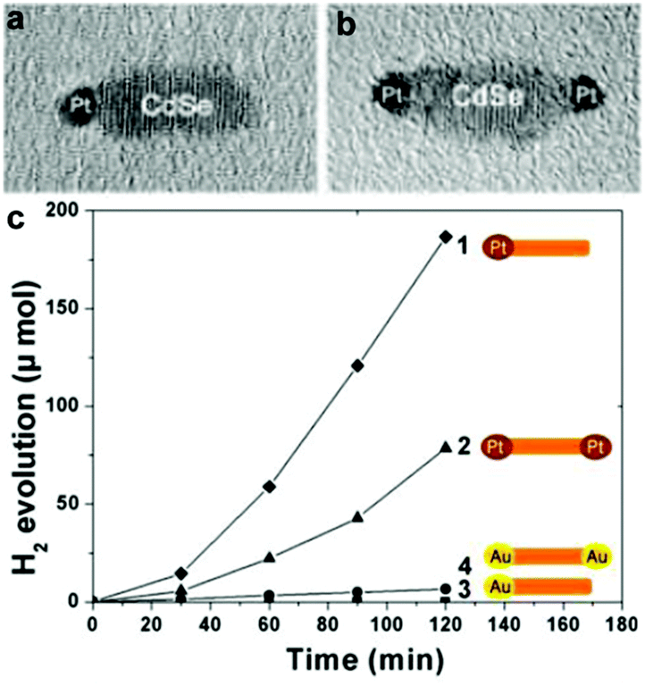 | ||
| Fig. 7 (a, b) Typical TEM images of single (a) and double (b) Pt-tipped CdSe nanorods. (c) Time course of H2 evolution by various photocatalysts: single Pt-tipped CdSe (◆), double Pt-tipped CdSe (▲), double Au-tipped CdSe (●), and single-Au tipped CdSe (■). Reproduced with permission from ref. 63. Copyright 2012 American Chemical Society. | ||
Recently, several earth-abundant transition metal H2-evolution cocatalysts, such as Ni83–88 and Co,89 have been used as substitutes for noble metals to enhance the activity of CdX photocatalysts. For example, Wang et al. reported enhanced activity for photocatalytic H2 generation in Ni/CdS nanocomposite photocatalysts.83 In their study, Ni nanoparticles with a high degree of crystallization and an average size of about 10 nm were prepared via chemical reduction of a NiCl2 precursor by hydrazine in an aqueous solution followed by loading on CdS nanorods by photo-induced deposition. They found that the loading of Ni nanoparticles could increase the specific surface area of CdS nanorods. Upon visible light irradiation, the Ni/CdS photocatalyst with a Ni content of 4 wt% could provide a H2 evolution rate of 25.8 mmol h−1 g−1 from aqueous (NH4)2SO3 solution with a QE of 26.8% at 420 nm. Moreover, the Ni/CdS nanocomposite photocatalyst could retain high stability and activity even after 20 h of photocatalytic reaction. Feldmann and co-workers also demonstrated efficient photocatalytic H2 production on Ni-decorated CdS nanorods.84 In this study, the Ni nanoparticles (2–8 nm) were loaded on the surface of the cysteine stabilized CdS nanorods through in situ photodeposition. They employed a hydroxyl anion/radical redox couple (˙OH/−OH), which possess good mobility and can react with CdS and the sacrificial agent (ethanol) to assist in the efficient transfer of the photogenerated holes from the CdS to ethanol (see Fig. 8). As a result, a significant enhancement in the H2 generation rate could be achieved, with an apparent QE of 53% at 447 nm and a remarkable H2 formation rate of 63 mmol g−1 h−1 under optimal conditions. Moreover, the obtained photocatalyst exhibited an excellent long-term stability (over 220 h) for photocatalytic H2 production. The work by Chen et al. showed that metallic Ni can be deposited on CdS by a hydrothermal reduction method with ethylene glycol.85 The optimal Ni (5 wt%)/CdS photocatalyst gave a H2 evolution rate of around 3 mmol h−1, which was even higher than that of the Pt(0.5 wt%)/CdS system under the same reaction conditions. More recently, Zhukovskyi et al. demonstrated efficient photocatalytic H2 generation from Ni nanoparticle-decorated CdS nanosheets.86 As an example of loading a Co cocatalyst onto CdX, Wu and co-workers demonstrated a robust catalyst system formed in situ from CdTe QDs and CoCl2·6H2O in aqueous ascorbic acid solution for photocatalytic H2 generation.89 In this case, the Co2+ ions, which were directly bonded to the surface of the CdTe QDs, could be photoreduced partially or completely under visible-light irradiation to form a hybrid Coh–CdTe catalyst system, which could achieve a high H2 evolution rate of 25 μmol h−1 mg−1 with a turnover number (TON) of 86250 with respect to the CdTe QDs with 21 h irradiation.
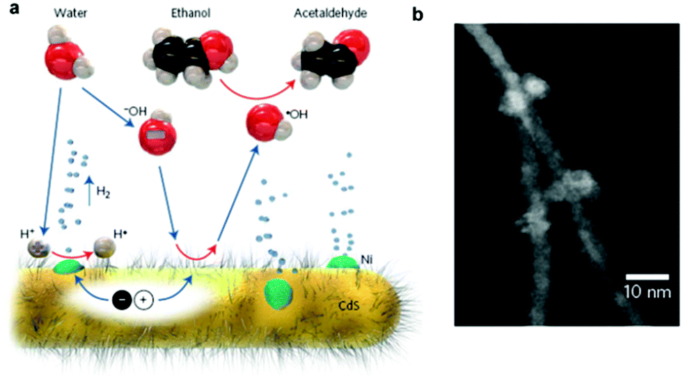 | ||
| Fig. 8 (a) Schematic of the photocatalytic generation of H2 from Ni-decorated CdS nanorods under the proposed hole shuttle mechanism. (b) HAADF-STEM image of the Ni-decorated CdS nanorods. Reproduced with permission from ref. 84. Copyright 2014, Nature Publishing Group. | ||
For example, Chen et al. showed that in situ photodeposition of NiOx on CdS could enhance its photocatalytic H2 generation activity. They found that the environment of deposition could affect the photocatalytic activity of the resultant NiOx–CdS photocatalyst.92 The NiOx–CdS photocatalyst formed in alkaline solution showed the highest activity of photocatalytic H2 production due to the high dispersion and tight deposition of NiOx on CdS, and better hole transfer under alkaline conditions, reaching 590.8 μmol h−1, which was 117 times higher than that of pure CdS. Yan et al. prepared a CoOx-loaded TiO2/CdS semiconductor composite by a simple solvothermal method.93 Study of their photocatalytic behaviour revealed that CoOx could act as an efficient cocatalyst to enhance the photocatalytic activity of TiO2/CdS and its content exhibited a significant influence on the activity. The optimal CoOx loading content was determined to be 2.1 wt%, and the average rate of H2 evolution was 660 μmol g−1 h−1 in the presence of Na2S and Na2SO3 as sacrificial agents, which is about 7 times higher than those of the TiO2/CdS composite and CdS. The work by Yuan et al. showed that Co3O4 can serve as an efficient H2-evolution cocatalyst in combination with CdS semiconductor.94
Several metal hydroxides96–99 and layered double hydroxides (LDH)100 have also been developed as efficient and noble metal-free cocatalysts for photocatalytic H2 production. Jaroniec, Yu and co-workers found highly efficient photocatalytic H2 production on a Ni(OH)2-loaded CdS photocatalyst. The optimal Ni(OH)2 (0.23 mol%)/CdS photocatalyst could achieve a visible-light H2-production rate as high as 5085 μmol h−1 g−1 and a QE of 28% at 420 nm.96 The H2-production rate on the Ni(OH)2-loaded CdS photocatalyst was 145 and 1.3 times higher than those of pure CdS and Pt (1 wt%)/CdS photocatalyst, respectively. Yan et al. demonstrated the use of Ni(OH)2 as an efficient cocatalyst on a CdS/reduced graphene oxide (CdS/RGO) composite photocatalyst for visible light-driven H2 production.97 The optimal Ni(OH)2 (1.0 wt%)/CdS/RGO photocatalyst could give a H2-production rate of 4731 μmol h−1 g−1, which is nearly 10 times higher than that of the CdS/RGO photocatalyst under the same conditions. The work by Zhang et al. showed that Co(OH)2-modified CdS nanorods exhibited a visible-light H2-production rate of 61 μmol h−1 g−1, which exceeded that of pure CdS by a factor of 41 (see Fig. 9).99 The outstanding H2-evolution activity of Co(OH)2 and the interface formed between the Co(OH)2 and CdS, which facilitates the electron transfer from CdS to Co(OH)2, were thought to be the main reasons for the enhanced photocatalytic activity. Hwang and co-workers prepared strongly coupled Zn–Cr–LDH–CdS nanohybrids through the electrostatically derived self-assembly of cationic Zn–Cr–LDH nanosheets and cationic CdS QDs with anionic linkers.100 They found that the hybridization of CdS with Zn–Cr–LDH leads to significant enhancement of the photocatlaytic activity of CdS for visible-light-induced H2 generation.
 | ||
| Fig. 9 (a) TEM image and (b) HRTEM image of the Co(OH)2-modified CdS nanorod. Reproduced with permission from ref. 99. Copyright 2014, American Chemical Society. | ||
MoS2 is a well-known cocatalyst for photocatalytic H2 production, which has been widely investigated on a variety of semiconductor photocatalysts. Li and co-workers studied the role of MoS2 as a cocatalyst loaded on CdS for photocatalytic H2 production.101 In this case, the MoS2/CdS photocatalyst system with highly dispersed MoS2 on CdS was prepared by impregnating CdS with an aqueous solution of (NH4)2MoS4, followed by treatment in a H2S flow at high temperature. This study showed that the activity of CdS can be enormously increased by loading MoS2 as a cocatalyst, and the activity of the MoS2/CdS photocatalyst system could be even higher than that of Pt/CdS. In another recent example, Zhang and co-workers prepared MS2–CdS (M = W or Mo) nanohybrids, with single-layer MS2 nanosheets with a lateral size of 4–10 nm selectively grown on the Cd-rich (0001) surface of wurtzite CdS nanocrystals via a facile one-pot wet-chemical method, for photocatalytic H2 production109 (Fig. 10a). The photocatalytic performance of the WS2–CdS and MoS2–CdS nanohybrids towards H2 production under visible-light irradiation (λ > 420 nm) was found to be about 16 and 12 times higher than that of pure CdS, respectively. The enhancement in activity was attributed to the large number of active sites of the single-layer MS2 nanosheets and the inherent p/n heterjunction formed between MS2 and CdS (Fig. 10b). The study by Zong et al. also demonstrated that the loading of WS2 onto CdS could significantly enhance the evolution of H2 from lactic acid solution under visible-light irradiation.110 Alivisatos and co-workers described the coating of amorphous MoS3 on CdSe-seeded CdS nanorods by means of a facile one-step thermal process.111 This study showed that the maximum H2-evolution rate could reach 100 mmol h−1 g−1 with a QE of 10% at 450 nm.
 | ||
| Fig. 10 (a) HR-TEM image of MoS2–CdS nanohybrids. (b) Schematic illustration of the photocatalytic process of MS2–CdS nanohybrids in lactic acid solution. Reproduced with permission from ref. 109. Copyright 2015, John Wiley and Sons. | ||
Besides MoS2, MoS3 and WS2, some other transition metal sulphides, such as NiS,112–117 NiS2,118 CuS119–121 and CoS,112,117 can also serve as efficient H2-evolution cocatalysts to boost the photocatalytic activity of CdX photocatalysts. By using a simple hydrothermal route, Xu and co-workers have prepared a NiS/CdS nanocomposite, with ultrafine NiS nanoparticles deposited on CdS nanoparticles, as a highly active photocatalyst for H2 production.112 The optimized NiS (1.2 mol%)/CdS photocatalyst could reach a visible-light-driven H2-evolution rate of 7.27 mmol h−1 g−1 using lactic acid as a sacrificial agent with a QE of 51.3% at 420 nm, which is even higher than that of the Pt (1 wt%)/CdS photocatalyst. They proposed that the loading of the NiS cocatalyst could not only efficiently promote the separation and transport of photogenerated electrons from the CB of CdS to the NiS nanoparticles but could also accelerate the electrochemical adsorption and desorption kinetics for H2 evolution through the following reactions (eqn (2) and (3)):
| NiS + e− + H+ →\; HNiS | (2) |
| HNiS + e− + H+ → NiS + H2 | (3) |
The study by Xue and co-workers showed that the loading of NiS2 co-catalyst resulted in remarkable enhancement for H2 production over the CdLa2S4 photocatalyst under visible light irradiation.118 The optimal hybrid photocatalyst with 2 wt% NiS2 loading exhibited a H2 production rate of 2.5 mmol h−1 g−1, which was more than 3 times higher than that of the pristine CdLa2S4 photocatalyst. Zhang et al. prepared CuS/CdS nanoposites by a simple hydrothermal and cation exchange method and investigated their photocatalytic acitivity for H2 produciton.119 They found that the loading of CuS as the cocatalyst could remarkably enhance the photocatalytic performance of CdS. The optimized CuS (3 mol%)/CdS displayed the highest photocatalytic activity, giving an H2 evolution rate of 332 μmol g−1 h−1, exceeding that of pure CdS by 3.5 times.
Recently, several transition metal phosphides have been developed as electrocatalysts and found to give excellent H2 evolution reaction activities. More recently, transition metal phosphides have been utilized as highly efficient H2-evolution cocatalysts to enhance the photocatalytic acitivity of CdX semiconductors.124–129 The work by Cao et al. has shown that the combination of CdS nanorods as the photocatalyst with water-soluble Ni2P nanoparticles (5–8 nm) as the cocatalyst could create a highly efficient, stable, nobel-metal-free photocatalytic system for H2 generation.124 Under the optimal conditions, this resulted in a photocatalytic system that could achieve a TON and turnover frequency (TOF) of 26300 and 2110 h−1, respectively, based on the Ni2P cocatalyst. Very recently, Du and co-workers have demonstrated an integrated nanostructure composed of CdS nanorods as the photocatalyst and Ni2P nanoparticles as the cocatalyst for visible light-driven H2 evolution.125 In this case, crystalline Ni2P nanoparticles were tightly anchored onto the one-dimensional CdS nanorods via an easy solvothermal method, forming a Ni2P/CdS heterostructure (Fig. 11a and b). Under optimal conditions, the Ni2P/CdS heterostructured photocatalyst could achieve a H2 evolution rate of up to ∼1200 mmol h−1 mg−1, giving a TON of ∼3270000 and a TOF of 36400 vs. Ni2P in 90 h. The apparent QE was ∼41% at 450 nm. The exceptional activity of this photocatalytic system was probably due to fast charge separation between the Ni2P and the CdS nanorods (Fig. 11c). Based on this study, they further employed other transition metal phosphides, such as MoP,126 CuP,127 and Fe2P,128 as H2-evolution cocatalysts combined with CdS semiconductors for photocatalytic H2 production.
 | ||
| Fig. 11 (a) HRTEM image and (b) high-magnification HRTEM image of Ni2P/CdS heterostructures. (c) A schematic describing an artificial photocatalytic H2 production system using CdS NRs as the photosensitizer and Ni2P as the cocatalyst. Reproduced with permission from ref. 125. Copyright 2015, The Royal Society of Chemistry. | ||
 | ||
| Fig. 12 (a) Schematic illustration of the self-assembly of CaI and MPA capped CdTe nanocrystals, and the light-induced H2 evolution of the self-assembled complex. (b) Schematic illustration of photocatalytic H2 production by the CdS:CaI complex. (a) Reproduced with permission from ref. 131. Copyright 2010, American Chemical Society. (b) Reproduced with permission from ref. 132. Copyright 2012, American Chemical Society. | ||
| Photocatalyst | Cocatalysta | Light sourceb | Solvent | Sacrificial reagentc | H2 evolution | Ref. | ||
|---|---|---|---|---|---|---|---|---|
| TON vs. cocatalyst | TOF vs. cocatalyst | QE (%) | ||||||
| a CaI: clostridium acetobutylicum [FeFe]-hydrogenase I, PAA: poly(acrylic acid), PEI: polyethylenimone, DHLA: dihydrolipoic acid. b TH: tungsten halogen lamp, Hg: mercury lamp, Xe: xenon lamp. c TEOA: triethanolamine, AA: ascorbic acid, TEA: triethylamine. | ||||||||
| CdTe | CaI | AM 3.0 (TH) | H2O | AA | 25 s−1 | 9 (532 nm) | 131 | |
| CdS | CaI | 405 nm (LED) | H2O | AA | ∼1000000 |
380 s−1 | 20 (405 nm) | 132 |
| AM 1.5 (LED) | H2O | AA | 983 s−1 | |||||
| CdTe | 1 | λ > 400 nm (Hg) | H2O | AA | 505 | 50 h−1 | 133 | |
| CdTe | 2 + chitosan | 410 nm (LED) | CH2OH/H2O | AA | 52800 |
∼1.4 s−1 | 134 | |
| CdSe | 3 | 410 nm (LED) | H2O | AA | 8781 | 596 h−1 | 135 | |
| CdSe | 4 + PAA | 450 nm (LED) | H2O | AA | 27135 |
3.6 s−1 | 5.07 (450 nm) | 136 |
| CdSe | 5 + PEI | 410 nm (LED) | H2O | AA | 10600 |
137 | ||
| CdS | 6 | λ > 420 nm (Xe) | CH3CN/H2O | TEOA | 171 | 9.1 (420 nm) | 138 | |
| CdSe/ZnS | 9 | λ > 400 nm (Xe) | Toluene | TEOA | >151 | 139 | ||
| CdTe | 10 | λ > 400 nm (Xe) | H2O | AA | 650 | 9 min−1 | 140 | |
| CdS | 11 | λ > 420 nm (Xe) | H2O | Na2SO3 + Na2S | 64700 |
29 (420 nm) | 141 | |
| CdTe | 12 | λ > 400 nm (Xe) | H2O | AA | 14400 |
850 h−1 | 5.32 (400 nm) | 142 |
| CdSe | Ni2+–DHLA | 520 nm (LED) | H2O | AA | >600000 |
7000 h−1 | 36 (520 nm) | 144 |
| CdS | 13 | λ > 420 nm (Xe) | C2H5OH/H2O | TEA | 28000 |
311 h−1 | 11.5 (420 nm) | 145 |
| CdSe | 21 | 520 nm (LED) | H2O | AA | 280000 |
146 | ||
Based on this early work, Brown et al. recently further employed CaI as a cocatalyst combined with colloidal CdS nanorods, which possess a larger absorption cross-section and surface area compared to CdTe nanocrystals, for photochemical H2 generation from water.132 The resultant CdS nanorod–CaI photocatalytic complexes could display a TOF of 380–900 s−1 (based on hydrogenase) and a QE of up to 20% under illumination at 405 nm using ascorbic acid as an electron donor (see Fig. 12b). The advances in these investigations not only demonstrate the feasibility of the integration of natural hydrogenase cocatalysts with CdX photocatalysts for a sustainable and economically viable H2 production, but also provide some deeper insight into the rational design and preparation of other hybrid photocatalytic systems comprising natural hydrogenases and inorganic semiconductors.
Despite hydrogenases being highly active for H2 evolution, the poor stability and the high cost of separation and purification of the enzymes from natural systems limit their large scale application. Relatively speaking, biomimetic molecular complexes capable of mimicking the active sites of hydrogenases and reproducing the enzymic activity seem to be more promising, as they are more tolerant to O2 and the structures are tunable. In recent years, many hybrid photocatalytic systems with CdX nanocrystals as photocatalysts and biomimetallic molecular complexes as cocatalysts have been developed for photochemical H2 generation. These hybrid systems were constructured either with molecular cocatalysts and CdX photocatalysts as two separate components or with molecular catalysts covalently linked to the surface of CdX photocatalysts. This section mainly focuses on the development of the hybrid photocatalytic systems comprising CdX photocatalysts and Fe-,133–137 Co-,138–143 Ni-144–147 and Cu-based148 biomimetic complexes as molecular cocatalysts, with some representative examples summarized in Table 2.
Since the structure of [FeFe]-hydrogenase ([FeFe]-H2ase) was resolved in 1998, many dinuclear [FeFe]-H2ase mimics have been synthesized and employed as H2 activation catalysts for both electrochemical and photochemical H2 evolution. The first example of the incorporation of a [FeFe]-H2ase mimic cocatalyst with a CdX photocatalyst was reported in 2011 by Wu and coworkers.133 In this study, a water soluble [FeFe]-H2ase mimic (1, Fig. 13) containing a hydrophilic isocyanide ligand in combination with MPA-stabilized CdTe QDs and ascorbate formed an efficient photocatalytic system for H2 production in fully aqueous solutions at pH 4. The TON and TOF reached up to 505 and 50 h−1 (based on 1) after 10 h of illumination (λ > 400 nm). The researchers proposed that there existed a significant interaction between MPA–CdTe and 1 in the ground state and the oxidative quenching of the excited MPA–CdTe by 1 was the dominant pathway for photocatalytic H2 evolution. Studies on a similar hybrid system with [Fe2(CO)6(μ-adt)CH2C6H5] (2, Fig. 13) as the molecular cocatalyst showed that the activity and stability of the [FeFe]-H2ase mimic were significantly improved by the addition of polysaccharide chitosan to mimic the protein matrix microenvironment surrounding the active site of [FeFe]-H2ases.134 The 2/MPA–CdTe QD/H2A system displayed a remarkable TON of 52800 for photochemical H2 evolution in MeOH/H2O at pH 4.5 in the presence of a large amount of chitosan (1.0 g L−1) over 60 h of irradiation with 410 nm LEDs, affording an initial TOF of ∼1.4 s−1 in the first 2 h. The TON of the H2 evolution and the stability of the system were significantly improved in the presence of chitosan, which was attributed to the fact that (i) the encapsulation of the MPA–CdTe QDs by polycationic chitosan prevented the QDs from aggregating and enhanced the emission quantum efficiency of the QDs and (ii) the intimate interaction of 2 and chitosan rendered the water insoluble catalyst well-dispersed in aqueous solution and improved the stability of the reduced species of 2. These results demonstrated that not only the structure of the active center but also the biological environment surrounding the center in natural [FeFe]-H2ases should be taken into account when designing and fabricating active H2 evolution systems based on [FeFe]-H2ase mimics.
 | ||
| Fig. 13 Structures of [FeFe]-H2ase mimics 1–3 used as cocatalysts in hybrid systems with CdX nanocrystals. (1) Reproduced with permission from ref. 133. Copyright 2011, John Wiley and Sons. (2) Reproduced with permission from ref. 134. Copyright 2013, Nature Publishing Group. (3) Reproduced with permission from ref. 135. Copyright 2013, The Royal Society of Chemistry. | ||
For most [FeFe]-H2ase mimics, their poor solubility in water is a critical drawback which limits their application for coupling with water splitting technology. In order to solve this problem, Wu and co-workers developed an effective strategy for interface-directed assembly of a simple [FeFe]-H2ase mimic, [Fe2S2(CO)6] (3, Fig. 13), onto the surface of CdSe QDs, forming a water-soluble photocatalytic system for H2 producton.135 Under optimal conditions, the 3/MPA–CdSe assembly system was able to reach a TON of 6530 based on 3 in water at pH 4.0 over 82 h of illumination with λ > 400 nm. A higher TON of 8781 was obtained when the same hybrid system was irradiated with 410 nm LEDs under otherwise identical conditions, giving a TOF of 596 h−1 in the first 4 h. The high efficiency and good durability of this system for photocatalytic H2 production were ascribed to the close contact between the CdSe QDs and 3. In addition to direct anchoring of the [FeFe]-H2ase mimic to the QDs, the other strategy used by Wu and co-workers was to coanchor the [FeFe]-H2ase mimic and the QDs to the side chain of a functionalized polymer.136 In this case, both [FeFe]-H2ase mimic 4 (Fig. 14a) and MPA–CdSe QDs were linked to the abundant carboxy groups in poly(acrylic acid) (PAA), leading to a short distance between the light harvester and the catalyst. PAA could enhance the emission of the MPA–CdSe QDs and prevent the MPA–CdSe nanoparticles from aggregating. The PAA–4/MPA–CdSe/H2A system in water at an initial pH of 4.0 displayed a TON of H2 evolution of up to 27135 over 8 h of irradiation with 450 nm LEDs, affording a TOF of 3.6 s−1 in the first half hour and a QE of 5.07%. Similarly, [FeFe]-H2ase mimic 5 (see Fig. 14b) was anchored on branched polyethylenimone (PEI) to generate a water-soluble [FeFe]-H2ase mimic, which then was coupled with MPA-capped CdSe QDs to create an efficient artificial photocatalytic system for H2 evolution.137
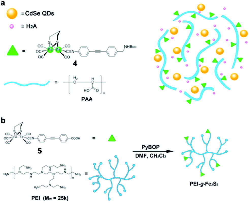 | ||
| Fig. 14 (a) Proposed scaffold for the hybrid system of PAA–4/MPA–CdSe QDs. (b) Schematic illustration of the synthetic route of PEI-g-Fe2S2 (5) production. (a) Reproduced with permission from ref. 136. Copyright 2013, John Wiley and Sons. (b) Reproduced with permission from ref. 137. Copyright 2015, John Wiley and Sons. | ||
Some molecular cobalt complexes are also employed to combine with CdX nanocrystals for photocatalytic H2 production.138–143 For example, by using CdS nanoparticles as the photocatalyst and cobaloxime complexes (6–8, Fig. 15) as molecular cocatalysts, Li and co-workers have demonstrated an efficient hybrid system for efficient photocatalytic H2 evolution.138 In this system, they found the physical adsorption of cobaloxime complexes on the surface of CdS particles facilitated the interfacial electron transfer from photoexcited CdS to cobaloxime complexes. Among various combinations of cobaloxime complexes with CdS, the cobaloxime 6/CdS hybrid system showed the highest activity for H2 production from a TEOA/H2O/CH3CN solution, giving a TON of 171 (based on 6) for H2 generation over 15 h of irradiation (λ > 420 nm) and a QE of 9.1% at 420 nm. In another example, a cobaloxime complex 9 (Fig. 15) was anchored onto the surface of CdSe/ZnS core/shell QDs via a phosphonate linkage, generating a hybrid system.139 In such a system, the ZnS shell could greatly improve the photostability and fluorescence quantum efficiency of the QDs compared with CdSe without the shell. Consequently, the cobaloxime 9/CdSe/ZnS system was capable of catalyzing H2 generation photochemically in the presence of a proton source (triethylamine hydrochloride) and a sacrificial agent (TEOA) in toluene, giving a TON of over 10000 H2 per QD in 10 h. The work by Llobet et al. showed that the integration of a molecular cobalt cocatalyst 10 (Fig. 15) with CdTe QDs could result in efficient light-induced proton reduction to molecular H2.140 Chen et al. reported an efficient artificial photocatalytic system, consisting of CdS nanorods as the photocatalyst and Co-based complex 11 (Fig. 15) as a molecular cocatalyst for H2 generation.141 Also, Sun and co-workers demonstrated that a hybrid system with a coordinative interaction between a Co complex 12 (Fig. 15) and CdTe QDs displayed high activity and improved stability for photochemical H2 generation form water.142
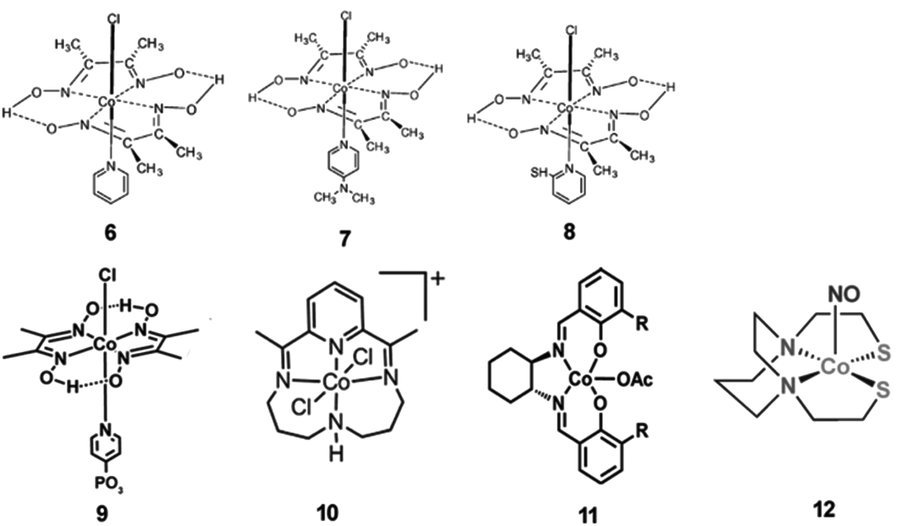 | ||
| Fig. 15 Structures of Co-based complexes 6–12 used as cocatalysts in hybrid systems with CdX nanocrystals. (6–8) Reproduced with permission from ref. 138. Copyright 2011, Elsevier. (9) Reproduced with permission from ref. 139. Copyright 2012, American Chemical Society. (10) Reproduced with permission from ref. 140. Copyright 2014, American Chemical Society. (11) Reproduced with permission from ref. 141. Copyright 2015, The Royal Society of Chemistry. (12) Reproduced with permission from ref. 142. Copyright 2015, The Royal Society of Chemistry. | ||
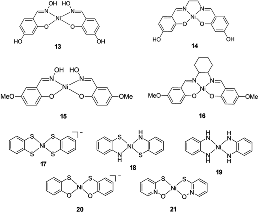
In recent years, several molecular nickel complexes have been proved to be effective molecular cocatalysts in conjunction with CdX photocatalysts for photochemical H2 evolution. In 2012, Krauss and coworkers showed that the integration of an in situ-formed Ni-based complex, Ni2+–DHLA (DHLA = dihydrolipoic acid) with DHLA-capped CdSe nanocrystals could create a highly active and superiorly stable hybrid system for visible-light-driven H2 generation144 (see Fig. 16). Upon irradiation of this catalytic system with 520 nm LEDs, a TON of more than 600000 (based on the Ni catalyst) and an initial TOF of 7000 h−1 were obtained in the presence of ascorbic acid as the electron donor, corresponding to a QE of over 36%. Moreover, this catalytic system presented undiminished activity for over 360 h. Very recently, by employing CdS nanosheets (∼4 nm in thickness) as the photocatalyst and Ni-based complexes (13–16, see Fig. 17) as the molecular cocatalysts, our droup demonstrated an efficient noble metal-free artificial photocatalytic system for H2 production.145 Among the CdS-complex systems containing various molecular nickel complexes (13–16), the CdS/complex 13 catalyst system exhibited the highest activity for H2 production, and could generate H2 with a TON of over 28000 (based on complex 13) in a TEA/CH3OH/H2O solution. We ascribed the high activity of this hybrid photocatalytic system to improvement in charge carrier separation and the efficient electron transfer from the CdS nanosheet to molecular nickel complexes. The work by Das et al. demonstrated Ni-based complexes (17–21, Fig. 17) for robust light-driven H2 production from water in combination with CdSe QDs as the photocatalyst.146 Wang et al. reported the integration of Ni–DMSA complexes (DMSA = meso-2,3-dimercaptosuccinic acid) with DMSA capped CdSe/CdS core/shell nanocrystals for efficient photocatalytic H2 production.147
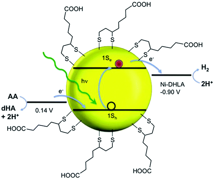 | ||
| Fig. 16 Cartoon illustration of the relevant energies for H2 evolution (at pH 4.5). AA and dHA indicate ascorbic acid and dehydroascorbic acid, respectively. Reproduced with permission from ref. 144. Copyright 2012, The American Association for the Advancement of Science. | ||
 | ||
| Fig. 17 Structures of Ni-based complexes 13–21 used as cocatalysts in hybrid systems with CdX nanocrystals. (13–16) Reproduced with permission from ref. 145. Copyright 2015, John Wiley and Sons. (17–21) Reproduced with permission from ref. 146. Copyright 2015, American Chemical Society. | ||
Molecular copper complexes used for photochemical H2 production in combination with CdX photocatalysts were less reported compared with iron, cobalt and nickel complexes. Zhang and co-workers showed that a copper(I) cysteine complex formed by mixing Cu(II) ions with cysteine in aqueous solution could greatly enhance the activity of a CdSe photocatalyst for H2 evolution under visible light irradiation.148 Differing from the other molecular cocatalysts mentioned above, the copper(I) cysteine complex functioned as an oxidation cocatalyst, which could accept the photogenerated holes from the VB of CdSe and complete its catalytic cycles with a high reaction rate. Under optimal conditions, the copper(I) cysteine complex could enhance the H2 evolution rate by as much as 150 times.
3.4 Hybridization of CdX with other semiconductors
The combination of CdX photocatalysts with another wider bandgap semiconductor to form heterogeneous photocatalysts is an effective avenue to improve their photoactivity. Among them, CdS/TiO2 systems have undergone the most extensive studies.149–167 For example, Lee et al. combined CdS nanowires with TiO2 nanoparticles and fabricated a CdS/TiO2 heterogeneous photocatalyst.149 They proved that these CdS/TiO2 heterogeneous photocatalysts exhibited a significantly higher H2 evolution rate than CdS nanowires alone under the same conditions. Park et al. synthesized a series of ternary hybrid composites composed of CdS, TiO2 and Pt and systematically investigated the effects of varied combinations of the components on the photocatalytic activity for H2 generation.157 The authors found that the separation and transfer behaviours of the photogenerated charge carriers were greatly affected by how the ternary hybrid composites were organized. For achieving high efficiency in charge carrier separation, direct particle-to-particle contact between CdS and TiO2 was required, which facilitates the photogenerated electron transfer from CdS to TiO2. Moreover, the activity of the ternary hybrid photocatalysts was found to be extremely sensitive to the loading position of Pt on the CdS–TiO2 composite. The [CdS–(Pt/TiO2)] nanocomposite formed by photodeposition of Pt nanoparticles onto TiO2, followed by the loading of CdS onto the Pt/TiO2, showed the highest H2 evolution rate (Fig. 18c).
 | ||
| Fig. 18 Illustrative diagrams of the electron transfer in various hybrid photocatalysts comprising CdS, TiO2, and Pt. Reproduced with permission from ref. 157. Copyright 2008, The Royal Society of Chemistry. | ||
By means of a hydrothermal assisted ion-exchange route, Hou et al. have synthesized heterogeneous CdS@TaON with a core–shell structure.168 In such a structure, both the n-type CdS and p-type TaON can be excited to generate electron–hole pairs under visible-light irradiation. The resultant CdS@TaON core–shell structure could generate p–n heterojunctions between the two semiconductors due to the CB position of CdS being more negative than that of TaON, while the VB position of TaON was more positive than that of CdS. Consequently, the photogenerated electrons could be transported from CdS to TaON while the holes were transported from TaON to CdS. Study of their photocatalytic activity for H2 evolution from an aqueous solution of Na2S and Na2SO3 showed that the optimized (1 wt%) CdS@TaON heterogeneous photocatalyst could achieve a H2 production rate of 1.53 mmol h−1 g−1 by loading 0.4 wt% Pt cocatalyst under visible-light illumination, which was much higher than those of TaON (0.045 mmol h−1 g−1) and CdS (0.0675 mmol h−1 g−1) under the same conditions. Further, they found that the rate of H2 production can be raised to a higher value by coupling the CdS@TaON heterogeneous photocatalyst containing 0.4 wt% Pt with 1 wt% graphene, reaching 3.315 mmol h−1 g−1 with a QE of 31% at 420 nm.
Several CdX-based heterogeneous photocatalysts based on Z-scheme combination have been exploited for efficient photocatalytic H2 production.172–180 In a typical example, Tada et al. have successfully prepared an anisotropic CdS–Au–TiO2 nanojunction, in which CdS, TiO2 and the electron-transfer medium (Au) were all spatially fixed.172 As illustrated in Fig. 19, small Au nanoparticles (∼3.4 nm) were tightly anchored onto the antase TiO2, while CdS was coated on Au nanoparticles, forming Au@CdS/TiO2. In this three-component CdS–Au–TiO2 nanojunction, photogenerated electrons could migrate from TiO2 to Au and to CdS under UV-light irradiation. Consequently, these photoinduced electrons confined in the CB of CdS could drive the reductive reaction, while photoinduced holes kept in the VB of TiO2 could function in the oxidation reaction. Moreover, this Z-scheme combination can also restrict the photocorrosion of CdS because photogenerated holes in CdS can be recombined with electrons from TiO2via the electron-transfer medium (Au). Consequently, this three-component photocatalyst system exhibited high photocatalytic activity, far exceeding those of single- and two-component systems. What is more, they found that the H2 evolution rate can be further accelerated by selective deposition of an appropriate amount of Pt onto the surface of the catalyst. In a recent example, Cha and co-workers demonstrated enhanced H2 production from a novel DNA-assembled Z-scheme TiO2–CdS photocatalyst system.175 In this study, DNA was used to assemble Pt@CdS nanorods and TiO2 nanoparticles into a well-organized Z-scheme photocatalyst system, which exhibited a significant improvement in H2 production compared to either single photocatalyst or unassembled, dispersed catalyst mixtures. The work by Zhang et al. demonstrated an efficient Z-scheme photocatalyst system consisting of CdS and WO3 for visible-light driven H2 produciton.176
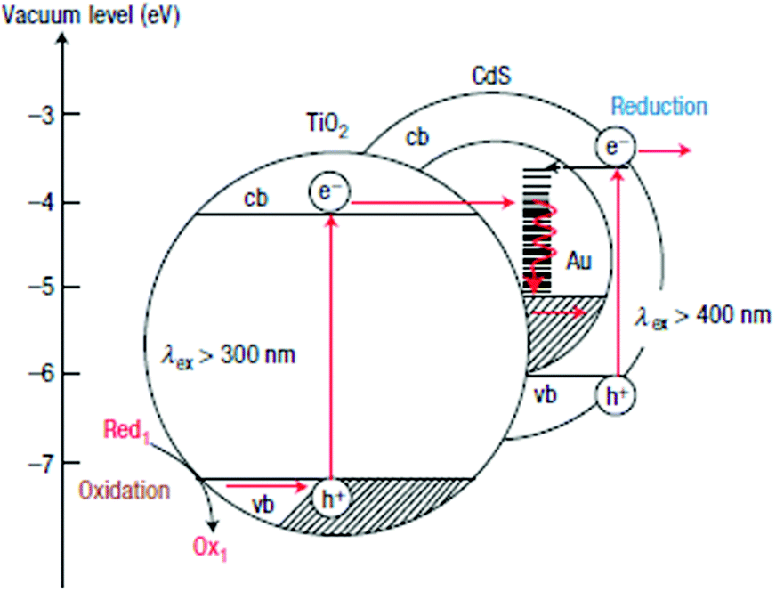 | ||
| Fig. 19 Energy and diagram scheme of the CdS–Au–TiO2 three-component systems. Reproduced with permission from ref. 172. Copyright 2006, Nature Publishing Group. | ||
3.5 Hybridization of CdX with carbon-based materials
Many carbon-related nano-structured materials such as carbon nanotubes (CNTs),181–187 graphene or its derivatives,97,103,114,188–202 and graphitic carbon nitride (g-C3N4)203–209 are also widely used to stabilize and enhance the photoactivity of CdX semiconductors, as summarized in Table 3.| Photocatalyst | Optimized mass fraction of carbon-based material | Cocatalyst | Light sourcea | Aqueous reaction solutionb | H2 evolution | Ref. | ||
|---|---|---|---|---|---|---|---|---|
| Activity (μmol h−1 g−1) | QE (%) | Enhancement factorc | ||||||
| a Xe: xenon lamp. b TEOA: triethanolamine, AA: ascorbic acid. c Enhancement factor refers to the enhancing times of photocatalyst H2 generation rate of photocatalyst system containing CdX and carbon-based materials, compared to pure CdX photocatalyst. | ||||||||
| MWCNTs/CdS | 10 wt% | λ ≥ 420 nm (Xe) | 0.25 M Na2SO3 + 0.35 M Na2S | 4977 | 2.16 (420 nm) | 1.8 | 181 | |
| CNTs/Cd0.1Zn0.9S | 0.25 wt% | λ ≥ 420 nm (Xe) | 0.25 M Na2SO3 + 0.35 M Na2S | 1564 | 7.9 (420 nm) | 3.2 | 183 | |
| Zn0.83Cd0.17S/CNTs | 300–800 nm (Xe) | 0.02 M Na2SO3 + 0.1 M Na2S | 6030 | 1.5 | 184 | |||
| CdS/CNTs | 4 wt% | 0.75 wt% NiS | λ > 420 nm (Xe) | 0.25 M Na2SO3 + 1.0 M Na2S | 12130 |
15 | 186 | |
| Zn0.83Cd0.17S/CNTs | 0.25 wt% | 500 W Xe lamp | 0.02 M Na2SO3 + 0.1 M Na2S | 5410 | 1.3 | 187 | ||
| CdS/RGO | 1 wt% | 0.5 wt% Pt | λ ≥ 420 nm (Xe) | 10 vol% lactic acid | 56000 |
22.5 (420 nm) | 45.6 | 188 |
| CdS/GO | 5 wt% | λ ≥ 420 nm (Xe) | 0.25 M Na2SO3 + 0.35 M Na2S | 3140 | 4.8 (420 nm) | 1.3 | 189 | |
| CdS/RGO | 10 wt% | λ ≥ 420 nm (Xe) | 0.25 M Na2SO3 + 0.35 M Na2S | 4200 | 10.4 (420 nm) | 1.5 | 190 | |
| CdS/RGO | 1 wt% | λ ≥ 420 nm (Xe) | 0.05 M Na2SO3 + 0.1 M Na2S | 700 | 4.8 | 191 | ||
| CdS–MoS2/graphene | 1.33 wt% | 0.67 wt% MoS2 | λ ≥ 420 nm (Xe) | 20 vol% lactic acid | 9000 | 28.1 (420 nm) | 72 | 192 |
| CdS–Al2O3/GO | 1 wt% | 500 W Phoenix tungsten halogen lamp | 0.25 M Na2SO3 + 0.35 M Na2S | 1750 | 14 (420 nm) | 4.2 | 193 | |
| CdS–ZnO/GO | 1 wt% | 500 W Phoenix tungsten halogen lamp | 0.25 M Na2SO3 + 0.35 M Na2S | 3755 | 30 (420 nm) | 9.0 | 193 | |
| CdS–ZnO/RGO | 2 wt% | 300 W Xe lamp | 0.1 M Na2SO3 + 0.1 M Na2S | 5100 | 34.0 | 194 | ||
| CdS–TaON/RGO | 1 wt% | 0.4 wt% Pt | λ ≥ 420 nm (Xe) | 0.04 M Na2SO3 + 0.1 M Na2S | 3165 | 31 (420 nm) | 195 | |
| CdS QDs–ZnIn2S4/RGO | 1 wt% | 0.4 wt% Pt | λ ≥ 420 nm (Xe) | 0.04 M Na2SO3 + 0.1 M Na2S | 27000 |
56 (420 nm) | 196 | |
| Zn0.8Cd0.2S/RGO | 0.25 wt% | AM 1.5G (Xe) | 0.25 M Na2SO3 + 0.35 M Na2S | 1824 | 23.4 (420 nm) | 4.5 | 197 | |
| CdS/N-doped graphene | 2 wt% | λ ≥ 420 nm (Xe) | 0.1 M Na2SO3 + 0.1 M Na2S | 1050 | 5.3 | 198 | ||
| CdS/sulfonated graphene | 2 wt% | Metal halide lamp, λ ≥ 380 nm | 0.07 M Na2SO3 + 0.05 M Na2S | 166 | 199 | |||
| CdS/cysteine-modified RGO | 0.7 wt% | 2.1 wt% Pt | λ ≥ 420 nm (Xe) | 10 vol% lactic acid | 29861 |
50.7 (420 nm) | 200 | |
| CdS/RGO | 5 wt% | 0.5 wt% Pt | λ ≥ 420 nm (Xe) | 1.25 M (NH4)2SO3 | 29400 |
7.3 | 202 | |
| g-C3N4/CdS | 1 wt% | 1 wt% Pt | λ ≥ 420 nm (Xe) | 0.25 M Na2SO3 + 0.35 M Na2S | 5303 | 3.6 (420 nm) | 2.5 | 208 |
| CdS-g-C3N4 | 88 wt% | 0.5 wt% Pt | λ ≥ 420 nm (Xe) | 0.1 M AA | 4494 | 8.0 (420 nm) | 1.8 | 204 |
| g-C3N4–CdS | 85 wt% | 9 wt% NiS | λ ≥ 420 nm (Xe) | 10 vol% TEOA | 2563 | 4.4 | 209 | |
| CdS-g-C3N4 | 2 wt% | 0.6 wt% Pt | λ ≥ 420 nm (Xe) | 0.25 M Na2SO3 + 0.35 M Na2S | 4152 | 4.3 (420 nm) | 2 | 205 |
Peng et al. reported a hydrothermal method for the direct growth of CdS nanoparticles (12–28 nm) on the surface of modified CNTs and successfully obtained CdS/CNT heterogeneous photocatalysts with different contents of CNTs.181 In such a heterostructure, CdS nanoparticles were deposited on the outer surfaces of the CNTs, which resulted in an intimate contact between the CdS nanoparticles and CNTs. The researchers demonstrated that those CdS/CNT heterogeneous photocatalysts with appropriate CNT contents exhibited much higher H2 evolution rates than CdS alone. The optimal 10 wt% CdS–CNT photocatalyst system showed a H2-evolution rate as high as 4.97 mmol h−1 g−1, while the H2 evolution rate over pure CdS nanoparticles was only 2.80 mmol h−1 g−1. Moreover, they found that the presence of CNTs could enhance the stability of the catalyst and suppress the photocorrosion of CdS. Kim and co-workers fabricated ternary nanocomposites of CdS–CNT–M (M represents a transition metal) and studied their photocatalytic activity for H2 production.182 In this case, M was first deposited on CNTs, which were pretreated with acid, by means of chemical reduction with NaBH4, followed by the loading of CdS nanoparticles on the as-obtained CNT/M, forming CdS/CNT/M three-component nanocomposites. The authors compared the activities of a series of CdS/CNT/M catalysts containing various M species and demonstrated that the CdS/CNT/Pt system exhibited the highest rate of H2 evolution (∼0.825 mmol h−1 g−1), which was obviously higher than that over its CdS/CNT counterpart (see Fig. 20). The study by Yu and co-workers showed that the H2-evolution activity of a Cd0.1Zn0.9S photocatalyst could be improved by loading an appropriate amount of CNTs. The optimal 0.25% CNT/Cd0.1Zn0.9S photocatalyst system could achieve a H2-generation rate of 1.56 mmol h−1 g−1 with a QE of 7.9% at 420 nm.
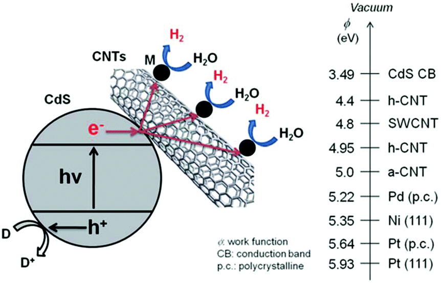 | ||
| Fig. 20 Illustration of photocatalytic H2 production in CdS/CNT/M suspensions under light irradiation. M and D refer to metal catalyst and electron donor (Na2S and Na2SO3), respectively. On the right-hand side, the reported work functions of selected materials are given. Reproduced with permission from ref. 182. Copyright 2011, The Royal Society of Chemistry. | ||
Gong, Yu and co-workers reported a highly-efficient CdS/graphene heterogeneous photocatalyst for photocatalytic H2 production from water splitting under visible-light irradiation.188 This CdS/graphene system was fabricated by means of a facile solvothermal method. The optimal CdS/graphene (1.0 wt%) photocatalyst system could achieve a high H2-production rate of 56 mmol h−1 g−1 with loading of 0.5 wt% Pt cocatalyst (about 4.87 times higher than that of pure CdS nanoparticles), corresponding to an apparent QE of 22.5% at 420 nm. The authors demonstrated that graphene in the CdS/graphene system could serve as an electron collector and transporter to efficiently lengthen the lifetime of photogenerated charge carriers from the CdS nanoparticles (see Fig. 21), which led to enhanced photocatalytic activity for H2 generation. The work by Zhang et al. showed that a nanocomposite photocatalyst consisting of reduced graphene oxide and ZnxCd1−xS exhibited high activity for photocatalytic H2 production.197 Some modified graphene materials have also been incorporated with semiconductors to improve their photocatalytic properties.198–200 In a typical example, Jia and co-workers coupled CdS with N-doped graphene to construct a highly-efficient photocatalyst system.198 At an optimal content of N-graphene (2 wt%), the rate of H2 production over CdS/N-graphene reached 1.05 mmol h−1 g−1, while the H2 evolution rates over CdS/graphene and the pure CdS counterpart were only 0.495 mmol h−1 g−1 and 0.2 mmol h−1 g−1, respectively. They clarified that graphene doped with N could effectively alter the electron density of states in graphene and enhance the conductivity of graphene. Moreover, the N-graphene could act as a protective layer to effectively prevent photocorrosion of CdS under irradiation during the photocatalytic process. Furthermore, Wang and co-workers compared the photocatalytic activity of CdS/graphene and CdS/CNT heterogeneous photocatalysts under the same conditions.201 In this case, CdS nanoparticles (∼35 nm) were loaded on graphene sheets or the outer surfaces of CNTs, forming heterogeneous photocatalysts. They found that the H2-production rate over the optimal CdS/graphene system (0.7 mmol h−1 g−1) was higher than that of the optimal CdS/CNT counterpart (0.52 mmol h−1 g−1). Noticeably, the H2-production rates over both the CdS/graphene and CdS/CNT systems were higher than that of the single CdS photocatalyst (0.145 mmol h−1 g−1). The researchers attributed the enhancement in photocatalytic activity over the CdS/graphene photocatalyst system to the stronger interactions or the larger contact interface between CdS and graphene. These results demonstrated that by taking the advantages of carbon-related materials in composites, the photocatalytic activity and stability of semiconductors can be remarkably improved.
 | ||
| Fig. 21 (a) TEM and (b) HRTEM images of graphene decorated with CdS clusters. The inset of (b) shows the SAED pattern. (c) Schematic illustration of the charge separation and transfer in the graphene–CdS photocatalyst system under visible light. Reproduced with permission from ref. 188. Copyright 2011, American Chemical Society. | ||
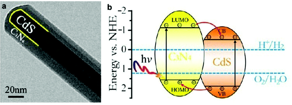 | ||
| Fig. 22 (a) TEM image of the CdS/g-C3N4 core/shell nanowire. (b) Schematic illustration of the energy-level configuration and the photogenerated charge-transfer process between g-C3N4 and CdS. Reproduced with permission from ref. 205. Copyright 2013, American Chemical Society. | ||
4. Conclusions and future perspective
The last few decades have witnessed a sustained increase in research attention on semiconductor-based photocatalysis applications. In the present review, we selectively summarized and analyzed the recent progress in photocatalytic water splitting for H2 production mediated by CdX semiconductors. It is encouraging that the efficiencies of photocatalytic H2 production with CdX-based photocatalysts have been tremendously improved, benefiting from the great advances in materials science and nanotechnology during the past few decades.Bulk CdX semiconductors alone display low photoactivity and bad stability for H2 production due to the ultrafast surface/bulk recombination of photogenerated charge carriers and the large H2 evolution overpotential, while researchers have made great achievements in designing and synthesizing CdX materials, especially those of nanoscale size, with controlled size, shape, morphology and crystal structure, to improve their photocatalytic performance. To further address the issues of low activity and bad stability in photocatalysis, current efforts are focused on the modification of CdX with other materials to enhance their photocatalytic activity and stability. Promising strategies, such as forming a solid solution, loading with cocatalysts and hybridization with other semiconductors or carbon-based materials, have been widely developed for CdX semiconductors to maximize their photoactivity. These strategies can significantly facilitate separation and migration of photogenerated electrons and holes, reduce charge recombination probability, improve photoactivity and prolong the functional life-time of photocatalysts.
Despite this progress, several challenges still need to be addressed to obtain a satisfying H2 production efficiency from solar water splitting. Firstly, the current state-of-the-art CdX-based photocatalyst systems are still far from being used for sustainable H2 production from water with both economic and environmental benefits. Secondly, the photocorrosion of CdX under irradiation in the photocatalytic process and the poor photostability are still key problems obstructing large-scale application. Thirdly, for most of the CdX-based heterogeneous photocatalyst systems, the interrelationships among compositions, microstructures and photocatalytic performance give no clear and systematic answers. Additionally, introducing additional electron donors (sacrificial reagents) to achieve efficient H2 production from water is needed in most of the current photocatalytic systems.
In order to address these challenges and promote the further development of CdX-based photocatalytic H2 production, further work in this field should be focused on the following aspects: (i) exploiting novel CdX-based photocatalysts with controlled structure, composition and morphology and tuning their light absorption properties, bandgaps and the band-edge positions; (ii) conducting more in-depth theoretical and computational studies to probe the interrelationships among compositions, microstructures and photocatalytic properties; (iii) developing more novel and effective modification strategies to enhance the photocatalytic activity and stability of CdX semiconductors; (iv) exploring more new characterization technologies to uncover the photogenerated charge carrier transfer dynamics and the mechanism of H2 production in heterogeneous photosynthetic systems, which can purposefully direct the design and synthesis of highly efficient photocatalysts; (v) constructing highly efficient photocatalytic systems to achieve overall water splitting from pure water without needing extra sacrificial reagents and organic solvents. Continued research in this exciting field will surely accelerate the development of photocatalytic water splitting technology and open new opportunities for extension to other semiconductor-based photocatalytic applications, such as pollutant photodegradation, CO2 photoreduction and organic photosynthesis.
Acknowledgements
We appreciate the National Natural Science Foundation of China (no. 21422104) for financial support.Notes and references
- Y. Tachibana, L. Vayssieres and J. R. Durrant, Nat. Photonics, 2012, 6, 511 CrossRef CAS.
- N. Armaroli and V. Balzani, Angew. Chem., Int. Ed., 2007, 46, 52 CrossRef CAS PubMed.
- J. Barber, Chem. Soc. Rev., 2009, 38, 185 RSC.
- T. R. Cook, D. K. Dogutan, S. Y. Reece, Y. Surendranath, T. S. Teets and D. G. Nocera, Chem. Rev., 2012, 110, 6474 CrossRef PubMed.
- J. Chow, R. J. Kopp and P. R. Portney, Science, 2003, 302, 1528 CrossRef PubMed.
- Z. Han and R. Eisenberg, Acc. Chem. Res., 2014, 47, 2537 CrossRef CAS PubMed.
- F. Wen and C. Li, Acc. Chem. Res., 2013, 46, 2355 CrossRef CAS PubMed.
- L.-Z. Wu, B. Chen, Z.-J. Li and C.-H. Tung, Acc. Chem. Res., 2014, 47, 2177 CrossRef CAS PubMed.
- A. Fujishima and K. Honda, Nature, 1972, 238, 37 CrossRef CAS PubMed.
- M. B. Wilker, K. J. Schnitzenbaumer and G. Dukovic, Isr. J. Chem., 2012, 52, 1002 CrossRef CAS PubMed.
- M. Amelia, C. Lincheneau, S. Silvi and A. Credi, Chem. Soc. Rev., 2012, 41, 5728 RSC.
- Q. Li, X. Li, S. W. Ahmed, A. Al-Ghamdi and J. Yu, Adv. Energy Mater., 2015, 5, 1500010 Search PubMed.
- X. Chen, S. Shen, L. Guo and S. S. Mao, Chem. Rev., 2010, 110, 6503 CrossRef CAS PubMed.
- W. Fan, Q. Zhang and Y. Wang, Phys. Chem. Chem. Phys., 2013, 15, 2632 RSC.
- R. Marschall, Adv. Funct. Mater., 2014, 24, 2421 CrossRef CAS.
- A. Kudo and Y. Miseki, Chem. Soc. Rev., 2009, 38, 253 RSC.
- J. Ran, J. Zhang, J. Yu, M. Jaroniec and S. Z. Qiao, Chem. Soc. Rev., 2014, 43, 7787 RSC.
- Y. Xu and R. Xu, Appl. Surf. Sci., 2015, 351, 779 CrossRef CAS.
- X. Chen and W. Shangguan, Front. Energy, 2013, 7, 111 CrossRef.
- T. Hisatomi, J. Kubota and K. Domen, Chem. Soc. Rev., 2014, 43, 7520 RSC.
- A. Vaneski, J. Schneider, A. S. Susha and A. L. Rogach, J. Photochem. Photobiol., C, 2014, 19, 52 CrossRef CAS.
- K. Zhang and L. Guo, Catal. Sci. Technol., 2013, 3, 1672 CAS.
- F. E. Osterloh, Chem. Soc. Rev., 2013, 42, 2294 RSC.
- C.-H. Liao, C.-W. Huang and J. C. S. Wu, Catalysts, 2012, 2, 490 CrossRef CAS.
- M. Wang, K. Han, S. Zhang and L. Sun, Coord. Chem. Rev., 2015, 287, 1 CrossRef CAS.
- Y. Xu and B. Zhang, Catal. Sci. Technol., 2015, 5, 3084 CAS.
- X. Li, J. Yu, J. Low, Y. Fang, J. Xiao and X. Chen, J. Mater. Chem. A, 2015, 3, 2485 CAS.
- Y. Qu and X. Duan, Chem. Soc. Rev., 2013, 42, 2568 RSC.
- D. Zhang, G. Li, H. Li and Y. Lu, Chem. – Asian J., 2013, 8, 26 CrossRef CAS PubMed.
- J. Yang, D. Wang, H. Han and C. Li, Acc. Chem. Res., 2013, 46, 1900 CrossRef CAS PubMed.
- D. Meisser, R. Memming and B. Kastening, J. Phys. Chem., 1988, 92, 3476 CrossRef.
- N. Bao, L. Shen, T. Takata, K. Domen, A. Gupta, K. Yanagisawa and C. A. Grimes, J. Phys. Chem. C, 2007, 111, 17527 CAS.
- Y. Li, J. Du, S. Peng, D. Xie, G. Lu and S. Li, Int. J. Hydrogen Energy, 2008, 33, 2007 CrossRef CAS.
- X. Wang, M. Liu, Z. Zhou and L. Guo, J. Phys. Chem. C, 2015, 119, 20555 CAS.
- J. Wang, B. Li, J. Chen, N. Li, J. Zheng, J. Zhao and Z. Zhu, J. Alloys Compd., 2012, 535, 15 CrossRef CAS.
- F. A. Frame, E. C. Carroll, D. S. Larsen, M. Sarahan, N. D. Browning and F. E. Osterloh, Chem. Commun., 2008, 2206 RSC.
- Y. Xu, W. Zhao, R. Xu, Y. Shi and B. Zhang, Chem. Commun., 2013, 49, 9803 RSC.
- Y. Huang, Y. Xu, J. Zhang, X. Yin, Y. Guo and B. Zhang, J. Mater. Chem. A, 2015, 3, 19507 CAS.
- Y. Peng, L. Shang, T. Bian, Y. Zhao, C. Zhou, H. Yu, L.-Z. Wu, C.-H. Tung and T. Zhang, Chem. Commun., 2015, 51, 4677 RSC.
- M. Sathish and R. P. Viswanath, Catal. Today, 2007, 29, 421 CrossRef.
- J. Zhao, M. A. Holmes and F. E. Osterloh, ACS Nano, 2013, 7, 4316 CrossRef CAS PubMed.
- I. Grigioni, M. Bernareggi, G. Sinibaldi, M. V. Dozzi and E. Selli, Appl. Catal., A, 2015 DOI:10.1016/j.apcata.2015.09.021.
- Y. Yu, J. Zhang, X. Wu, W. Zhao and B. Zhang, Angew. Chem., Int. Ed., 2012, 51, 897 CrossRef CAS PubMed.
- M. Liu, L. Wang, G. Lu, X. Yao and L. Guo, Energy Environ. Sci., 2011, 4, 1372 CAS.
- G. J. Liu, Z. H. Zhou and L. J. Guo, Chem. Phys. Lett., 2011, 509, 43 CrossRef CAS.
- J. Zhang, Q. Xu, S. Z. Qiao and J. Yu, ChemSusChem, 2013, 6, 2009 CrossRef CAS PubMed.
- X. H. Zhang, D. W. Jing and L. J. Guo, Int. J. Hydrogen Energy, 2010, 35, 7051 CrossRef CAS.
- M. Kimi, L. Yuliati and M. Shamsuddin, Int. J. Hydrogen Energy, 2011, 36, 9453 CrossRef CAS.
- Y.-G. Yu, G. Chen, L.-X. Hao, Y.-S. Zhou, Y. Wang, J. Pei, J.-X. Sun and Z.-H. Han, Chem. Commun., 2013, 49, 10142 RSC.
- J. Yu, J. Zhang and M. Jaroniec, Green Chem., 2010, 12, 1611 RSC.
- S. N. Garaje, S. K. Apte, S. D. Naik, J. D. Ambekar, R. S. Sonawane, M. V. Kulkarni, A. Vinu and B. B. Kale, Environ. Sci. Technol., 2013, 47, 6664 CAS.
- J. Yu, Q. Li, S. Liu and M. Jaroniec, Chem. – Eur. J., 2013, 19, 2433 CrossRef CAS PubMed.
- A. Kubacka, M. Fernández-García and G. Colón, Chem. Rev., 2012, 112, 1555 CrossRef CAS PubMed.
- K. Ikeue, S. Shiiba and M. Machida, Chem. Mater., 2010, 22, 743 CrossRef CAS.
- B. B. Kale, J.-O. Baeg, S. N. Lee, H. Chang, S.-J. Moon and C. W. Lee, Adv. Funct. Mater., 2006, 16, 1349 CrossRef CAS.
- X. Wu, Y. Yu, Y. Liu, Y. Xu, C. Liu and B. Zhang, Angew. Chem., Int. Ed., 2012, 51, 3211 CrossRef CAS PubMed.
- Q. Li, H. Meng, P. Zhou, Y. Zheng, J. Wang, J. Yu and J. Gong, ACS Catal., 2013, 3, 882 CrossRef CAS.
- G. Zhang, D. Monllor-Satoca and W. Choi, Catal. Sci. Technol., 2013, 3, 1790 CAS.
- N. Bao, L. Shen, T. Takata and K. Domen, Chem. Mater., 2008, 20, 110 CrossRef CAS.
- L. Amirav and A. P. Alivisatos, J. Phys. Chem. Lett., 2010, 1, 1051 CrossRef CAS.
- H. Yan, J. Yang, G. Ma, G. Wu, X. Zong, Z. Lei, J. Shi and C. Li, J. Catal., 2009, 266, 165 CrossRef CAS.
- Y. Wang, Y. Wang and R. Xu, J. Phys. Chem. C, 2013, 117, 783 CAS.
- J. U. Bang, S. J. Lee, J. S. Jang, W. Choi and H. Song, J. Phys. Chem. Lett., 2012, 3, 3781 CrossRef CAS PubMed.
- J. Yu, Y. Yu and B. Cheng, RSC Adv., 2012, 2, 11829 RSC.
- J. Jin, J. Yu, G. Liu and P. K. Wong, J. Mater. Chem. A, 2013, 1, 10927 CAS.
- Q. Xiang, B. Cheng and J. Yu, Appl. Catal., B, 2013, 138, 299 CrossRef.
- L. A. Silva, S. Y. Ryu, J. Choi, W. Choi and M. R. Hoffmann, J. Phys. Chem. C, 2008, 112, 12069 CAS.
- M. Sathish, B. Viswanathan and R. P. Viswanath, Int. J. Hydrogen Energy, 2006, 31, 891 CrossRef CAS.
- B. Girginer, G. Galli, E. Chiellini and N. Bicak, Int. J. Hydrogen Energy, 2009, 34, 1176 CrossRef CAS.
- Y. X. Li, Y. F. Hu, S. Q. Peng, G. X. Lu and S. B. Li, J. Phys. Chem. C, 2009, 113, 9352 CAS.
- J. S. Jang, U. A. Joshi and J. S. Lee, J. Phys. Chem. C, 2007, 111, 13280 CAS.
- D. W. Jing and L. J. Guo, J. Phys. Chem. B, 2006, 110, 11139 CrossRef CAS PubMed.
- N. Z. Bao, L. M. Shen, T. Takata, D. L. Lu and K. Domen, Chem. Lett., 2006, 35, 318 CrossRef CAS.
- T.-T. Zhuang, Y. Liu, M. Sun, S.-L. Jiang, M.-W. Zhang, X.-C. Wang, Q. Zhang, J. Jiang and S.-H. Yu, Angew. Chem., Int. Ed., 2015, 54, 11495 CrossRef CAS PubMed.
- P. Tongying, F. Vietmeyer, D. Aleksiuk, G. J. Ferraudi, G. Krylova and M. Kuno, Nanoscale, 2014, 6, 4117 RSC.
- R. M. Navarro, F. del Valle and J. L. G. Fierro, Int. J. Hydrogen Energy, 2008, 33, 4265 CrossRef CAS.
- S. Saha, G. Das, J. Thote and R. Banerjee, J. Am. Chem. Soc., 2014, 136, 14845 CrossRef CAS PubMed.
- J. Thote, H. B. Aiyappa, A. Deshpande, D. D. Díaz, S. Kurungot and R. Banerjee, Chem. – Eur. J., 2014, 20, 15961 CrossRef CAS PubMed.
- Y. J. Zhang and L. Zhang, Appl. Surf. Sci., 2009, 255, 4863 CrossRef CAS.
- R. Sasikala, A. R. Shirole, V. Sudarsan, K. G. Girija, R. Rao, C. Sudakar and S. R. Bharadwaj, J. Mater. Chem., 2011, 21, 16566 RSC.
- I. B. Rufus, B. Viswanathan, V. Ramakrishnan and J. C. Kuriacose, J. Photochem. Photobiol., A, 1995, 91, 63 CrossRef CAS.
- I. B. Rufus, V. Ramakrishnan, B. Viswanathan and J. C. Kuriacose, Langmuir, 1990, 6, 565 CrossRef CAS.
- H. Wang, W. Chen, J. Zhang, C. Huang and L. Mao, Int. J. Hydrogen Energy, 2015, 40, 340 CrossRef CAS.
- T. Simon, N. Bouchonville, M. J. Berr, A. r. Vaneski, A. Adrović, D. Volbers, R. Wyrwich, M. Döblinger, A. S. Susha, A. L. Rogach, F. Jäckel, J. K. Stolarczyk and J. Feldmann, Nat. Mater., 2014, 13, 1013 CrossRef CAS PubMed.
- S. Chen, X. Chen, Q. Jiang, J. Yuan, C. Lin and W. Shangguan, Appl. Surf. Sci., 2014, 316, 590 CrossRef CAS.
- M. Zhukovskyi, P. Tongying, H. Yashan, Y. Wang and M. Kuno, ACS Catal., 2015, 5, 6615 CrossRef CAS.
- S. Cao, C.-J. Wang, X.-J. Lv, Y. Chen and W.-F. Fu, Appl. Catal., B, 2015, 162, 381 CrossRef CAS.
- C.-T. Dinh, M.-H. Pham, F. Kleitz and T.-O. Do, J. Mater. Chem. A, 2013, 1, 13308 CAS.
- Z.-J. Li, X.-B. Li, J.-J. Wang, S. Yu, C.-B. Li, C.-H. Tung and L.-Z. Wu, Energy Environ. Sci., 2013, 6, 465 CAS.
- Z. Khan, M. Khannam, N. Vinothkumar, M. De and M. Qureshi, J. Mater. Chem., 2012, 22, 12090 RSC.
- X. P. Chen, W. Chen, P. B. Lin, Y. Yang, H. Y. Gao, J. Yuan and W. F. Shangguan, Catal. Commun., 2013, 36, 104 CrossRef CAS.
- X. Chen, W. Chen, H. Gao, Y. Yang and W. Shangguan, Appl. Catal., B, 2014, 152–153, 68 CrossRef CAS.
- Z. Yan, H. Wu, A. Han, X. Yu and P. Du, Int. J. Hydrogen Energy, 2014, 39, 13353 CrossRef CAS.
- J. Yuan, J. Wen, Q. Gao, S. Chen, J. Li, X. Li and Y. Fang, Dalton Trans., 2015, 44, 1680 RSC.
- Z. Shen, G. Chen, Y. Yu, Q. Wang, C. Zhou, L. Hao, Y. Li, L. He and R. Mu, J. Mater. Chem., 2012, 22, 19646 RSC.
- J. Ran, J. Yu and M. Jaroniec, Green Chem., 2011, 13, 2708 RSC.
- Z. Yan, X. Yu, A. Han, P. Xu and P. Du, J. Phys. Chem. C, 2014, 118, 22896 CAS.
- J. Ran, J. Zhang, J. Yu and S. Z. Qiao, ChemSusChem, 2014, 7, 3426 CrossRef CAS PubMed.
- L. J. Zhang, R. Zheng, S. Li, B. K. Liu, D. J. Wang, L. L. Wang and T. F. Xie, ACS Appl. Mater. Interfaces, 2014, 6, 13406 CAS.
- J. M. Lee, J. L. Gunjakar, Y. Ham, I. Y. Kim, K. Domen and S.-J. Hwang, Chem. – Eur. J., 2014, 20, 17004 CrossRef CAS PubMed.
- X. Zong, H. Yang, G. Wu, G. Ma, F. Wen, L. Wang and C. Li, J. Am. Chem. Soc., 2008, 130, 7176 CrossRef CAS PubMed.
- D. Cao-Thang, P. Minh-Hao, F. Kleitz and D. Trong-On, J. Mater. Chem. A, 2013, 1, 13308 Search PubMed.
- T. Jia, A. Kolpin, C. Ma, R. C.-T. Chan, W.-M. Kwok and S. C. E. Tsang, Chem. Commun., 2014, 50, 1185 RSC.
- M. Nguyen, P. D. Tran, S. S. Pramana, R. L. Lee, S. K. Batabyal, N. Mathews, L. H. Wong and M. Graetzel, Nanoscale, 2013, 5, 1479 RSC.
- J. Zhang, Z. Zhu and X. Feng, Chem. – Eur. J., 2014, 20, 10632 CrossRef CAS PubMed.
- Y. Lu, D. Wang, P. Yang, Y. Du and C. Lu, Catal. Sci. Technol., 2014, 4, 2650 CAS.
- J. Xiong, Y. Liu, D. Wang, S. Liang, W. Wu and L. Wu, J. Mater. Chem. A, 2015, 3, 12631 CAS.
- R. Sasikala, A. P. Gaikwad, O. D. Jayakumar, K. G. Girija, R. Rao, A. K. Tyagi and S. R. Bharadwaj, Colloids Surf., A, 2015, 481, 485 CrossRef CAS.
- J. Chen, X.-J. Wu, L. Yin, B. Li, X. Hong, Z. Fan, B. Chen, C. Xue and H. Zhang, Angew. Chem., Int. Ed., 2015, 54, 1210 CrossRef CAS PubMed.
- X. Zong, J. Han, G. Ma, H. Yan, G. Wu and C. Li, J. Phys. Chem. C, 2011, 115, 12202 CAS.
- M. L. Tang, D. C. Grauer, B. Lassalle-Kaiser, V. K. Yachandra, L. Amirav, J. Yano, J. R. Long and A. P. Alivisatos, Angew. Chem., Int. Ed., 2011, 50, 10203 CrossRef CAS PubMed.
- W. Zhang, Y. Wang, Z. Wang, Z. Zhong and R. Xu, Chem. Commun., 2010, 46, 7631 RSC.
- J. Zhang, S. Z. Qiao, L. Qi and J. Yu, Phys. Chem. Chem. Phys., 2013, 15, 12088 RSC.
- J. Zhang, L. Qi, J. Ran, J. Yu and S. Z. Qiao, Adv. Energy Mater., 2014, 4, 1301925 Search PubMed.
- N. Li, B. Zhou, P. Guo, J. Zhou and D. Jing, Int. J. Hydrogen Energy, 2013, 38, 11268 CrossRef CAS.
- S. Devi, P. Korake, S. N. Achary and N. M. Gupta, Int. J. Hydrogen Energy, 2014, 39, 19424 CrossRef CAS.
- J. Wang, B. Li, J. Chen, N. Li, J. Zheng, J. Zhao and Z. Zhu, Appl. Surf. Sci., 2012, 259, 118 CrossRef CAS.
- Y.-P. Yuan, S.-W. Cao, L.-S. Yin, L. Xu and C. Xue, Int. J. Hydrogen Energy, 2013, 38, 7218 CrossRef CAS.
- L. J. Zhang, T. F. Xie, D. J. Wang, S. Li, L. L. Wang, L. P. Chen and Y. C. Lu, Int. J. Hydrogen Energy, 2013, 38, 11811 CrossRef CAS.
- J. Zhang, Q. L. Xu, S. Z. Qiao and J. G. Yu, ChemSusChem, 2013, 6, 2009 CrossRef CAS PubMed.
- L. J. Zhang, T. F. Jiang, S. Li, Y. C. Lu, L. L. Wang, X. Q. Zhang, D. J. Wang and T. F. Xie, Dalton Trans., 2013, 42, 12998 RSC.
- H. Liu, K. Zhang, D. Jing, G. Liu and L. Guo, Int. J. Hydrogen Energy, 2010, 35, 7080 CrossRef CAS.
- U. Gupta, B. G. Rao, U. Maitra, B. E. Prasad and C. N. R. Rao, Chem. – Asian J., 2014, 9, 1311 CrossRef CAS PubMed.
- S. Cao, Y. Chen, C.-J. Wang, P. He and W.-F. Fu, Chem. Commun., 2014, 50, 10427 RSC.
- Z. Sun, H. Zheng, J. Li and P. Du, Energy Environ. Sci., 2015, 8, 2668 CAS.
- Q. Yue, Y. Wan, Z. Sun, X. Wu, Y. Yuan and P. Du, J. Mater. Chem. A, 2015, 3, 16941 CAS.
- Z. Sun, Q. Yue, J. Li, J. Xu, H. Zheng and P. Du, J. Mater. Chem. A, 2015, 3, 10243 CAS.
- Z. Sun, H. Chen, Q. Huang and P. Du, Catal. Sci. Technol., 2015, 5, 4964 CAS.
- S. Cao, Y. Chen, C.-C. Hou, X.-J. Lv and W.-F. Fu, J. Mater. Chem. A, 2015, 3, 6096 CAS.
- J. S. Jang, D. J. Ham, N. Lakshminarasimhan, W. Y. Choi and J. S. Lee, Appl. Catal., A, 2008, 346, 149 CrossRef CAS.
- K. A. Brown, S. Dayal, X. Ai, G. Rumbles and P. W. King, J. Am. Chem. Soc., 2010, 132, 9672 CrossRef CAS PubMed.
- K. A. Brown, M. B. Wilker, M. Boehm, G. Dukovic and P. W. King, J. Am. Chem. Soc., 2012, 134, 5627 CrossRef CAS PubMed.
- F. Wang, W. G. Wang, X. J. Wang, H. Y. Wang, C. H. Tung and L. Z. Wu, Angew. Chem., Int. Ed., 2011, 50, 3193 CrossRef CAS PubMed.
- J.-X. Jian, Q. Liu, Z.-J. Li, F. Wang, X.-B. Li, C.-B. Li, B. Liu, Q.-Y. Meng, B. Chen, K. Feng, C.-H. Tung and L.-Z. Wu, Nat. Commun., 2013, 4, 2695 Search PubMed.
- C.-B. Li, Z.-J. Li, S. Yu, G.-X. Wang, F. Wang, Q.-Y. Meng, B. Chen, K. Feng, C.-H. Tung and L.-Z. Wu, Energy Environ. Sci., 2013, 6, 2597 CAS.
- F. Wang, W.-J. Liang, J.-X. Jian, C.-B. Li, B. Chen, C.-H. Tung and L.-Z. Wu, Angew. Chem., Int. Ed., 2013, 52, 8134 CrossRef CAS PubMed.
- W.-J. Liang, F. Wang, M. Wen, J.-X. Jian, X.-Z. Wang, B. Chen, C.-H. Tung and L.-Z. Wu, Chem. – Eur. J., 2015, 21, 3187 CrossRef CAS PubMed.
- F. Y. Wen, J. H. Yang, X. Zong, B. J. Ma, D. G. Wang and C. Li, J. Catal., 2011, 281, 318 CrossRef CAS.
- J. Huang, K. L. Mulfort, P. Du and L. Chen, J. Am. Chem. Soc., 2012, 134, 16472 CrossRef CAS PubMed.
- C. Gimbert-Suriñach, J. Albero, T. Stoll, J. Fortage, M.-N. Collomb, A. Deronzier, E. Palomares and A. Llobet, J. Am. Chem. Soc., 2014, 136, 7655 CrossRef PubMed.
- H. Chen, Z. Sun, S. Ye, D. Lu and P. Du, J. Mater. Chem. A, 2015, 3, 15729 CAS.
- K. Han, M. Wang, S. Zhang, S. Wu, Y. Yang and L. Sun, Chem. Commun., 2015, 51, 7008 RSC.
- A. Das, Z. Han, M. G. Haghighi and R. Eisenberg, Proc. Natl. Acad. Sci. U. S. A., 2013, 110, 16716 CrossRef CAS PubMed.
- Z. Han, F. Qiu, R. Eisenberg, P. L. Holland and T. D. Krauss, Science, 2012, 338, 1321 CrossRef CAS PubMed.
- Y. Xu, X. Yin, Y. Huang, P. Du and B. Zhang, Chem. – Eur. J., 2015, 21, 4571 CrossRef CAS PubMed.
- A. Das, Z. Han, W. W. Brennessel, P. L. Holland and R. Eisenberg, ACS Catal., 2015, 5, 1397 CrossRef CAS.
- P. Wang, J. Zhang, H. He, X. Xu and Y. Jin, Nanoscale, 2015, 7, 5767 RSC.
- Y. Peng, L. Shang, Y. Cao, G. I. N. Waterhouse, C. Zhou, T. Bian, L.-Z. Wu, C.-H. Tung and T. Zhang, Chem. Commun., 2015, 51, 12556 RSC.
- J. S. Jang, H. G. Kim, U. A. Joshi, J. W. Jang and J. S. Lee, Int. J. Hydrogen Energy, 2008, 53, 5975 CrossRef.
- H. Fujii, M. Ohtaki, K. Eguchi and H. Arai, J. Mol. Catal. A: Chem., 1998, 129, 61 CrossRef CAS.
- J. S. Jang, S. M. Ji, S. W. Bae, H. C. Son and J. S. Lee, J. Photochem. Photobiol., A, 2007, 188, 112 CrossRef CAS.
- J. S. Jang, H. G. Kim, P. H. Borse and J. S. Lee, Int. J. Hydrogen Energy, 2007, 32, 4786 CrossRef CAS.
- J. S. Jang, W. Li, S. H. Oh and J. S. Lee, Chem. Phys. Lett., 2006, 425, 278 CrossRef CAS.
- J. S. Jang, S. H. Choi, H. G. Kim and J. S. Lee, J. Phys. Chem. C, 2008, 112, 17200 CAS.
- Y. J. Zhang, W. Yan, Y. P. Wu and Z. H. Wang, Mater. Lett., 2008, 62, 3846 CrossRef CAS.
- C. L. Li, J. A. Yuan, B. Y. Han, L. Jiang and W. F. Shangguan, Int. J. Hydrogen Energy, 2010, 35, 7073 CrossRef CAS.
- H. Park, W. Choi and M. R. Hoffmann, J. Mater. Chem., 2008, 18, 2379 RSC.
- L. Qi, J. Yu and M. Jaroniec, Phys. Chem. Chem. Phys., 2011, 13, 8915 RSC.
- V. M. Daskalaki, M. Antoniadou, G. L. Puma, D. I. Kondarides and P. Lianos, Environ. Sci. Technol., 2010, 44, 7200 CrossRef CAS PubMed.
- D. He, M. Chen, F. Teng, G. Li, H. Shi, J. Wang, M. Xu, T. Lu, X. Ji, Y. Lv and Y. Zhu, Superlattices Microstruct., 2012, 51, 799 CrossRef CAS.
- S. K. Parayil, J. Baltrusaitis, C.-M. Wu and R. T. Koodali, Int. J. Hydrogen Energy, 2013, 38, 2656 CrossRef CAS.
- X. Cui, G. Jiang, M. Zhu, Z. Zhao, L. Du, Y. Weng, C. Xu, D. Zhang, Q. Zhang, Y. Wei, A. Duan, J. Liu and J. Gao, Int. J. Hydrogen Energy, 2013, 38, 9065 CrossRef CAS.
- M. Khatamian, M. S. Oskoui, M. Haghighi and M. Darbandi, Int. J. Energy Res., 2014, 38, 1712 CrossRef CAS.
- J. Fang, L. Xu, Z. Zhang, Y. Yuan, S. Cao, Z. Wang, L. Yin, Y. Liao and C. Xue, ACS Appl. Mater. Interfaces, 2013, 5, 8088 CAS.
- H. N. Kim, T. W. Kim, I. Y. Kim and S. Hwang, Adv. Funct. Mater., 2011, 21, 3111 CrossRef CAS.
- D. Jing and L. Guo, J. Phys. Chem. C, 2007, 111, 13437 CAS.
- S. Qian, C. Wang, W. Liu, Y. Zhu, W. Yao and X. Lu, J. Mater. Chem., 2011, 21, 4945 RSC.
- J. Hou, Z. Wang, W. Kan, S. Jiao, H. Zhu and R. V. Kumar, J. Mater. Chem., 2012, 22, 7291 RSC.
- Y.-P. Yuan, L.-W. Ruan, J. Barber, S. C. J. Loo and C. Xue, Energy Environ. Sci., 2014, 7, 3934 CAS.
- K. Maeda, ACS Catal., 2013, 3, 1486 CrossRef CAS.
- P. Zhou, J. Yu and M. Jaroniec, Adv. Mater., 2014, 26, 4920 CrossRef CAS PubMed.
- H. Tada, T. Mitsui, T. Kiyonaga, T. Akita and K. Tanaka, Nat. Mater., 2006, 5, 782 CrossRef CAS PubMed.
- L. Ding, H. Zhou, S. Lou, J. Ding, D. Zhang, H. Zhu and T. Fan, Int. J. Hydrogen Energy, 2013, 38, 8244 CrossRef CAS.
- H. Zhu, B. Yang, J. Xu, Z. Fu, M. Wen, T. Guo, S. Fu, J. Zuo and S. Zhang, Appl. Catal., B, 2009, 90, 463 CrossRef CAS.
- K. Ma, O. Yehezkeli, D. W. Domaille, H. H. Funke and J. N. Cha, Angew. Chem., Int. Ed., 2015, 54, 11490 CrossRef CAS PubMed.
- L. J. Zhang, S. Li, B. K. Liu, D. J. Wang and T. F. Xie, ACS Catal., 2014, 4, 3724 CrossRef CAS.
- X. Wang, G. Liu, Z. Chen, F. Li, L. Wang, G. Lu and H. Cheng, Chem. Commun., 2009, 3452 RSC.
- X. Wang, G. Liu, L. Wang, Z.-G. Chen, G. Q. Lu and H.-M. Cheng, Adv. Energy Mater., 2012, 2, 42 CrossRef.
- H. J. Yun, H. Lee, N. D. Kim, D. M. Lee, S. Yu and J. Yi, ACS Nano, 2011, 5, 4084 CrossRef CAS PubMed.
- Z. B. Yu, Y. P. Xie, G. Liu, G. Q. Lu, X. L. Ma and H. M. Cheng, J. Mater. Chem. A, 2013, 1, 2773 CAS.
- T. Peng, P. Zeng, D. Ke, X. Liu and X. Zhang, Energy Fuels, 2011, 25, 2203 CrossRef CAS.
- Y. Kim and H. Park, Energy Environ. Sci., 2011, 4, 685 CAS.
- J. G. Yu, B. Yang and B. Cheng, Nanoscale, 2012, 4, 2670 RSC.
- L. Wang, Z. Yao, F. Jia, B. Chen and Z. Jiang, Dalton Trans., 2013, 42, 9976 RSC.
- G. Khan, S. K. Choi, S. Kim, S. K. Lim, J. S. Jang and H. Park, Appl. Catal., B, 2013, 142–143, 647 CrossRef CAS.
- X. Wang, M. Liu, Q. Chen, K. Zhang, J. Chen, M. Wang, P. Guo and L. Guo, Int. J. Hydrogen Energy, 2013, 38, 13091 CrossRef CAS.
- Z. Yao, L. Wang, Y. Zhang, Z. Yu and Z. Jiang, Int. J. Hydrogen Energy, 2014, 39, 15380 CrossRef CAS.
- Q. Li, B. Guo, J. Yu, J. Ran, B. Zhang, H. Yan and J. R. Gong, J. Am. Chem. Soc., 2011, 133, 10878 CrossRef CAS PubMed.
- T. Y. Peng, K. Li, P. Zeng, Q. G. Zhang and X. G. Zhang, J. Phys. Chem. C, 2012, 116, 22720 CAS.
- P. Zeng, Q. G. Zhang, T. Y. Peng and X. H. Zhang, Phys. Chem. Chem. Phys., 2011, 13, 21496 RSC.
- A. H. Ye, W. Q. Fan, Q. H. Zhang, W. P. Deng and Y. Wang, Catal. Sci. Technol., 2012, 2, 969 CAS.
- K. Chang, Z. W. Mei, T. Wang, Q. Kang, S. X. Ouyang and J. H. Ye, ACS Nano, 2014, 8, 7078 CrossRef CAS PubMed.
- Z. Khan, T. R. Chetia, A. K. Vardhaman, D. Barpuzary, C. V. Sastri and M. Qureshi, RSC Adv., 2012, 2, 12122 RSC.
- X. W. Wang, L. C. Yin and G. Liu, Chem. Commun., 2014, 50, 3460 RSC.
- J. G. Hou, Z. Wang, W. B. Kan, S. Q. Jiao, H. M. Zhu and R. V. Kumar, J. Mater. Chem., 2012, 22, 7291 RSC.
- J. G. Hou, C. Yang, H. J. Cheng, Z. Wang, S. Q. Jiao and H. M. Zhu, Phys. Chem. Chem. Phys., 2013, 15, 15660 RSC.
- J. Zhang, J. G. Yu, M. Jaroniec and J. R. Gong, Nano Lett., 2012, 12, 4584 CrossRef CAS PubMed.
- L. Jia, D. Wang, Y. Huang, A. Xu and H. Yu, J. Phys. Chem. C, 2011, 115, 11466 CAS.
- X. J. Lv, W. F. Fu, H. X. Chang, H. Zhang, J. S. Cheng, G. J. Zhang, Y. Song, C. Y. Hu and J. H. Li, J. Mater. Chem., 2012, 22, 1539 RSC.
- S. S. Zhang, H. J. Wang, M. S. Yeung, Y. P. Fang, H. Yu and F. Peng, Int. J. Hydrogen Energy, 2013, 38, 7241 CrossRef CAS.
- A. Ye, W. Fan, Q. Zhang, W. Deng and Y. Wang, Catal. Sci. Technol., 2012, 2, 969 CAS.
- Y. Hong, P. Shi, P. Wang and W. Yao, Int. J. Hydrogen Energy, 2015, 40, 7045 CrossRef CAS.
- L. Ge, F. Zuo, J. Liu, Q. Ma, C. Wang, D. Sun, L. Bartels and P. Feng, J. Phys. Chem. C, 2012, 116, 13708 CAS.
- S.-W. Cao, Y.-P. Yuan, J. Fang, M. M. Shahjamali, F. Y. C. Boey, J. Barber, S. C. J. Loo and C. Xue, Int. J. Hydrogen Energy, 2013, 38, 1258 CrossRef CAS.
- J. Zhang, Y. Wang, J. Jin, J. Zhang, Z. Lin, F. Huang and J. Yu, ACS Appl. Mater. Interfaces, 2013, 5, 10317 CAS.
- W. Li, C. Feng, S. Dai, J. Yue, F. Hua and H. Hou, Appl. Catal., B, 2015, 168–169, 465 CrossRef CAS.
- F. Jiang, T. Yan, H. Chen, A. Sun, C. Xu and X. Wang, Appl. Surf. Sci., 2014, 295, 164 CrossRef CAS.
- H. Yu, F. Chen, F. Chen and X. Wang, Appl. Surf. Sci., 2015, 358, 385 CrossRef CAS.
- J. Yuan, J. Wen, Y. Zhong, X. Li, Y. Fang, S. Zhang and W. Liu, J. Mater. Chem. A, 2015, 3, 18244 CAS.
- L. Wang, H. Liu, R. M. Konik, J. A. Misewich and S. S. Wong, Chem. Soc. Rev., 2013, 42, 8134 RSC.
- Y. Yan, J. Miao, Z. Yang, F.-X. Xiao, H. B. Yang, B. Liu and Y. Yang, Chem. Soc. Rev., 2015, 44, 3295 RSC.
- Z. Yang, J. Ren, Z. Zhang, X. Chen, G. Guan, L. Qin, Y. Zhang and H. Peng, Chem. Rev., 2015, 115, 5159 CrossRef CAS PubMed.
- S. Cao and J. Yu, J. Phys. Chem. Lett., 2014, 5, 2101 CrossRef CAS PubMed.
| This journal is © the Partner Organisations 2016 |