 Open Access Article
Creative Commons Attribution 3.0 Unported Licence
A plasmonic multi-logic gate platform based on sequence-specific binding of estrogen receptors and gold nanorods†
Roger M.
Pallares
ab,
Michel
Bosman
b,
Nguyễn T. K.
Thanh
*cd and
Xiaodi
Su
*b
aDepartment of Chemistry, University College London, London, WC1H 0AJ, UK
bInstitute of Materials Research and Engineering, A*STAR (Agency for Science, Technology and Research), 2 Fusionopolis Way. Innovis, #8-03, Singapore 138634. E-mail: xd-su@imre.a-star.edu.sg
cBiophysics Group, Department of Physics and Astronomy, University College London, London, WC1E 6BT, UK
dUCL Healthcare Biomagnetic and Nanomaterials Laboratories, 21 Albemarle Street, London W1S 4BS, UK. E-mail: ntk.thanh@ucl.ac.uk
First published on 10th October 2016
Abstract
A hybrid system made of gold nanorods (AuNRs) and double-stranded DNA (dsDNA) is used to build a versatile multi-logic gate platform, capable of performing six different logic operations. The sequence-specific binding of transcription factors to the DNA drives the optical response of the design.
One of the most promising applications of nanotechnology is building molecular-scale logic gates, capable of performing logic operations on external inputs.1,2 These new logic gates are candidates for new computing revolution and miniaturization of information technology at the nanoscale.3 To date, most molecular logic gate designs are based on fluorescence signals4–6 and chemically demanding modifications of nanomaterials7 and/or biomolecules,6,8–10 which increase design complexity and resource investment. Recently, gold nanoparticles (AuNPs) have been used as building blocks for colourimetric logic gates11–15 due to their high extinction coefficients and interparticle-distance dependent optical properties,16 which can be easily monitored by UV-visible spectroscopy.
Even though the existing AuNP-based logic gate designs present promising results, they have several drawbacks, such as complex surface modifications,11,12 multiple separation and purification steps,12 lack of versatility to build several logic gates13,14 and/or use of strong toxic ligands.13–15 Nowadays, great efforts are being made in bioinspired materials research to mimic nature's high dynamic control over nanomaterial assembly, with an excellent spatial and temporal resolution upon a biological input.17 Following this strategy, several logic gate designs have recently been published, exploiting biochemical events, such as antibody recognition,10 DNA hybridization,9,18 DNA assembly,19 catalytic reactions by DNAzymes20 or peptide interactions.21
The logic system that we present in this work is able to go a step further. To the best of our knowledge, this is the first design to mimic the gene regulation performed by transcription factors as a biochemical event for the logic response. Furthermore, this design overcomes the lack of versatility of most designs and can perform six different logic operations, while no complex surface modification is required. Multi-logic gate platforms capable of performing six logic operations are very rare and just few have been published.19,21
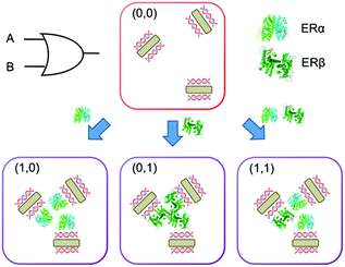
The mechanism of this multi-logic gate platform relies on the binding of estrogen receptors (ERs) to dsDNA adsorbed on gold nanorods (Scheme 1). ERs are a group of transcription factors activated by estrogen22 (i.e. steroid hormone that regulates several functions including the development of the reproductive system and maintenance of the bone structure). ER's action involves binding to specific DNA sequences, called estrogen receptor elements (EREs), that trigger the estrogen biological response.23 The dsDNA used in this work is 35 base-pair long and contains the ERE consensus sequence (GGTCAnnnTGACC, where n are spacer nucleotides), which provides binding specificity for ERs (i.e. ERα and ERβ). AuNRs with an aspect ratio of 4.1 were synthesized by a seed-mediated method (Fig. S1†).24 Hexadecyltrimethylammonium bromide was used as the surfactant, which provides positive charges to the surface of nanorods. We recently proved that when positively charged AuNRs are mixed with negatively charged dsDNA, the nucleic acid molecules are adsorbed on the nanoparticle surface (dsDNA-AuNR), changing the electric potential of the particles.25 The variation of the surface charge of the rods triggers the nanoparticle aggregation at lower dsDNA concentrations and disaggregation at higher concentrations.
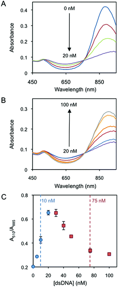
Fig. 1A presents the red shift of the AuNR longitudinal localised surface plasmon resonance (L-LSPR) band by the addition of dsDNA from 0 to 20 nM (Au0 concentration of 257 μM). Interestingly, a further increase of dsDNA, i.e. from 20 to 100 nM, blue shifts the L-LSPR band (Fig. 1B). In a plot of the absorbance ratio at the two plasmon band maxima wavelengths (A510/A885) versus dsDNA concentration (Fig. 1C), the lower (blue circles) and the higher (red squares) concentration regimes are clearly observed. Dynamic light scattering characterization (DLS, Fig. S2†) confirms the initial rod aggregation and later disaggregation, which accounts for the increase and decrease of A510/A885 values in Fig. 1C, respectively. DLS data show the increase of the rod hydrodynamic diameter from 55 nm up to 3803 nm after the addition of 20 nM dsDNA. The initial dispersity, measured by the initial particle size, is almost fully recovered at 100 nM dsDNA, where the hydrodynamic diameter decreases to 64 nm. The change of the AuNR's surface charge as a driving force behind the two-concentration regime behaviour25 is further verified by zeta potential analysis (Fig. S2†). AuNRs are initially positively charged (30.4 mV). The addition of dsDNA starts neutralizing the surface charge by electrostatic screening, decreasing the electrostatic repulsion among the particles. This induces nanorod aggregation, which reaches its maximum when the surface charge is neutralized at around 20 nM dsDNA. Further additions of dsDNA induce a charge reversal and increase of the negative charge, which restores a part of the electrostatic repulsion among the particles and disassembles them, reaching a zeta potential of −22.6 mV at 100 nM dsDNA.
Two human ER subtypes (i.e. ERα and ERβ) and one non-ERE-binding protein (i.e. lysozyme) are used in the logic system. ERα and ERβ have an isoelectric point (pI) of 8.3 and 8.8, respectively,26 and they are sold and stored in Tris 50 mM buffer (pH 8 and 9, respectively). When 50 mM (pH 8) Tris without ERs is added to the dsDNA-AuNR solutions, the nanoparticles slightly aggregate over time (Fig. S3†). After an incubation of 40 min, the absorbance ratios are mostly stable, indicating that no further aggregation significantly occurs due to the buffer. Thus, incubation times of 40 min are chosen for all protein-binding experiments to equalize the buffer effects. The binding of ERα to dsDNA-AuNR is initially studied. Due to the different electrokinetic behaviour of dsDNA-AuNR at lower and higher dsDNA concentration regimes, the ERα binding is studied at two DNA concentrations of 10 nM (lower concentration regime) and 75 nM (higher concentration regime). Fig. 2A and B present increasing A510/A885 (increased aggregation) upon ERα binding at the respective dsDNA concentrations. Both figures show that the ERα binds to the ERE-containing dsDNA with a stoichiometry of 2 to 1, i.e. A510/A885 reaches saturation at 2![[thin space (1/6-em)]](https://www.rsc.org/images/entities/char_2009.gif) :
:![[thin space (1/6-em)]](https://www.rsc.org/images/entities/char_2009.gif) 1 of the ERα:dsDNA concentration ratio. This is in agreement with the previously published literature that reports ERα binding to ERE as a dimer.27 The proper binding stoichiometry and the negligible affinity of ERα for control DNA molecules, where the ERE binding site is scrambled,28,29 support the fact that ERα interacts with DNA through sequence-specific binding, inducing AuNR aggregation. We hypothesize that the aggregation is driven by the interprotein interactions. At pH close to the protein's pI (solutions pH ∼ 8.0), the van der Waals and dipole–dipole attractive forces dominate over the charge–charge electrostatic repulsion forces (i.e. the protein's charge is almost neutralised at pH near their pI).30 Therefore, proteins tend to aggregate at these pH values, driving the aggregation of the nanoparticles bound to them. It is worth mentioning that several studies have reported that the interprotein interactions between ERα and other transcription factors are strong and play a key role in the ERα gene regulation.31–33
1 of the ERα:dsDNA concentration ratio. This is in agreement with the previously published literature that reports ERα binding to ERE as a dimer.27 The proper binding stoichiometry and the negligible affinity of ERα for control DNA molecules, where the ERE binding site is scrambled,28,29 support the fact that ERα interacts with DNA through sequence-specific binding, inducing AuNR aggregation. We hypothesize that the aggregation is driven by the interprotein interactions. At pH close to the protein's pI (solutions pH ∼ 8.0), the van der Waals and dipole–dipole attractive forces dominate over the charge–charge electrostatic repulsion forces (i.e. the protein's charge is almost neutralised at pH near their pI).30 Therefore, proteins tend to aggregate at these pH values, driving the aggregation of the nanoparticles bound to them. It is worth mentioning that several studies have reported that the interprotein interactions between ERα and other transcription factors are strong and play a key role in the ERα gene regulation.31–33
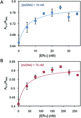 | ||
| Fig. 2 AuNR absorbance intensity ratio at 510 and 885 nm as a function of ERα concentration at (A) 10 and (B) 75 nM dsDNA. | ||
Even though the DNA-binding domains of ERα and ERβ are highly conserved (96% identity),34 their binding behaviour to ERE presents a significant difference. Fig. S4† shows the plots of the binding curve of ERβ to ERE-containing dsDNA on AuNRs at pH ∼ 8.5, using the A510/A885 ratio as the binding signal. The transcription factor induces the aggregation of dsDNA-AuNR as previously observed for ERα, i.e. increasing the A510/A885 ratio. Nevertheless the stoichiometry between ERβ and ERE is approximately 4 to 1. This observation is in agreement with previous reports, which studied the ERβ–ERE binding by surface plasmon resonance spectroscopy.35
To further affirm the role of sequence-specific protein–DNA binding, a non-ERE-binding protein, lysozyme, is used. Fig. S5A and S5B† show the plot of the A510/A885 variation versus lysozyme concentration at 10 nM and 75 nM dsDNA, respectively, as carried out for ERα experiments. At 10 nM dsDNA, the addition of lysozyme barely changes the A510/A885 (Fig. S5A†). We hypothesize that dsDNA-AuNR and lysozyme electrostatically repel each other because of their positive charges (i.e. lysozyme presents a pI of 11.2![[thin space (1/6-em)]](https://www.rsc.org/images/entities/char_2009.gif) 36 and it is positively charged at the pH ∼ 8.0 of this study). On the other hand, a moderate increase of A510/A885 (moderate aggregation increase) upon increase in the lysozyme concentration is observed at 75 nM (Fig. S5B†). This is because dsDNA-AuNRs are negatively charged at 75 nM and the electrostatic interaction between dsDNA-AuNRs and lysozyme is favoured.
36 and it is positively charged at the pH ∼ 8.0 of this study). On the other hand, a moderate increase of A510/A885 (moderate aggregation increase) upon increase in the lysozyme concentration is observed at 75 nM (Fig. S5B†). This is because dsDNA-AuNRs are negatively charged at 75 nM and the electrostatic interaction between dsDNA-AuNRs and lysozyme is favoured.
Interestingly, ERs (sequence-specific binding) and lysozyme (electrostatic interactions) present different nanoparticle aggregation behaviours, which are more distinguishable at low dsDNA concentrations. Therefore, the lower dsDNA concentration regime is exploited to build the platform capable of performing logic operations at the nanoscale.
We build logic gates by adding proteins or dsDNA (logic inputs) into a base solution consisting of AuNR (Au0 concentration of 257 μM) and dsDNA of 10 nM (leading to dispersed AuNRs) or 25 nM (leading to aggregated AuNRs). The logic values of the inputs are 0 and 1, which are defined as the absence and the presence of the input in solution, respectively. The outputs are read by measuring the variation in the A510/A880 ratio, where the logic values 0 and 1 are experimentally established as 0.65 and 0.75, respectively. The amount of input added into the solutions was experimentally optimized, so that the output signals are coherent in all the logic gates. First, the logic gate OR is built (Fig. 3A). The base solution contains AuNRs and dsDNA (10 nM), and the two inputs are ERα (20 nM) and ERβ (30 nM). Both inputs induce a similar level of aggregation when separately added (0/1 and 1/0). Interestingly, when both ERs are added at the same time (1/1), a similar level of aggregation is obtained, rather than a higher one. This is most likely because the amount of ERE-containing dsDNA is the limiting factor. Thus, the excess of ERs does not bind to the dsDNA and it is left in solution without interacting with the nanoparticles. Next, the NOT gate is designed (Fig. 3B). It is a 1-input 1-output gate that performs logic negation. The base solution contains AuNRs and 25 nM dsDNA, which aggregates the nanoparticles (0/0). When more dsDNA (additional 15 nM) is added as an input in a second step, the nanoparticles disaggregate (1/1). OR and NOT are basic operations and all the rest can be obtained by combining them (e.g. through cascade reactions21). Nevertheless, it is worth mentioning that our system allows the direct building of derivative operations without the need for combining basic operations. First, the A IMPLY B gate is developed by using a base solution with AuNRs and 25 nM dsDNA (Fig. 3C). The two inputs are dsDNA (additional 15 nM) and ERβ (30 nM). In the initial state (0/0), the nanoparticles are aggregated. When more dsDNA is added (1/0), the new dsDNA triggers AuNR disassembly. The single addition of ERβ (0/1) does not change the aggregation state of the nanoparticles because they are already aggregated. The addition of both inputs (1/1) results in AuNR aggregation, since dsDNA's disassemble capacity is compensated by ERβ aggregating behaviour. Next, the BUFFER logic gate is demonstrated. A base solution made of AuNRs and 10 nM dsDNA, and one input (20 nM ERα) are required (Fig. 3D). The mechanism of this gate is based on the further aggregation of dsDNA-AuNR induced by ERα (1). The TRUE logic gate can also be obtained. This is constructed by using a base solution of AuNRs and 25 nM dsDNA (Fig. 3E). The two inputs are ERα (20 nM) and ERβ (30 nM). Since the nanoparticles are already aggregated in the initial state (0/0), the addition of ERs does not significantly change the aggregation state of the system. Lastly, the FALSE gate is built (Fig. 3F). The base solution contains AuNRs and 10 nM dsDNA, and the inputs are lysozyme (20 nM) and dsDNA (additional 27 nM). In the initial state, the AuNRs are dispersed (0/0). Lysozyme does not interact with ERE-containing dsDNA, and its addition (1/0) does not affect the aggregation state. The addition of extra 27 nM dsDNA keeps the nanoparticles disaggregated (0/1 and 1/1). Based on the previous zeta potential results, we hypothesize that the amount of dsDNA in solution is enough to induce a nanoparticle charge reversal and provide enough electrostatic repulsion to disaggregate the AuNRs. It is worth mentioning that even though this is a multi-component system, the sequence-specific binding is essential for building four of the six logic gates (i.e. OR, A IMPLY B, BUFFER and TRUE). A limited number of logic operations (i.e. NOT and FALSE) can be performed by using only dsDNA and/or non-specific binding protein as inputs.
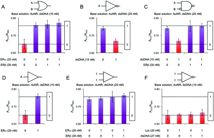 | ||
| Fig. 3 AuNR absorbance ratio intensities at 510 and 885 nm as a function of different inputs in (A) OR, (B) NOT, (C) A IMPLY B, (D) BUFFER, (E) TRUE and (F) FALSE logic gates. | ||
Finally, the results from the logic gate experiments are statistically assessed, rendering two conclusions: (1) All the A510/A885 outputs are successfully labelled as logic 0 or 1 values, since they are not statistically different from one of the two reference values, i.e. 0.65 and 0.75, respectively (p > 0.05, Table S1); (2) the values for logic 0 are statistically different and clearly distinguishable from the values for logic 1 (p < 0.05, Table S2; Cohen's d > 3.5, Table S3†).
In summary, we have developed a plasmonic hybrid system made of AuNR and ERE-containing dsDNA capable of tracking the binding of ERs (i.e. ERα and ERβ) to their response element. The system is sensitive enough to distinguish between protein isomorphs. The mechanism is based on the interprotein interactions among ERs, which are bound to dsDNA on the surface of AuNRs under sequence recognition, and trigger nanoparticle's aggregation. The combination of proteins, ERE-containing dsDNA, AuNRs and the interactions among them allow expanding the system to a plasmonic logic gate platform, becoming the first system that performs logic operations by mimicking transcription factor's gene regulation. This versatile system is able to perform 6 different logic operations (i.e. OR, NOT, A IMPLY B, BUFFER, TRUE and FALSE) by changing the design set-up. This overcomes one of the main limitations of traditional nanoscale logic gates, which are just able to perform few logic operations with the same platform. Furthermore, this system is conceptually simple, easy-to-use and does not require complex surface modifications, toxic ligands or separation/purification steps. Based on these results, two different directions can be envisioned in order to expand the performance of the multi-logic gate platform: (1) the combination of different logic gates through cascade reactions, which could result in more complex logic operations, such as the combination of OR and NOT to obtain the universal gate NOR (Scheme 2). (2) It is expected that the combination of this nanomaterial-based method with microfluidic technologies could result in a lab-on-chip device capable of resetting the system for several consecutive operations. Lastly, these new insights into the spatial and temporal control over nanomaterial assembly by transcription factors can be the first steps for other nanoscale technologies, such as transcription factor-mediated smart drug release.
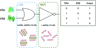 | ||
| Scheme 2 Schematic illustration of a possible cascade reaction based on the individual logic gates developed in this work. OR and NOT gates are combined to yield the universal NOR gate. | ||
Acknowledgements
Roger M. Pallares thanks UCL and A*STAR for his PhD studentship. Xiaodi Su thanks A*STAR JCO funding 14302FG096. Nguyễn T. K. Thanh thanks the Royal Society for her Royal Society University Research Fellowship and EPSRC (Grant no. EP/M015157/1) the financial support.Notes and references
- A. P. de Silva and S. Uchiyama, Nat. Nanotechnol., 2007, 2, 399–410 CrossRef CAS PubMed.
- A. P. De Silva and N. D. McClenaghan, Chem. – Eur. J., 2004, 10, 574–586 CrossRef PubMed.
- U. Pischel, Angew. Chem., Int. Ed., 2007, 46, 4026–4040 CrossRef CAS PubMed.
- X. L. Xu, F. W. Lin, W. Xu, J. Wu and Z. K. Xu, Chem. – Eur. J., 2015, 21, 984–987 CrossRef CAS PubMed.
- F. Pu, E. Ju, J. Ren and X. Qu, Adv. Mater., 2014, 26, 1111–1117 CrossRef CAS PubMed.
- A. Saghatelian, N. H. Völcker, K. M. Guckian, V. S. Y. Lin and M. R. Ghadiri, J. Am. Chem. Soc., 2003, 125, 346–347 CrossRef CAS.
- Y. He and H. Cui, Chem. – Eur. J., 2013, 19, 13584–13589 CrossRef CAS PubMed.
- X. Liu, R. Aizen, R. Freeman, O. Yehezkeli and I. Willner, ACS Nano, 2012, 6, 3553–3563 CrossRef CAS PubMed.
- R. Gui, H. Jin, Z. Wang, F. Zhang, J. Xia, M. Yang, S. Bi and Y. Xia, Nanoscale, 2015, 7, 8289–8293 RSC.
- B. M. G. Janssen, M. Van Rosmalen, L. Van Beek and M. Merkx, Angew. Chem., Int. Ed., 2015, 54, 2530–2533 CrossRef CAS PubMed.
- A. Ogawa and M. Maeda, Chem. Commun., 2009, 4666–4668 RSC.
- D. Liu, W. Chen, K. Sun, K. Deng, W. Zhang, Z. Wang and X. Jiang, Angew. Chem., Int. Ed., 2011, 50, 4103–4107 CrossRef CAS PubMed.
- X. Xu, J. Zhang, F. Yang and X. Yang, Chem. Commun., 2011, 47, 9435–9437 RSC.
- J. Du, S. Yin, L. Jiang, B. Ma and X. Chen, Chem. Commun., 2012, 4196–4198 Search PubMed.
- Y. Xianyu, Z. Wang, J. Sun, X. Wang and X. Jiang, Small, 2014, 10, 4833–4838 CrossRef CAS PubMed.
- S. K. Ghosh and T. Pal, Chem. Rev., 2007, 107, 4797–4862 CrossRef CAS PubMed.
- Y. Lu and J. Liu, Acc. Chem. Res., 2007, 40, 315–323 CrossRef CAS PubMed.
- Y. Zhang, W. Liu, W. Zhang, S. Yu, X. Yue, W. Zhu, D. Zhang, Y. Wang and J. Wang, Biosens. Bioelectron., 2015, 72, 218–224 CrossRef PubMed.
- R. M. Zadegan, M. D. E. Jepsen, L. L. Hildebrandt, V. Birkedal and J. Kjems, Small, 2015, 11, 1811–1817 CrossRef CAS PubMed.
- R. Orbach, B. Willner and I. Willner, Chem. Commun., 2015, 51, 4144–4160 RSC.
- Y. Li, W. Li, K.-Y. He, P. Li, Y. Huang, Z. Nie and S.-Z. Yao, Nanoscale, 2016, 8, 8591–8599 RSC.
- V. Kumar, S. Green, G. Stack, M. Berry, J. R. Jin and P. Chambon, Cell, 1987, 51, 941–951 CrossRef CAS PubMed.
- C. M. Klinge, Nucleic Acids Res., 2001, 29, 2905–2919 CrossRef CAS PubMed.
- R. M. Pallares, X. Su, S. H. Lim and N. T. K. Thanh, J. Mater. Chem. C, 2016, 4, 53–61 RSC.
- R. M. Pallares, S. L. Kong, T. H. Ru, N. T. K. Thanh, Y. Lu and X. Su, Chem. Commun., 2015, 51, 14524–14527 RSC.
- S. Yamashita and Y. Okada, J. Histochem. Cytochem., 2005, 53, 13–21 CrossRef CAS PubMed.
- S. Lukman, K. M. M. Aung, J. Liu, B. Liu and X. Su, ACS Appl. Mater. Interfaces, 2013, 5, 12725–12734 CAS.
- S. J. Neo, X. Su and J. S. Thomsen, Anal. Chem., 2009, 81, 3344–3349 CrossRef CAS PubMed.
- W. Y. X. Peh, E. Reimhult, H. F. Teh, J. S. Thomsen and X. Su, Biophys. J., 2007, 92, 4415–4423 CrossRef CAS PubMed.
- O. D. Velev, E. W. Kaler and A. M. Lenhoff, Biophys. J., 1998, 75, 2682–2697 CrossRef CAS PubMed.
- J. R. Schultz, L. N. Petz and A. M. Nardulli, Mol. Cell. Endocrinol., 2003, 201, 165–175 CrossRef CAS PubMed.
- L. N. Petz, Y. S. Ziegler, J. R. Schultz, H. Kim, J. K. Kemper and A. M. Nardulli, J. Steroid Biochem. Mol. Biol., 2004, 88, 113–122 CrossRef CAS PubMed.
- M. Jakacka, M. Ito, J. Weiss, P. Y. Chien, B. D. Gehm and J. L. Jameson, J. Biol. Chem., 2001, 276, 13615–13621 CAS.
- S. Mosselman, J. Polman and R. Dijkema, FEBS Lett., 1996, 392, 49–53 CrossRef CAS PubMed.
- X. Su, C. Y. Lin, S. J. O'Shea, H. F. Teh, W. Y. X. Peh and J. S. Thomsen, Anal. Chem., 2006, 78, 5552–5558 CrossRef CAS PubMed.
- Z. Cai, G. Chen, X. Huang and M. Ma, Sens. Actuators, B, 2011, 157, 368–373 CrossRef CAS.
Footnote |
| † Electronic supplementary information (ESI) available. See DOI: 10.1039/c6nr07569j |
| This journal is © The Royal Society of Chemistry 2016 |

