
 Open Access Article
 This Open Access Article is licensed under a
 Creative Commons Attribution 3.0 Unported Licence
Two-dimensional core–shell donor–acceptor assemblies at metal–organic interfaces promoted by surface-mediated charge transfer†
A.
Della Pia
a,
M.
Riello
b,
D.
Stassen
c,
T. S.
Jones
a,
D.
Bonifazi
*cd,
A.
De Vita
*be and
G.
Costantini
*a
aDepartment of Chemistry, University of Warwick, Gibbet Hill Road, Coventry CV4 7AL, UK. E-mail: g.costantini@warwick.ac.uk
bDepartment of Physics, King's College London, Strand, London WC2R 2LS, UK. E-mail: alessandro.de_vita@kcl.ac.uk
cNamur Research College (NARC) and Department of Chemistry, University of Namur (UNamur), BE B-5000, Belgium. E-mail: bonifazid@cardiff.ac.uk
dSchool of Chemistry, Cardiff University, Park Place, Cardiff, CF10 3AT, UK
eDepartment of Engineering and Architecture, University of Trieste, I-34127 Trieste, Italy
First published on 2nd November 2016
Abstract
Organic charge transfer (CT) complexes obtained by combining molecular electron donors and acceptors have attracted much interest due to their potential applications in organic opto-electronic devices. In order to work, these systems must have an electronic matching – the highest occupied molecular orbital (HOMO) of the donor must couple with the lowest unoccupied molecular orbital (LUMO) of the acceptor – and a structural matching, so as to allow direct intermolecular CT. Here it is shown that, when molecules are adsorbed on a metal surface, novel molecular organizations driven by surface-mediated CT can appear that have no counterpart in condensed phase non-covalent assemblies of donor and acceptor molecules. By means of scanning tunneling microscopy and spectroscopy it is demonstrated that the electronic and self-assembly properties of an electron acceptor molecule can change dramatically in the presence of an additional molecular species with marked electron donor character, leading to the formation of unprecedented core–shell assemblies. DFT and classical force-field simulations reveal that this is a consequence of charge transfer from the donor to the acceptor molecules mediated by the metallic substrate.
Introduction
Engineering any electron donor–acceptor (D–A) system, regardless of whether covalent or non-covalent, requires the combination of electron-rich (i.e., low ionization energy) molecules with electron-deficient (i.e., high electron affinity) counterparts to form charge-transfer (CT) complexes. These systems have attracted significant research efforts1 because they display a metallic behavior,2 high-temperature superconductivity3 or can be used as materials for ambipolar semiconductors4 and artificial light-conversion applications.5–9 More recently, a number of other interesting properties stemming directly from CT interactions in D–A systems have been reported, including thermoelectricity, photoconductivity, ferroelectricity, magnetoconductance, and field emission (ref. 1 and references therein). Depending on the structural and electronic properties of the D and A molecular modules, different types of non-covalent assemblies have been observed, each of them related to specific optoelectronic properties. In the condensed phase, like solid state or in liquid crystals, various supramolecular structures can be obtained:10–12 a vertical alternating stacking with a two-dimensional (2D) checkerboard arrangement (Fig. 1(a)), a homomolecular columnar arrangement patterned as a 2D checkerboard array (Fig. 1(b)), a homomolecular columnar arrangement patterned as a 2D-striped array (Fig. 1(c)), a phase-segregated homomolecular columnar arrangement (Fig. 1(d)), and a layer-by-layer arrangement with a vertical alternating stacking organization (Fig. 1(e)). | ||
| Fig. 1 Schematic representation of: (a)–(e) the most common molecular organizations of non-covalent donor–acceptor assemblies in condensed phases; (f) the novel core–shell organization motif discovered in this work. Red: acceptor molecule (A); blue: donor molecule (D). | ||
Most of the promising applications of D–A systems are in cheap, flexible and portable opto-electronics, including the production of organic ferroelectric devices, field-emission transistors and artificial photosynthetic systems.13–22 For these applications, the D–A materials are deposited from a liquid solution or by thermal vapor deposition as thin films onto a conductive electrode,23–30 resulting in organic-electrode interfaces that can be highly complex, though crucial for the device performances. On the other hand, the development of D–A architectures in thin film devices is frequently based on the simplifying assumption that the optoelectronic properties of the organic materials are preserved even after surface deposition. This assumption often neglects the fact that the adsorption of organic molecules onto a solid electrode can significantly modify the relative energies of the relevant molecular electronic orbitals, dramatically affecting the material's optoelectronic properties and the intermolecular bonding at the interface. As consequence, both the electronic structure and the molecular organization of functional organic thin films can be significantly different from their bulk counterparts, resulting in significant variations with respect to the expected device performance. In spite of this, although several studies have been reported on the perturbation of the electronic structure of single molecules after surface adsorption,31–36 the effect of solid surfaces on the electronic properties of interfacial D–A systems has received much less attention.37–41 While these perturbations are often seen as challenges to be overcome, they can also represent an opportunity, as unprecedented D–A assemblies can be obtained as a result of processes occurring exclusively at metal–organic interfaces.
In this work, we investigated the surface co-deposition of electron donor 1,3,6,8-tetrakis(3,5-di-tert-butylphenyl)pyrene (TBP)33 and electron acceptor 7,7,8,8-tetracyanoquinodimethane (TCNQ),42,43 two good molecular candidates (Scheme 1) for forming D–A supramolecular networks due to their complementary electronic properties (a relatively small ionization potential and large electron affinity for TBP and TCNQ, respectively). We find that when these molecules are deposited on the highly polarizable and high work function Au(111) substrate, the surface acts as a mediator for the energy level alignment between the D and A molecules to allow intermolecular CT between the two species. This exquisitely interfacial phenomenon drives the formation of an unprecedented assembly of non-covalent D–A systems where the molecular species are organized in a core–shell architecture44 with the TBP donors mono-molecularly surrounding clusters of TCNQ acceptors (Fig. 1(f)).
 | ||
| Scheme 1 Chemical structures of the molecular donor and acceptor building blocks investigated in this work: TBP and TCNQ, respectively. | ||
Results
When co-deposited on the Au(111) surface, TBP and TCNQ phase separate (Fig. 2(a)), displaying a behavior qualitatively similar to what is observed in the solid state. A distinctive characteristic of the two-dimensional assembly is however the appearance of hybrid clusters displaying a core–shell structure, in which an island of TCNQ is surrounded by a peripheral monomolecular rim of TBP molecules (Fig. 2(b)). Whereas all TCNQ molecules assemble in these clusters, the excess TBP molecules form homomolecular islands, the organization and structure of which follow the same herringbone arrangement observed when only TBP is deposited on Au(111)33 (Fig. 3(a)). These TBP islands result from a delicate interplay of attractive vdW forces and repulsive electrostatic interactions, the latter caused by interfacial dipoles induced by reversible integer CT from the TBP molecules to the substrate.33 | ||
Fig. 2 Scanning tunneling microscopy (STM) images of the assembly resulting from the co-deposition of TBP and TCNQ (≈ 1![[thin space (1/6-em)]](https://www.rsc.org/images/entities/char_2009.gif) :3 ratio) on the Au(111) substrate. (a) Large view demonstrating the core–shell arrangement of TBP and TCNQ molecules. (b) Close up image of the core–shell assembly where a β-TCNQ cluster is surrounded by a monomolecular rim of TBP molecules. Molecular models of TCNQ and TBP are superposed to the image in (b) for clarity. :3 ratio) on the Au(111) substrate. (a) Large view demonstrating the core–shell arrangement of TBP and TCNQ molecules. (b) Close up image of the core–shell assembly where a β-TCNQ cluster is surrounded by a monomolecular rim of TBP molecules. Molecular models of TCNQ and TBP are superposed to the image in (b) for clarity. | ||
 | ||
| Fig. 3 STM images showing the assembly resulting from the sole deposition of (a) TBP and (b) TCNQ molecules on a Au(111) surface. The insets show enlarged areas in the same regions highlighting the molecular assemblies with superposed molecular models. | ||
By contrast, the arrangement of the TCNQ molecules and the size of the islands they form are remarkably different to the case of pure TCNQ on Au(111). As reported by Pascual and co-workers,45 when TCNQ is deposited on its own on Au(111), it forms an extended H-bonded network (Fig. 3(b)), referred to as α-TCNQ phase in the following. The molecules adsorb in their neutral charge state45–47 and arrange in a typical brickwork manner, maximizing the number of H-bonds between the nitrile groups and the aryl hydrogens. However, in the presence of TBP, TCNQ molecules cluster in the core–shell assemblies (with typical lateral extension <250 nm2) displaying a different organization (referred to as β-TCNQ in the following), characterized by a parallel molecular alignment in two directions, which we dub “parallel arrangement” (Fig. 2(b)).
Since the adjacent electron-rich nitrile groups would cause large electrostatic repulsions, the β-TCNQ is not expected to be an energy minimum configuration for a pure TCNQ phase. Consistently, DFT calculations performed on a gas-phase monolayer of TCNQ molecules arranged in the β phase reveal that the parallel arrangement is energetically highly expensive and that the total energy of the system is significantly reduced by reverting to the hydrogen-bonded brickwork network (for details see ESI, section 2.1†). On the other hand, the difference between the α- and β-phases, observed for TCNQ molecules in the absence or presence of TBP, might be indicative of a different charge state. Voltage dependent imaging and local spectroscopy experiments were performed in order to explore this hypothesis. Firstly, scanning tunneling microscopy (STM) topographies were acquired while varying the sample bias voltage. At negative voltages – corresponding to the tunneling from occupied electronic states of the sample – α-TCNQ molecules appear as elliptic protrusions (Fig. 4(a)). Instead, at positive voltage – tunneling into empty electronic states of the sample, Fig. 4(b) – the molecules appear as two symmetric U-shaped protrusions and two circular bulges, each of which is centered on the dicyanomethylene groups, separated by a central nodal plane. The latter imaging mode has a close resemblance with the spatial distribution of the lowest unoccupied molecular orbital (LUMO) of a neutral TCNQ molecule in the gas phase, as determined by DFT (see inset in Fig. 4(b)). As a consequence, the observed voltage dependence of α-TCNQ molecules is indicative of the presence of neutral molecules weakly interacting with the substrate, as observed previously.45 STM images of β-TCNQ molecules in the core–shell assembly bear a close similarity to the LUMO spatial distribution of isolated TCNQ molecules too (Fig. 4(c)). In fact, even if their appearance is slightly different from that observed in the α phase – because of the absence of H-bonds in the core–shell assemblies (see ESI, section 2.2†) – the characteristic LUMO nodal central plane separating two elongated ellipsoidal shapes and the two circular protrusions corresponding to the dicyanomethylene moieties can still be easily recognized. The crucial difference with α-TCNQ is that the “LUMO-shaped” features are now found in the energy region corresponding to occupied electronic sample states, strongly suggesting that TCNQ is negatively charged in the β-phase of the core–shell structures. A closer inspection of the STM images of the β-assembly reveals the presence of additional circular bright protrusions between the nitrogen atoms of four adjacent TCNQ molecules (circled in black in Fig. 4(c) and (d)). These features do not appear at every position of the molecular lattice and hence cannot be linked to a particular tip imaging mode or to an electronic effect. Instead, we associate them with Au adatoms directly bound to TCNQ molecules in a metal–organic structure, which is a further indication of the anionic state of β-TCNQ molecules. Several examples have been reported in the literature where the negative charging of a molecular species on a metallic substrate is correlated to the formation of metal–organic complexes with positively charged substrate atoms (either lifted from the substrate31,34,48 or segregated from step edges as adatoms40,46,49–51), as this is an efficient way to reduce electrostatic repulsion.52
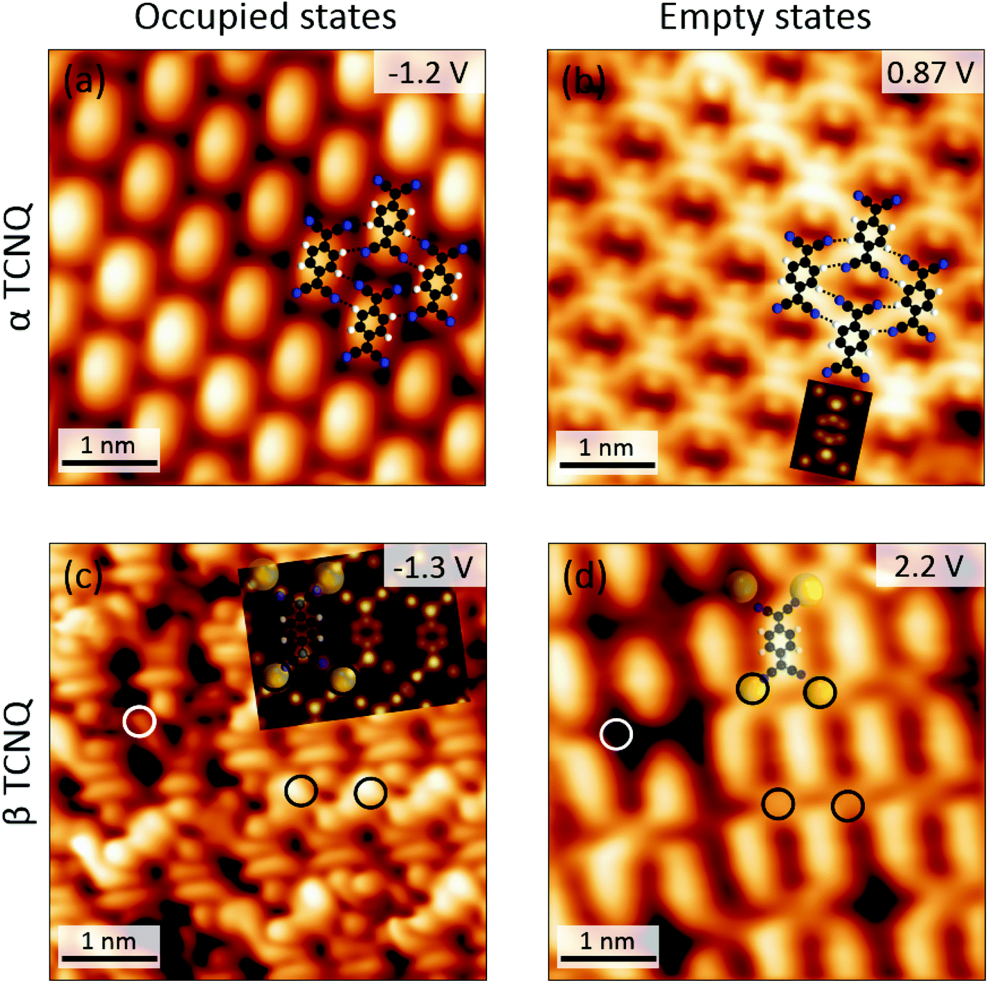 | ||
Fig. 4 Bias voltage dependent STM images of α- and β-TCNQ molecules on Au(111). The DFT calculated spatial distribution of the LUMO of a neutral TCNQ molecule in the gas phase is shown as inset in (b). C![[triple bond, length as m-dash]](https://www.rsc.org/images/entities/char_e002.gif) N⋯H–C hydrogen bonds are marked by black dashed lines in (a) and (b). The simulated constant current STM image superposed in (c) was calculated at a bias voltage of −1.3 V by using the Tersoff–Hamann approach76 based on the structure of Fig. 6(a). Au adatoms and vacancies in the β-TCNQ structure are circled in black and white, respectively, in (c) and (d). N⋯H–C hydrogen bonds are marked by black dashed lines in (a) and (b). The simulated constant current STM image superposed in (c) was calculated at a bias voltage of −1.3 V by using the Tersoff–Hamann approach76 based on the structure of Fig. 6(a). Au adatoms and vacancies in the β-TCNQ structure are circled in black and white, respectively, in (c) and (d). | ||
Further experimental evidence that β-TCNQ molecules have an occupied energy level corresponding to the gas-phase LUMO can be obtained by performing scanning tunneling spectroscopy (STS) measurements. dI/dV spectra acquired on the α phase of TCNQ exhibit two main features:45 a broad peak at positive voltage associated to the empty LUMO level and a shift of the Au(111) surface state, due to the pillow effect53 (Fig. 5(a)). In contrast, significantly different spectra are recorded on β-TCNQ molecules (Fig. 5(b)). Firstly, the Au(111) surface state is no longer visible, signaling a significant charge rearrangement at the metal–organic interface. Secondly, depending on where the spectrum is measured, different features are observed. The dI/dV spectra acquired close to the cyano group/Au adatom positions are characterized by a broad peak at −1.0 V, as can be seen in Fig. 5(b) (red line). A small peak around +0.9 V is instead observed when measuring a spectrum over the central ring of a β-TCNQ molecule (Fig. 5(b), blue line). We identify the peak observed at −1.0 V as a metal–organic state, resulting from the mixing between Au adatom states and the LUMO of the TCNQ molecule (see ESI, section 2.3†). The peak at positive voltage, localized on the aromatic core, is instead associated to the LUMO+1 derived resonance of TCNQ, as evidenced by plotting the relevant gas phase DFT molecular orbital (see ESI, section 2.1†).
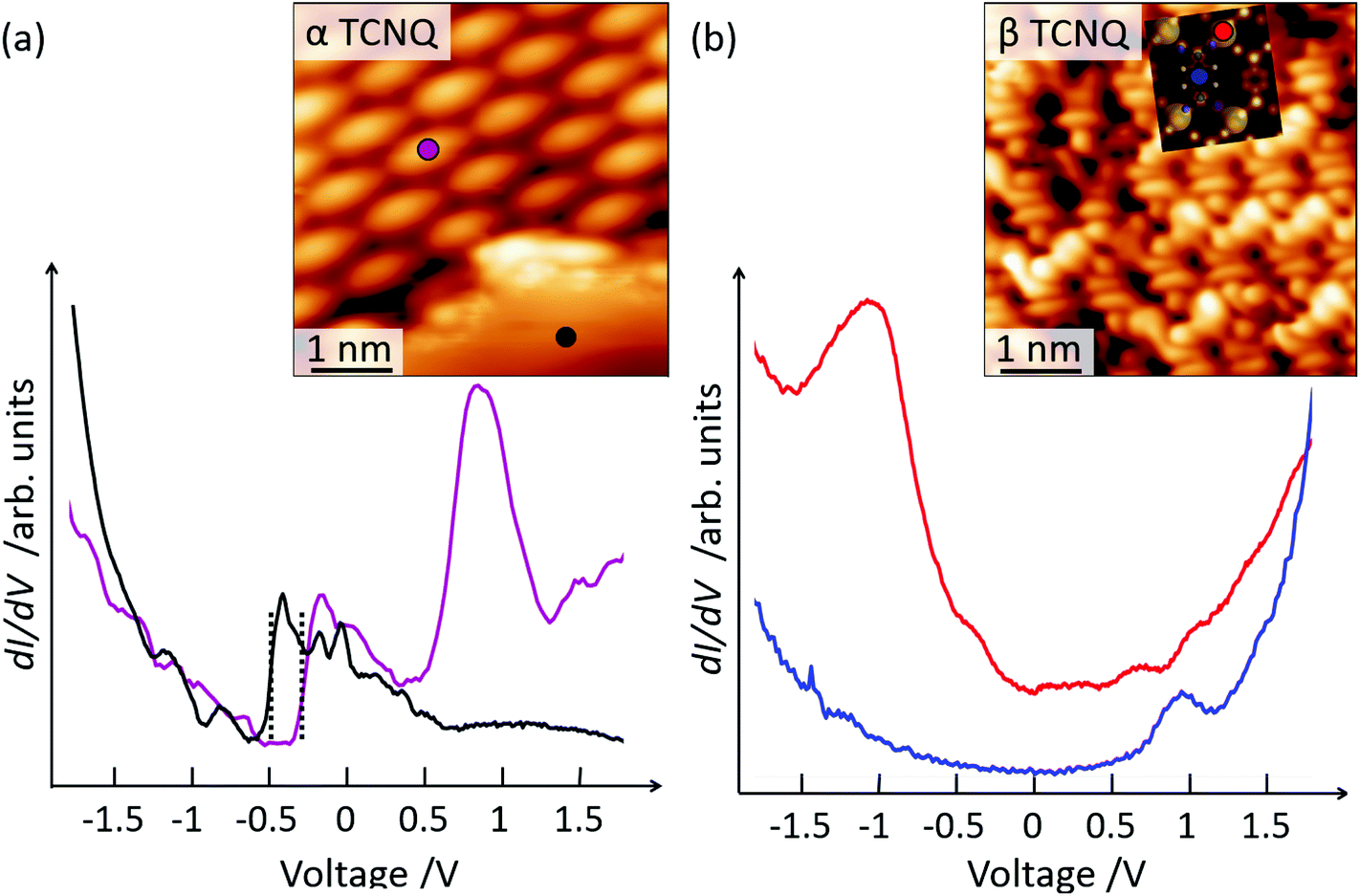 | ||
| Fig. 5 dI/dV spectroscopy on (a) α-TCNQ and (b) β-TCNQ molecules. The positions where the measurements were acquired are identified by filled circles in the STM images (shown as insets), with the same color of the corresponding spectra. A spectrum on clean Au(111) is shown as reference in (a) (black curve). The onset of the Au(111) surface state is indicated by dotted lines in (a). | ||
Overall, a number of observations in our experiments point toward charging of β-TCNQ molecules: the parallel assembly of β-TCNQ molecules (energetically unfavorable for neutral species); the LUMO-shaped filled states produced by STM imagining; the presence of a LUMO-derived peak in the occupied states STS spectroscopy; the formation of a metal–organic structure consistent with CT. However, the charging of TCNQ molecules on Au(111) is surprising because CT has so far only been reported for TCNQ deposited on less noble (i.e. smaller work function) metal surfaces such as Ag(111),46 Ag(100),54 Cu(111),55,56 Cu(100)31 and Ni(111)57), while STM, STS,45 and X-ray and ultraviolet photoelectron spectroscopy measurements46 clearly demonstrate that TCNQ molecules remain neutral when absorbed on Au(111). This implies that TCNQ charging and assembly in the β phase must be a direct effect of the presence of the surrounding TBP (see Discussion section).
DFT calculations were employed to rationalize the mechanism behind the CT phenomena and the formation of the Au-TCNQ metal–organic structures. To this aim we considered a full monolayer of β-arranged TCNQ molecules (see ESI, section 2.2†) and incorporated one additional Au adatom for each TCNQ molecule, located in a hollow site of the unreconstructed Au(111) substrate. A stable metal–organic structure formed, as shown in Fig. 6(a) (see ESI, section 2.2,† for details). The presence of the Au adatoms stabilizes the β-assembly, otherwise forbidden due to the proximity of the electronegative N atoms, which are instead mutually screened by the adatoms. Only two N atoms coordinate to each Au adatom bending downwards with respect to the molecular core (≈ 0.7 Å) (Fig. 6(a)). A similar distortion was previously reported for TCNQ and similar acceptor molecules31,32,58,59 and was correlated with a re-aromatization of the molecular core induced by charge rearrangement at the metal–organic interface. Hence, the bent adsorption configuration of β-TCNQ molecules provides a first element of theoretical confirmation that these molecules are charged. Moreover, the occurrence of CT can be directly investigated by examining the TCNQ projected density of states (pDOS, see ESI, section 2.3†). Calculations reveal that the electron state corresponding to the gas phase highest occupied molecular orbital (HOMO) is located well below the Fermi level of the substrate at −1.1 eV, while the energy of the gas-phase LUMO orbital aligns to the Fermi level, indicating a partial occupation and hence molecular charging. Evidence of charge donation from Au adatoms to TCNQ in the contour plot of the electron density displacement pattern Δρ(r) reported in Fig. 6(b) (see also ESI, section 2.3†) further confirms the picture above. Significant charge depletion (blue areas) is observed at the bridging Au–N coordination sites while electron density accumulation (red areas) is observed to occur following the TCNQ LUMO lobes pattern.
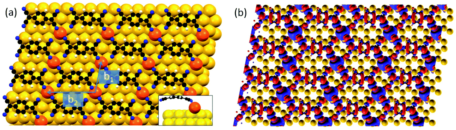 | ||
| Fig. 6 (a) Top view of the metal–organic structure formed by TCNQ molecules and Au adatoms on Au(111) calculated by DFT. The latter are colored in orange while the substrate atoms are yellow. The side view of a single TCNQ molecule bound to a gold adatom is shown as an inset, displaying the molecular bending. (b) Spatially resolved Δρ(r) isosurface (±0.004 bohr−1) for the metal–organic structure shown in (a). Red and blue areas indicate charge enrichment and depletion, respectively. | ||
Discussion
Our theoretical and experimental results reveal that TCNQ becomes charged on Au(111) due to the presence of TBP, which drives the formation of the core–shell D–A organization. The molecular assembly and the STM bias voltage dependence reported in Fig. 4(c) and (d) are remarkably similar to what observed on the same substrate for the fluorinated analogue of TCNQ, namely F4-TCNQ (2,3,5,6-tetrafluoro-7,7,8,8-tetracyanoquinodimethane).49,60 It should however be noted that while TCNQ is not an acceptor on Au(111), F4-TCNQ does accept electrons from Au(111)58,61 since the electron-withdrawing fluorine atoms significantly increase its electron affinity with respect to TCNQ. Here therefore we find that, if (and only if) TCNQ is co-deposited with an additional molecular species with marked electron donor character (TBP), it behaves in an essentially identical manner to its fluorinated analogue. In other words, the spatial proximity of TBP molecules is sufficient (and necessary) for TCNQ to become a strong electron acceptor on Au(111). Since the TBP and TCNQ molecules are not intermixed, direct intermolecular CT as commonly observed for D–A supramolecular assemblies38–40,60,62–67 can be reasonably excluded. Rather, the negative charging of TCNQ can be explained by an exquisite interfacial phenomenon, namely a substrate-mediated CT process occurring exclusively in the presence of a donor molecule. In order to elucidate this behavior, it is important to realize that the driving force for charging an individual TCNQ molecule depends not only on the position of its frontier orbitals with respect to the substrate Fermi level, but also on the electrostatic interaction with the metallic surface and with its neighboring molecules.More specifically, two types of screening effects contribute to the net energy change caused by transferring charge to an adsorbed TCNQ molecule. The first is related to the image charge effect, which is defined as the attractive Coulomb interaction between a charged adsorbate and its mirror image in the highly polarizable metal substrate. This always represents an energy gain and therefore contributes to stabilize the charged state of any adsorbed molecule (by effectively narrowing its fundamental HOMO–LUMO gap).68 In the case of F4-TCNQ, the image charge screening alone is enough to overcome the charge extraction barrier from gold (as demonstrated by the formation of β-type metal-organic charge transfer complexes).49,60 This is not the case for the lower electron affinity TCNQ molecule, and is reflected in the exclusive formation of α islands of neutral molecules when TCNQ is deposited on its own on Au(111). However, the presence of a second molecular species with opposite charge transfer behavior, like TBP, causes a further energy gain for a negatively charged TCNQ, due to the attractive electrostatic interaction between oppositely charged molecules. The development of the β molecular phase when TBP is co-deposited with TCNQ, demonstrates that this extra energetic contribution is enough to compensate the unfavorable Au(111)/TCNQ energy level alignment, enabling interfacial charge transfer for TCNQ and making it an electron acceptor on Au(111). This second type of electrostatic correction is clearly a local effect, as it depends on the number and spatial distribution of neighboring TBP molecules. As such, depending on the TCNQ:TBP local stoichiometry, regions where neutral TCNQ molecules arrange in the brickwork α-phase coexist with β-phases composed of negatively charged TCNQ molecules.
A final point in the understanding of the observed phenomenology concerns the formation of core–shell assemblies, in which TBP molecules surround β-TCNQ islands (Fig. 2). Grand Canonical Monte Carlo (GCMC) simulations can be used to investigate this process and its dependence on CT and local electrostatic screening. We modelled the presence of two differently charged molecular species, treated as structure-less particles, by associating a dipole pointing away from the surface with particles simulating positive TBP molecules, and a smaller dipole, oriented in the opposite direction, with particles simulating negative TCNQ (the dipoles are due to the image charge polarization of the metallic substrate, see ESI, section 3†). The corresponding Hamiltonian includes an attractive short-range interaction term between nearest neighbors and a long-range term between each pair of molecules, representing the Coulomb electrostatic interaction between dipoles. Due to the presence of dipoles of opposite orientations, the long-range interactions can be either repulsive (between TBP–TBP and TCNQ–TCNQ pairs) or attractive (TCNQ–TBP pairs). The short-range coupling was considered to be stronger for interactions between homo-pairs compared to hetero-pairs (see ESI, section 3†). This parametrization is supported by the experimental observation of phase segregation into homomolecular TCNQ and TBP islands, as it is typical for assemblies of immiscible components.
In our simulations, for a relative TCNQ:TBP stoichiometry close to 3:1, the formation of core–shell assemblies composed of small TCNQ islands surrounded by a rim of TBP molecules was produced as the most stable assembly outcome (Fig. 7), in excellent agreement with the experimental observations (Fig. 2). While TCNQ and TBP molecules are negatively and positively charged, respectively, it is convenient for TBP molecules to organize peripherally around the negative TCNQ cluster. This type of structure maximizes the high metal–organic bonding energy of TCNQ–TCNQ pairs and, at the same time, minimizes the TBP–TBP electrostatic repulsion thanks to the relative proximity of a negative charge (i.e. TCNQ). Conversely, by running simulations on hypothetical systems where only one of the two species is charged or where both molecules are neutral, completely different assemblies are found (see ESI, section 3†). Our simplified model is thus able to capture the assembly behavior of a binary mixture of oppositely charged molecules and further confirms that the formation of the core–shell assemblies with D and A molecules requires both molecules to carry a net CT dipole. We note that different (co-)adsorbed molecular species, including both D and A molecules, could yield a similar assembly behavior to the one observed in the present system. We expect that the model used in this analysis could be generally applied to describe these systems, provided that detailed DFT computations were viable for these species, as needed to appropriately re-calibrate the model Hamiltonian parameters.
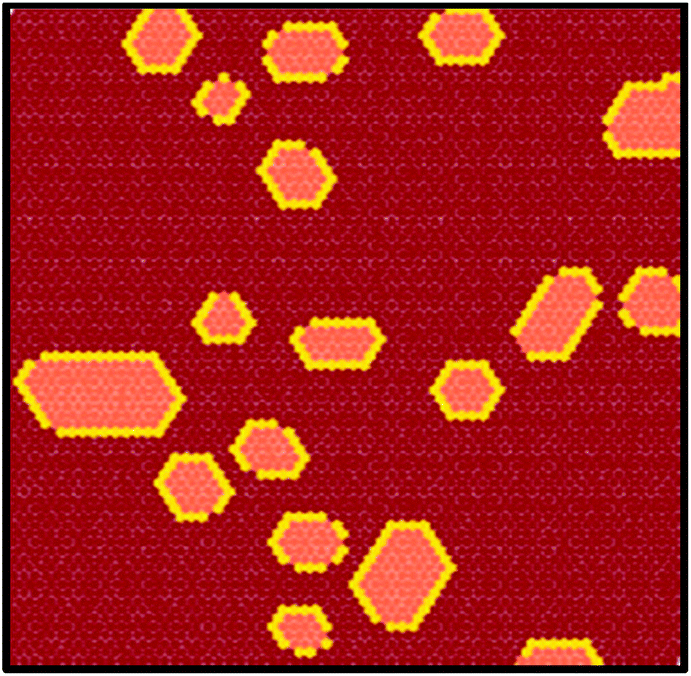 | ||
| Fig. 7 Equilibrium Monte Carlo simulation snapshot of the core–shell organization emerging from the co-deposition of oppositely charged TBP and TCNQ molecules. TBP and TCNQ molecules are represented in yellow and pink colors, respectively. | ||
Methods
Experimental methods
The experiments were performed in a commercial LT-STM system operated in ultrahigh vacuum (UHV). Multiple cycles of Ar+ sputtering (1 keV) and annealing (up to 725 K) were used to clean the Au(111) single crystal. TCNQ molecules were purchased from SIGMA Aldrich. TBP molecules were synthesized by following the procedure described in ref. 33. Previous to deposition, TBP and TCNQ molecules were degassed for several hours. Submonolayer molecular films of TCNQ and TBP molecules were grown onto the Au(111) crystal held at 300 K by using organic molecular beam deposition (OMBD). The order in the evaporation did not affect the final assembly. STM images were acquired in constant current mode at a temperature of 77 K using chemically etched tungsten tips. Typical values for the tunneling current range between a few nA and tenths of pA. The WSxM software was used to process all the STM images.69 dI/dV spectroscopy was performed at 5 K by adding a sinusoidal modulation voltage to the bias voltage via an external lock-in amplifier and recording the output of the lock-in tuned on the first harmonic. Typical parameters for the acquisition of the spectra were: stabilization current I = 1/2 nA, stabilization bias voltage V = −1.9/−2 V, frequency f and amplitude A of modulation for the lock-in amplifier: f = 1/2 KHz, A = 20 mV.Computational methods
DFT calculations and data processing were carried out with the Quantum-ESPRESSO package,70 using ultrasoft pseudopotentials71 and the PBE-GGA exchange–correlation,72 corrected by the non-local vdW-DF73 functional. Gas-phase and on-the-substrate calculations were performed with a wavefunction energy cutoff of ∼408 eV. The Brillouin zone was sampled using a 6 × 4 × 1 Monkhorst–Pack grid, while a counter dipole correction was used for all “on metal” calculations.74,75 The non-reconstructed Au(111) surface was modelled as a four-layer slab, allowing ∼12.5 Å vacuum between periodic replicas. Forces acting on the metal and molecular atoms were relaxed up to 0.05 eV Å−1 (the bottom layer of the slab being constrained to the bulk positions).
Conclusions
In this work, the low ionization potential molecule TBP (electron donor, D) was co-deposited with the high electron affinity molecule TCNQ (electron acceptor, A) on the Au(111) surface. Despite having markedly different sizes and chemical structures, the two molecular species assemble into distinctive core–shell aggregates where TCNQ islands are surrounded by a monomolecular rim of TBP molecules, an unprecedented non-covalent architecture for this kind of molecules. By combining voltage dependent STM and STS measurements with DFT and Monte Carlo simulations, it was possible to establish that these hybrid structures are the result of the interaction between positively and negatively charged TBP and TCNQ molecules, respectively. Moreover, it was demonstrated that the presence of TBP molecules is necessary and sufficient to enable the otherwise forbidden charging of TCNQ on Au(111). At variance with previously reported D and A assemblies on surfaces, this work shows that charge migration is not necessarily related to direct intermolecular CT but can originate from a surface-mediated CT occurring even if the D and A components phase segregate. This finding opens up new approaches for engineering non-covalent D–A assemblies at metal–organic interfaces that are only possible through the mediating role of a highly polarizable substrate.Acknowledgements
This work was supported by EPSRC (EP/G043647/1; EP/G044864/1); A. D. P. was funded through a WPRS scholarship and an IAS early career fellowship of the University of Warwick. G. C. acknowledges financial support from the EU through the ERC Grant “VISUAL-MS” and from the Royal Society through Grant n. RG100917. D. B. acknowledges the EU through the ERC Starting Grant “COLORLANDS” project, the Science Policy Office of the Belgian Federal Government (BELSPO-IAP 7/05 project), and Cardiff University. D.S. thanks the FNRS for her doctoral fellowship. Part of the equipment used in this research was obtained through Birmingham Science City: “Innovative Uses for Advanced Materials in the Modern World” with support from Advantage West Midlands and part funded by the European Regional Development Fund.References
- K. P. Goetz, D. Vermeulen, M. E. Payne, C. Kloc, L. E. McNeil and O. D. Jurchescu, J. Mater. Chem. C, 2014, 2, 3065–3076 RSC.
- J. Ferraris, D. O. Cowan, V. Walatka and J. H. Perlstein, J. Am. Chem. Soc., 1973, 95, 948–949 CrossRef CAS.
- D. Jérome, A. Mazaud, M. Ribault and K. Bechgaard, J. Phys., Lett., 1980, 41, 95–98 CrossRef.
- T. Hasegawa, K. Mattenberger, J. Takeya and B. Batlogg, Phys. Rev. B: Condens. Matter, 2004, 69, 245115 CrossRef.
- A. Wilson, G. Gasparini and S. Matile, Chem. Soc. Rev., 2014, 43, 1948–1962 RSC.
- A. Ajayaghosh, V. K. Praveen and C. Vijayakumar, Chem. Soc. Rev., 2008, 37, 109–122 RSC.
- A. Ajayaghosh, Chem. Soc. Rev., 2003, 32, 181–191 RSC.
- J.-S. Wu, S.-W. Cheng, Y.-J. Cheng and C.-S. Hsu, Chem. Soc. Rev., 2015, 44, 1113–1154 RSC.
- S. Loser, C. J. Bruns, H. Miyauchi, R. P. Ortiz, A. Facchetti, S. I. Stupp and T. J. Marks, J. Am. Chem. Soc., 2011, 133, 8142–8145 CrossRef CAS PubMed.
- L. Emmett, G. M. Prentice and G. D. Pantos, Annu. Rep. Prog. Chem., Sect. B: Org. Chem., 2013, 109, 217–234 RSC.
- A. K. Blackburn, A. C. H. Sue, A. K. Shveyd, D. Cao, A. Tayi, A. Narayanan, B. S. Rolczynski, J. M. Szarko, O. A. Bozdemir, R. Wakabayashi, J. A. Lehrman, B. Kahr, L. X. Chen, M. S. Nassar, S. I. Stupp and J. F. Stoddart, J. Am. Chem. Soc., 2014, 136, 17224–17235 CrossRef CAS PubMed.
- D. Cao, M. Juríček, Z. J. Brown, A. C. H. Sue, Z. Liu, J. Lei, A. K. Blackburn, S. Grunder, A. A. Sarjeant, A. Coskun, C. Wang, O. K. Farha, J. T. Hupp and J. F. Stoddart, Chem. – Eur. J., 2013, 19, 8457–8465 CrossRef CAS PubMed.
- C. Deibel, T. Strobel and V. Dyakonov, Adv. Mater., 2010, 22, 4097–4111 CrossRef CAS PubMed.
- K. Vandewal, Annu. Rev. Phys. Chem., 2016, 67, 113–133 CrossRef CAS PubMed.
- K. Vandewal, Nat. Mater., 2014, 13, 63–68 CrossRef CAS PubMed.
- X. Y. Zhu, Q. Yang and M. Muntwiler, Acc. Chem. Res., 2009, 42, 1779–1787 CrossRef CAS PubMed.
- P. B. Deotare, W. Chang, E. Hontz, D. N. Congreve, L. Shi, P. D. Reusswig, B. Modtland, M. E. Bahlke, C. K. Lee, A. P. Willard, V. Bulovic, T. Van Voorhis and M. A. Baldo, Nat. Mater., 2015, 14, 1130–1134 CrossRef CAS PubMed.
- N. Nelson and W. Junge, Annu. Rev. Biochem., 2015, 84, 659–683 CrossRef CAS PubMed.
- J. L. Brédas, J. E. Norton, J. Cornil and V. Coropceanu, Acc. Chem. Res., 2009, 42, 1691–1699 CrossRef PubMed.
- A. S. Tayi, A. K. Shveyd, A. C. H. Sue, J. M. Szarko, B. S. Rolczynski, D. Cao, T. J. Kennedy, A. A. Sarjeant, C. L. Stern, W. F. Paxton, W. Wu, S. K. Dey, A. C. Fahrenbach, J. R. Guest, H. Mohseni, L. X. Chen, K. L. Wang, J. F. Stoddart and S. I. Stupp, Nature, 2012, 488, 485–489 CrossRef CAS PubMed.
- J. M. Spruell, A. Coskun, D. C. Friedman, R. S. Forgan, A. A. Sarjeant, A. Trabolsi, A. C. Fahrenbach, G. Barin, W. F. Paxton, S. K. Dey, M. A. Olson, D. Benítez, E. Tkatchouk, M. T. Colvin, R. Carmielli, S. T. Caldwell, G. M. Rosair, S. G. Hewage, F. Duclairoir, J. L. Seymour, A. M. Z. Slawin, W. A. Goddard, M. R. Wasielewski, G. Cooke and J. F. Stoddart, Nat. Chem., 2010, 2, 870–879 CrossRef CAS PubMed.
- S. Horiuchi and Y. Tokura, Nat. Mater., 2008, 7, 357–366 CrossRef CAS PubMed.
- M. Fahlman, A. Crispin, X. Crispin, S. K. M. Henze, M. P. de Jong, W. Osikowicz, C. Tengstedt and W. R. Salaneck, J. Phys.: Condens. Matter, 2007, 19, 183202 CrossRef CAS PubMed.
- S. Braun, W. R. Salaneck and M. Fahlman, Adv. Mater., 2009, 21, 1450–1472 CrossRef CAS.
- W. F. Smith, Nat. Nanotechnol., 2007, 2, 77–78 CrossRef CAS PubMed.
- S. R. Forrest, Nature, 2004, 428, 911–918 CrossRef CAS PubMed.
- N. Koch, ChemPhysChem, 2007, 8, 1438–1455 CrossRef CAS PubMed.
- G. Li, R. Zhu and Y. Yang, Nat. Photonics, 2012, 6, 153–161 CrossRef CAS.
- K. W. Hipps, Science, 2001, 294, 536–537 CrossRef CAS PubMed.
- H. Hoppe and N. S. Sariciftci, J. Mater. Res., 2004, 19, 1924–1945 CrossRef CAS.
- T.-C. Tseng, C. Urban, Y. Wang, R. Otero, S. L. Tait, M. Alcami, D. Ecija, M. Trelka, J. Maria Gallego, N. Lin, M. Konuma, U. Starke, A. Nefedov, A. Langner, C. Woell, M. Angeles Herranz, F. Martin, N. Martin, K. Kern and R. Miranda, Nat. Chem., 2010, 2, 374–379 CrossRef CAS PubMed.
- G. Heimel, S. Duhm, I. Salzmann, A. Gerlach, A. Strozecka, J. Niederhausen, C. Burker, T. Hosokai, I. Fernandez-Torrente, G. Schulze, S. Winkler, A. Wilke, R. Schlesinger, J. Frisch, B. Broker, A. Vollmer, B. Detlefs, J. Pflaum, S. Kera, K. J. Franke, N. Ueno, J. I. Pascual, F. Schreiber and N. Koch, Nat. Chem., 2013, 5, 187–194 CrossRef CAS PubMed.
- A. Della Pia, M. Riello, A. Floris, D. Stassen, T. S. Jones, D. Bonifazi, A. De Vita and G. Costantini, ACS Nano, 2014, 8, 12356–12364 CrossRef CAS PubMed.
- D. Wegner, R. Yamachika, Y. Wang, V. W. Brar, B. M. Bartlett, J. R. Long and M. F. Crommie, Nano Lett., 2008, 8, 131–135 CrossRef CAS PubMed.
- G. Tomba, M. Stengel, W.-D. Schneider, A. Baldereschi and A. De Vita, ACS Nano, 2010, 4, 7545–7551 CrossRef CAS PubMed.
- C. Urban, Y. Wang, J. Rodriguez-Fernandez, R. Garcia, M. A. Herranz, M. Alcami, N. Martin, F. Martin, J. M. Gallego, R. Miranda and R. Otero, Chem. Commun., 2014, 50, 833–835 RSC.
- A. El-Sayed, P. Borghetti, E. Goiri, C. Rogero, L. Floreano, G. Lovat, D. J. Mowbray, J. L. Cabellos, Y. Wakayama, A. Rubio, J. E. Ortega and D. G. de Oteyza, ACS Nano, 2013, 7, 6914–6920 CrossRef CAS PubMed.
- N. Gonzalez-Lakunza, I. Fernandez-Torrente, K. J. Franke, N. Lorente, A. Arnau and J. I. Pascual, Phys. Rev. Lett., 2008, 100, 156805 CrossRef CAS PubMed.
- T. R. Umbach, I. Fernandez-Torrente, J. N. Ladenthin, J. I. Pascual and K. J. Franke, J. Phys.: Condens. Matter, 2012, 24, 354003–354008 CrossRef CAS PubMed.
- B. Fiedler, W. Reckien, T. Bredow, J. Beck and M. Sokolowskit, J. Phys. Chem. C, 2014, 118, 3035–3048 CAS.
- J. I. Martinez, E. Abad, J. I. Beltran, F. Flores and J. Ortega, J. Chem. Phys., 2013, 139, 214706 CrossRef PubMed.
- R. N. Compton and C. D. Cooper, J. Chem. Phys., 1977, 66, 4325–4329 CrossRef CAS.
- K. Kanai, K. Akaike, K. Koyasu, K. Sakai, T. Nishi, Y. Kamizuru, T. Nishi, Y. Ouchi and K. Seki, Appl. Phys. A: Mater. Sci. Process., 2009, 95, 309–313 CrossRef CAS.
- R. Ghosh Chaudhuri and S. Paria, Chem. Rev., 2012, 112, 2373–2433 CrossRef CAS PubMed.
- I. F. Torrente, K. J. Franke and J. I. Pascual, Int. J. Mass Spectrom., 2008, 277, 269–273 CrossRef CAS.
- C. Wackerlin, C. Iacovita, D. Chylarecka, P. Fesser, T. A. Jung and N. Ballav, Chem. Commun., 2011, 47, 9146–9148 RSC.
- J. I. Martinez, E. Abad, F. Flores and J. Ortega, Phys. Status Solidi B, 2011, 248, 2044–2049 CrossRef CAS.
- S. Bedwani, D. Wegner, M. F. Crommie and A. Rochefort, Phys. Rev. Lett., 2008, 101, 216105 CrossRef PubMed.
- M. N. Faraggi, N. Jiang, N. Gonzalez-Lakunza, A. Langner, S. Stepanow, K. Kern and A. Arnau, J. Phys. Chem. C, 2012, 116, 24558–24565 CAS.
- Y. Wang, S. Fabris, T. W. White, F. Pagliuca, P. Moras, M. Papagno, D. Topwal, P. Sheverdyaeva, C. Carbone, M. Lingenfelder, T. Classen, K. Kern and G. Costantini, Chem. Commun., 2012, 48, 534–536 RSC.
- Y. Wang, M. Lingenfelder, S. Fabris, G. Fratesi, R. Ferrando, T. Classen, K. Kern and G. Costantini, J. Phys. Chem. C, 2013, 117, 3440–3445 CAS.
- N. Abdurakhmanova, A. Floris, T. C. Tseng, A. Comisso, S. Stepanow, A. De Vita and K. Kern, Nat. Commun., 2012, 3, 940 CrossRef PubMed.
- G. Witte, S. Lukas, P. S. Bagus and C. Wöll, Appl. Phys. Lett., 2005, 87, 263502 CrossRef.
- T.-C. Tseng, N. Abdurakhmanova, S. Stepanow and K. Kern, J. Phys. Chem. C, 2011, 115, 10211–10217 CAS.
- W. Erley and H. Ibach, Surf. Sci., 1986, 178, 565–577 CrossRef CAS.
- R. Otero, J. M. Gallego, A. L. V. de Parga, N. Martin and R. Miranda, Adv. Mater., 2011, 23, 5148–5176 CrossRef CAS PubMed.
- J. Giergiel, S. Wells, T. A. Land and J. C. Hemminger, Surf. Sci., 1991, 255, 31–40 CrossRef CAS.
- G. M. Rangger, O. T. Hofmann, L. Romaner, G. Heimel, B. Bröker, R.-P. Blum, R. L. Johnson, N. Koch and E. Zojer, Phys. Rev. B: Condens. Matter, 2009, 79, 165306 CrossRef.
- L. Romaner, G. Heimel, J.-L. Bredas, A. Gerlach, F. Schreiber, R. L. Johnson, J. Zegenhagen, S. Duhm, N. Koch and E. Zojer, Phys. Rev. Lett., 2007, 99, 256801 CrossRef PubMed.
- F. Jaeckel, U. G. E. Perera, V. Iancu, K. F. Braun, N. Koch, J. P. Rabe and S. W. Hla, Phys. Rev. Lett., 2008, 100, 126102 CrossRef PubMed.
- N. Koch, S. Duhm, J. P. Rabe, A. Vollmer and R. L. Johnson, Phys. Rev. Lett., 2005, 95, 237601 CrossRef PubMed.
- D. Bayer, S. Diehl, M. Baumgarten, K. Muellen, T. Methfessel and H. J. Elmers, Phys. Rev. B: Condens. Matter, 2014, 89, 6 CrossRef.
- A. El-Sayed, D. J. Mowbray, J. M. Garcia-Lastra, C. Rogero, E. Goiri, P. Borghetti, A. Turak, B. P. Doyle, M. Dell'Angela, L. Floreano, Y. Wakayama, A. Rubio, J. E. Ortega and D. G. de Oteyza, J. Phys. Chem. C, 2012, 116, 4780–4785 CAS.
- Y. Wakayama, D. G. de Oteyza, J. M. Garcia-Lastra and D. J. Mowbray, ACS Nano, 2011, 5, 581–589 CrossRef CAS PubMed.
- D. Jerome, Chem. Rev., 2004, 104, 5565–5591 CrossRef CAS PubMed.
- I. Fernández-Torrente, D. Kreikemeyer-Lorenzo, A. Stróżecka, K. J. Franke and J. I. Pascual, Phys. Rev. Lett., 2012, 108, 036801 CrossRef PubMed.
- I. Fernandez-Torrente, K. J. Franke and J. I. Pascual, Phys. Rev. Lett., 2008, 101, 217203 CrossRef CAS PubMed.
- J. B. Neaton, M. S. Hybertsen and S. G. Louie, Phys. Rev. Lett., 2006, 97, 216405 CrossRef CAS PubMed.
- I. Horcas, R. Fernández, J. M. Gómez-Rodríguez, J. Colchero, J. Gómez-Herrero and A. M. Baro, Rev. Sci. Instrum., 2007, 78, 013705 CrossRef CAS PubMed.
- P. Giannozzi, S. Baroni, N. Bonini, M. Calandra, R. Car, C. Cavazzoni, D. Ceresoli, G. L. Chiarotti, M. Cococcioni, I. Dabo, A. Dal Corso, S. de Gironcoli, S. Fabris, G. Fratesi, R. Gebauer, U. Gerstmann, C. Gougoussis, A. Kokalj, M. Lazzeri, L. Martin-Samos, N. Marzari, F. Mauri, R. Mazzarello, S. Paolini, A. Pasquarello, L. Paulatto, C. Sbraccia, S. Scandolo, G. Sclauzero, A. P. Seitsonen, A. Smogunov, P. Umari and R. M. Wentzcovitch, J. Phys.: Condens. Matter, 2009, 21, 395502 CrossRef PubMed.
- D. Vanderbilt, Phys. Rev. B: Condens. Matter, 1990, 41, 7892–7895 CrossRef.
- J. P. Perdew, K. Burke and M. Ernzerhof, Phys. Rev. Lett., 1996, 77, 3865–3868 CrossRef CAS PubMed.
- M. Dion, H. Rydberg, E. Schroder, D. C. Langreth and B. I. Lundqvist, Phys. Rev. Lett., 2004, 92, 246401 CrossRef CAS PubMed.
- L. Bengtsson, Phys. Rev. B: Condens. Matter, 1999, 59, 12301–12304 CrossRef CAS.
- J. Neugebauer and M. Scheffler, Phys. Rev. B: Condens. Matter, 1992, 46, 16067–16080 CrossRef CAS.
- J. Tersoff and D. R. Hamann, Phys. Rev. B: Condens. Matter, 1985, 31, 805–813 CrossRef CAS.
Footnote |
| † Electronic supplementary information (ESI) available. See DOI: 10.1039/c6nr06527a. Data supporting this study are available at https://wrap.warwick.ac.uk |
| This journal is © The Royal Society of Chemistry 2016 |