
 Open Access Article
 This Open Access Article is licensed under a
 Creative Commons Attribution 3.0 Unported Licence
One-step fabrication of hollow-channel gold nanoflowers with excellent catalytic performance and large single-particle SERS activity†
Sunjie
Ye
ab,
Felix
Benz
c,
May C.
Wheeler
a,
Joseph
Oram
a,
Jeremy J.
Baumberg
c,
Oscar
Cespedes
a,
Hugo K.
Christenson
a,
Patricia Louise
Coletta
b,
Lars J. C.
Jeuken
d,
Alexander. F.
Markham
b,
Kevin
Critchley
a and
Stephen D.
Evans
*a
aSchool of Physics and Astronomy, University of Leeds, Leeds, LS2 9JT, UK. E-mail: s.d.evans@leeds.ac.uk
bLeeds Institute for Biomedical and Clinical Sciences, University of Leeds, Leeds, LS9 7TF, UK
cNanoPhotonics Centre, Cavendish Laboratory, University of Cambridge Cambridge, CB3 0HE, UK
dSchool of Biomedical Sciences, University of Leeds, Leeds, LS2 9JT, UK
First published on 21st June 2016
Abstract
Hollow metallic nanostructures have shown potential in various applications including catalysis, drug delivery and phototherapy, owing to their large surface areas, reduced net density, and unique optical properties. In this study, novel hollow gold nanoflowers (HAuNFs) consisting of an open hollow channel in the center and multiple branches/tips on the outer surface are fabricated for the first time, via a facile one-step synthesis using an auto-degradable nanofiber as a bifunctional template. The one-dimensional (1D) nanofiber acts as both a threading template as well as a promoter of the anisotropic growth of the gold crystal, the combination of which leads to the formation of HAuNFs with a hollow channel and nanospikes. The synergy of favorable structural/surface features, including sharp edges, open cavity and high-index facets, provides our HAuNFs with excellent catalytic performance (activity and cycling stability) coupled with large single-particle SERS activity (including ∼30 times of activity in ethanol electro-oxidation and ∼40 times of single-particle SERS intensity, benchmarked against similar-sized solid gold nanospheres with smooth surfaces, as well as retaining 86.7% of the initial catalytic activity after 500 cycles in ethanol electro-oxidation). This innovative synthesis gives a nanostructure of the geometry distinct from the template and is extendable to fabricating other systems for example, hollow-channel silver nanoflowers (HAgNFs). It thus provides an insight into the design of hollow nanostructures via template methods, and offers a versatile synthetic strategy for diverse metal nanomaterials suited for a broad range of applications.
Introduction
Metallic nanostructures with hollow interiors have generated widespread interest, owing to their high surface areas, reduced mass of material required and hence improved cost effectiveness. Of particular interest are their unique structure-dependent optical and electronic features that lead to a wide range of promising applications.1,2 For example, hollow metallic nanostructures have been shown to be superior to their solid counterparts in drug delivery,3 photothermal ablation therapy,4,5 surface enhanced Raman scattering (SERS),6,7 and catalytic properties.8,9 However, the majority of the existing hollow nanostructures (e.g., hollow nanospheres, nanocages and nanoshells) have closed outer shells, which reduce the accessible surface and limits the diffusivity of guest molecules into/out of the cavity.10 In contrast, the presence of an open internal cavity has been demonstrated to provide a large accessible surface area, enhanced up-take capacity for guest molecules and highly effective diffusivity, all of which are beneficial for drug delivery,11 catalytic12–14 and SERS15 capabilities of hollow nanostructures.Gold “nanoflowers” represent specialized gold nanostructures with large numbers of branches that give the overall appearance of a flower. Owing to the presence of sharp tips acting as “hot spots” for localized near-field enhancements, as well as their high surface area-to-volume ratios, nanoflowers could be more effective in SERS,16–18 photothermal conversion19 and drug loading20 than nanoparticles with smooth surfaces. The synthesis of branched and flower-shaped nanometals is a recent development,17 and it is unprecedented and even more challenging to fabricate gold nanoflowers with an open hollow structure, that can integrate the advantages of the internal open cavity and external multiple tips/branches.
Despite a series of reported approaches, the fabrication of metal hollow nanostructures via a rational, facile and cost-effective method remains a challenge. To date, template-directed approaches have been demonstrated to be most efficient for the preparation of hollow structures. These typically include the formation of nanocrystals on the surface/in the cavity of templates and the removal of the templates afterwards.21,22 As an extended template method, the galvanic replacement reaction adopts the pre-synthesized metal nanostructures as sacrificial templates to generate another metal nanostructure with complementary morphology.23 However, these methods tend to have some drawbacks including low efficiency, high cost, complicated preparation and/or removal processes for the templates, which limit their practical applications.24,25
A practical templating method for nanostructure synthesis should ideally meet the following key criteria: (1) the convenient availability of well-defined templates in large quantity at low cost, (2) the precise control of the nanocrystal growth on the surface/in the cavity of the templates, and (3) a reliable and simple process to selectively remove the templates, without compromising the structural integrity of the final nanostructures.26 Additionally, templates are usually elegantly designed to exploit the differences in spatially distributed nucleation for constructing complex plasmonic nanoarchitecture.27
Here we describe the first preparation of novel hollow Au nanoflowers (HAuNFs) with an open cavity in the center and multiple branches on the outer surface. A facile one-step approach has been developed employing a bifunctional template of MO–FeCl3 nanofiber. The 1D template not only contributes to the formation of an open hollow channel by a threading template effect, but also promotes the generation of spiky features by inducing the anisotropic growth of Au crystal around the template. The catalytically induced auto-degradation of the template enables its easy removal. This method for synthesizing hollow-channel nanostructure is not restricted to Au, but can be readily extended to other metals, e.g. Ag.
Furthermore, owing to the synergy of favorable structural/surface features including sharp edges, open cavity and high-index facets, our HAuNFs have shown excellent catalytic performances (activity and cycling stability) and large single-particle SERS activity (e.g. ∼30 times of activity in ethanol electro-oxidation and ∼40 times of single-particle SERS intensity, benchmarked against similar-sized solid gold nanospheres with smooth surface).
Results and discussion
Fabrication of HAuNFs
Fig. 1A shows a schematic illustration of our approach for fabricating the HAuNFs. The templated synthesis involves 3 main steps: (1) the in situ nucleation of the primary Au nanocrystal on the methyl orange–FeCl3 (MO–FeCl3) template, via the reduction of HAuCl4 by ascorbic acid (AA); (2) the anisotropic growth of the primary nanoparticles into flower-like structures; (3) the auto-degradation of the template in the presence of AA, catalyzed by the as-formed Au nanoflowers.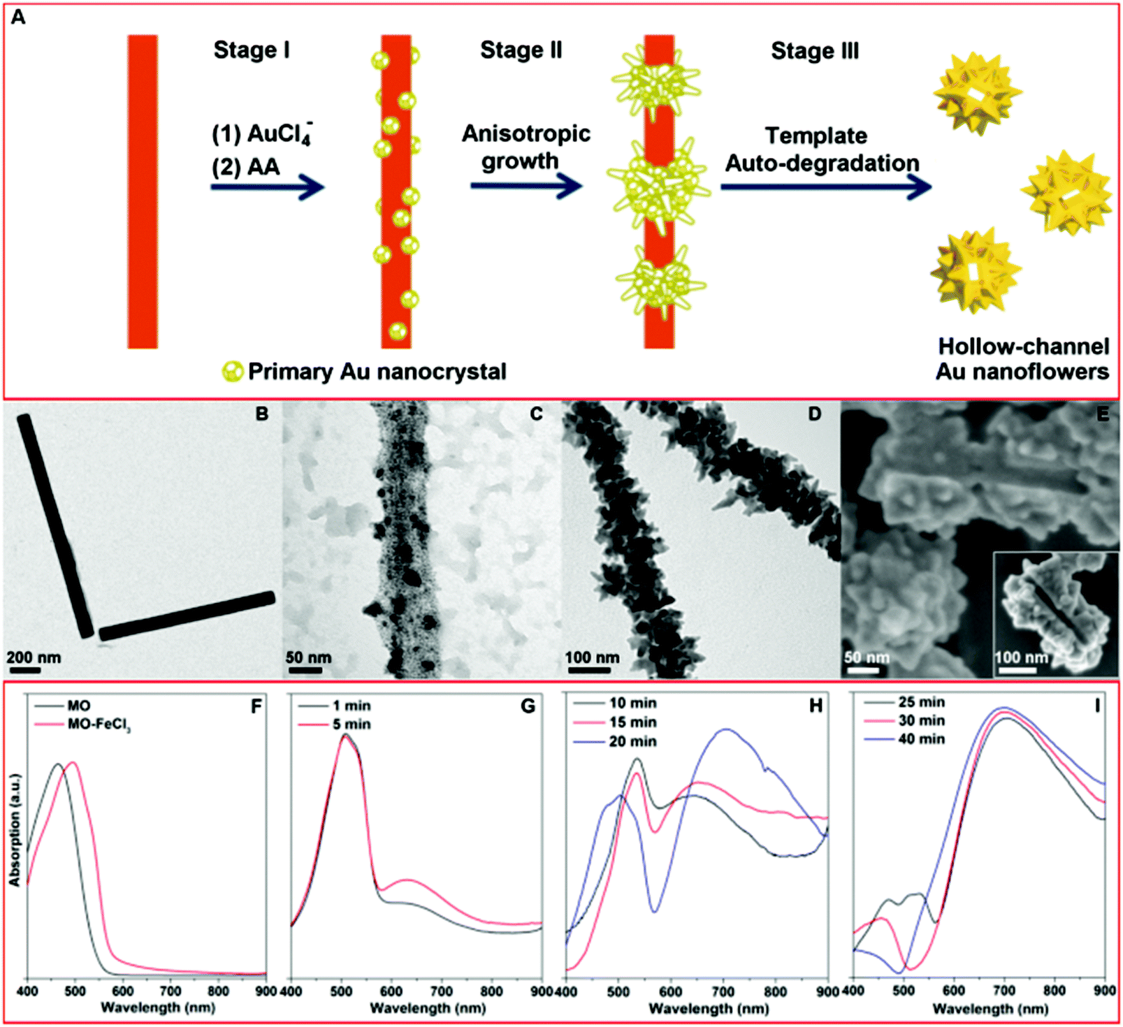 | ||
| Fig. 1 (A) Schematic illustration of the proposed mechanism for the formation of hollow gold nanoflowers: Stage (I) Au nucleates on the template surface; Stage (II) Au primary crystal undergoes anisotropic growth to form branches; Stage (III) the as-formed Au nanoflowers catalyze the degradation of the template in the presence of AA, leaving the open hollow channel and releasing the individual HAuNFs. (B) TEM images of MO–FeCl3 nanofibers. (C)–(E) EM images of the products harvested at different stages. (F) UV-vis absorption spectra of MO aqueous solution and MO–FeCl3 nanofiber dispersion. (G)–(I) UV-vis absorption spectra of aliquots removed from reaction mixtures at various time points. | ||
Different stages of the growth of the HAuNFs (synthesized with 150 mM AA) were studied by electron microscopy (EM). The MO–FeCl3 nanofiber template has been previously employed for the preparation of conducting polymer nanotubes (e.g. polypyrrole).28,29 The nanofiber dispersion (Fig. 1B) was prepared by simply dissolving FeCl3·6H2O in 5 mM methyl orange solution (for details see ESI†). The nanofibers have a rod shape with a width of (74 ± 22) nm (ESI: Fig. S1†).
After the nanofiber templates were added to the HAuCl4 solution, the strong interactions (the coordination between Au(III) and azobenzene in MO molecules,30 as well as the electrostatic interaction between AuCl4− ions and Fe3+) lead the AuCl4− to be absorbed onto the MO–FeCl3 nanofiber (see ESI†). Following the introduction of the reducing agent AA, Au nucleates on the surface of the template to generate the primary Au nanocrystal (Fig. 1C).31 The template hinders isotropic growth of the nanocrystal, thus inducing anisotropic growth of the primary nanocrystals, from which the branches protrude and extend in length, forming the observed flower-shape (Fig. 1D).16 The as-formed AuNFs in turn act as a catalyst towards the degradation of MO in the presence of FeCl3, excess reducing agent AA and O2 in the solution, resulting in the disassembly of the MO–FeCl3 nanofiber template, leaving an open hollow channel in the center of Au NF (The mechanism of template degradation is discussed in detail in ESI.†). The scanning electron microscopy (SEM) images (Fig. 1E and inset showing the connected channel from different orientations) of two partially formed AuNFs, which share one connected hollow channel, demonstrate the growth of the Au crystal around the elongated threading template. The SEM image of the products before purification by centrifugation (ESI: Fig. S2†) shows no trace of nanofiber, which corroborates the auto-destruction of the template. These experimental observations agree well with the schematic illustration shown in Fig. 1A.
The formation of the HAuNFs and the auto-degradation of the template were also indicated by a change in the optical properties. As can be seen from Fig. 1F, the solution of free MO molecules and the MO–FeCl3 dispersion displayed a peak at 465 nm and 505 nm respectively. Shortly after the addition of AA to the mixture of MO–FeCl3 and HAuCl4, the solution turned from an orange color to a ruby color, and a new absorption peak was observed around 530 nm (Fig. 1G), which overlapped with the peak of MO–FeCl3 template. These observations indicate the generation of the primary Au nanocrystals, corresponding to Stage I in the HAuNF formation. As the growth continued, the solution color gradually changed from ruby to purple, and a plasmon band centered at a longer wavelength (∼650 nm) appeared (Fig. 1H), intensified and red-shifted, suggesting the anisotropic growth of the Au nanocrystals to form the branches and correlating well with Stage II. Afterwards, the absorption spectrum displayed a shoulder around 470 nm, which can be ascribed to free MO molecules, due to the disassembly of the MO–FeCl3 template. With the reaction proceeding, the solution color turned from purple to blue and the absorption around 470 nm weakened until it finally disappeared, suggesting the auto-degradation of the template corresponding to Stage III. Noticeably, the long wavelength peak (600–700 nm) assigned to the HAuNFs showed no further red-shift after the peak of MO appeared, revealing that the template destruction occurred after the completed formation of the nanoflower structure. The absorption peak of MO/MO–FeCl3 was absent in the spectrum of the supernatant after centrifugation of the reaction solution (ESI: Fig. S3A†), providing more evidence for the template degradation. To verify that the as-formed HAuNFs catalyzed the degradation of MO–FeCl3 template in the presence of the excess AA, we added purified HAuNFs to the mixture of MO–FeCl3 template and AA solution, the absorption assigned to MO/MO–FeCl3 decreased and then disappeared within 12 min (ESI: Fig. S3B†). In contrast, the absorption of MO–FeCl3 template dispersions was almost unaltered after 3 h, in the absence of either AA or HAuNFs.
Structural and optical properties of HAuNFs
Fig. 2A shows a typical SEM image of as-prepared quasi-spherical nanocrystals with an average overall dimension of (193 ± 47) nm. The XRD pattern (ESI: Fig. S4†) displays five peaks assigned to diffraction from the (111), (200), (220), (311), and (222) planes of face-centered-cubic (fcc) gold, demonstrating the pure and well crystallized nature of the Au nanocrystals produced. The selected area electron diffraction pattern of an individual HAuNF (Fig. S5†) shows a combination of diffraction spots and rings, indicative of the limited polycrystallinity. The SEM image of higher magnification (Fig. 2B) shows more detailed morphology features that these quasi-spherical nanocrystals are flower-shaped, consisting of many randomly arranged, irregular protrusions. In addition, the structural features (highlighted by the arrows in Fig. 2B) indicate the inner cavity. Fig. 2C shows that each individual Au nanoflower has a hollow channel in the center. The hollow structure is further revealed by the SEM image of an incomplete nanoflower (Fig. 2D), which depicts smooth inner wall with the shape and dimensions matching that of the nanofiber template, in agreement with our proposed mechanism for the formation of HAuNFs. Following this synthetic route, HAgNFs (shown in ESI: Fig. S6†) were also obtained applying a slightly modified template (MO–Fe(NO3)3) nanofibers (for details see ESI†).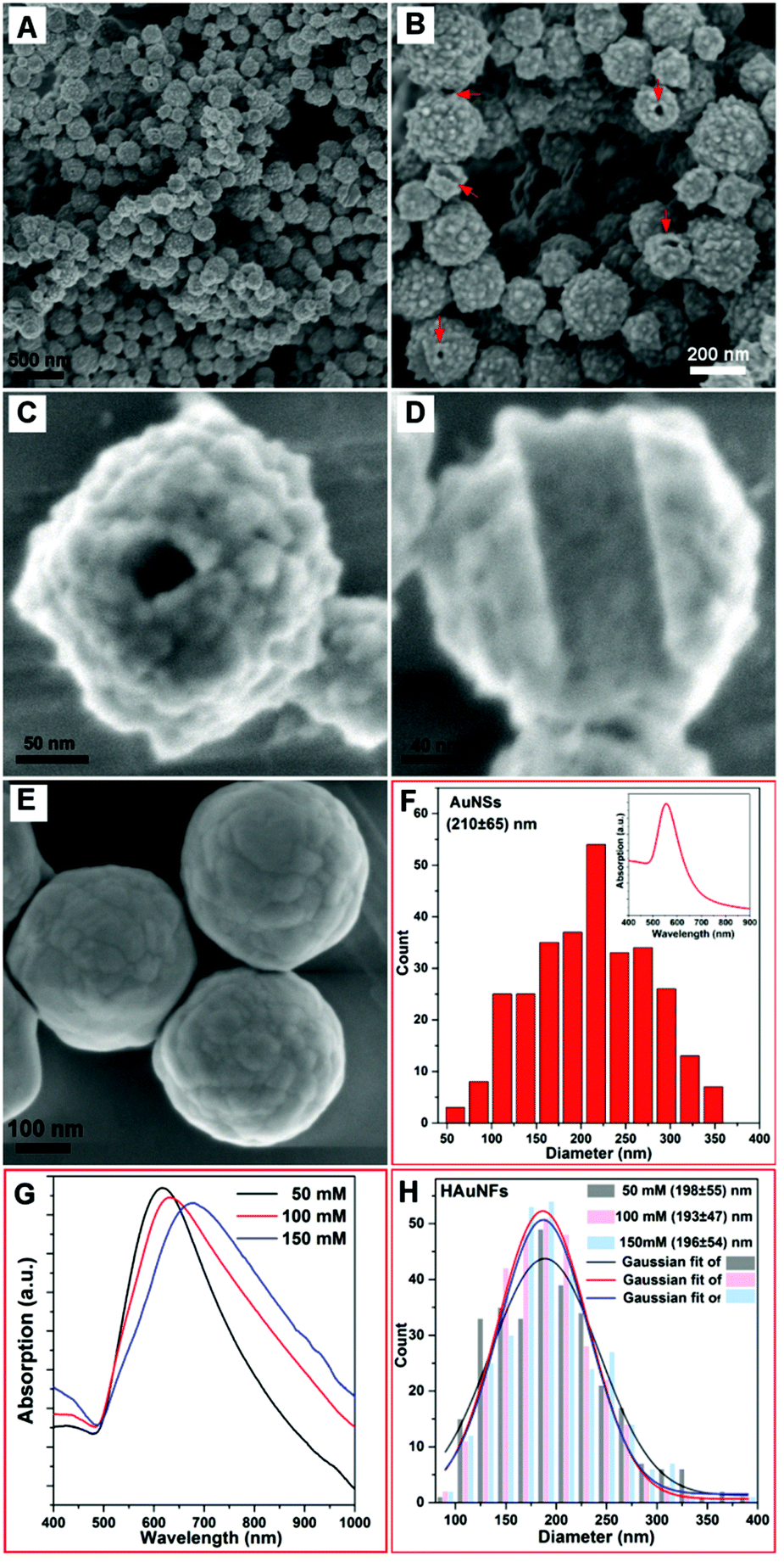 | ||
| Fig. 2 (A) SEM image of the HAuNFs (synthesized with 100 mM AA) at low magnification; (B) SEM image of the HAuNFs at higher magnification with the arrows pointing out the structural defects on the nanoparticle surface indicating the hollow structure; SEM image of an individual nanoflower showing the hollow channel (C) and an incomplete nanoflower (D) displaying the inner wall; (E) SEM image of Au nanoparticles synthesized by adding AA solution to HAuCl4 solution in the absence of template; (F) size distribution of AuNSs (by counting 300 nanoparticles). Inset: UV-vis spectrum of AuNSs; (G) UV-vis absorption spectra of HAuNFs synthesized with different concentrations of AA; (H) Size distributions of HAuNFs synthesized with different concentrations of AA, by counting 300 nanoparticles for each sample. The size represents the overall dimension (longest span) of HAuNF. | ||
In order to investigate the dual roles of the template in the formation of both the hollow channel and the multiple branches on the outer surface, a control experiment for synthesizing Au nanoparticles was performed by adding the AA solution to the HAuCl4 solution in the absence of template. The obtained Au nanoparticles showed similar size distribution of (210 ± 65) nm (Fig. 2F) to that of HAuNFs (Fig. 2H), but they were spherical in shape (ESI: Fig. S7†), exhibited smoother surfaces (Fig. 2E), and had an absorption peak at 550 nm (Inset of Fig. 2F). These results indicate that the templates are critical for the formation of a flower-like morphology, due to the following two effects: (1) physically restricting the nanocrystal growth in a particular direction and hence leading to the anisotropic growth; (2) increasing the local concentration of Au precursor by adsorbing AuCl4− ions, thus enhancing the supersaturation, which is responsible for the formation of the branches.31,32
The surface topography of the HAuNFs is dependent on the concentration of the reducing agent ascorbic acid (AA). Fig. S8A(ESI†) shows that the HAuNFs synthesized with 50 mM AA exhibit a “meatball” shape, of which the branches have the lengths of 5–10 nm and the tip angles >90°. When 100 mM AA was used, the tips of obtained HAuNFs (shown in Fig. 2B) become longer (10–15 nm) and sharper (70°–90°). The use of higher concentration of AA (150 mM) changes the product morphology to sea urchin-like, spike-coated structures, with the spike lengths of 20–30 nm and the tips <50° (ESI: Fig. S8B†), suggesting the length and sharpness of the spikes on the nanoflower surface increase with higher reducing agent concentration, likely caused by the secondary nucleation induced by the larger amount of reducing agent.32,33 The longer spikes and increased roughness of branched gold nanoparticles have been demonstrated to result in the red-shift of SPR.34–36 Similarly, in our work, the absorption peak of the HAuNFs was tuned from 610 nm in the visible region to 690 nm in the near infrared (NIR) region, by increasing the AA concentration from 50 mM to 150 mM (Fig. 2G), while the size distribution did not show discernible variation (Fig. 2H). The NIR absorption suggests that these HAuNFs have potential uses for NIR-based photothermal therapy and enhanced photoacoustic imaging.37
High resolution transmission electron microscopy (HR-TEM) measurements of the HAuNFs (synthesized with 150 mM AA) showed that the spikes had edges and corners (Fig. 3A, ESI: S9A and S10A†), and they exhibit zig-zag features on the borders, demonstrating the presence of low-coordinate atomic steps. Fig. 3B, S9B and S10B† show the atomic steps on the branch surface with a series of (100) and (111) sub-facets. These small facets are combined to form the high-index facets, for examples, (211) and (311) planes composed of (111) terraces and (100) steps, and (411) planes composed of (100) terraces and (111) steps, matching the corresponding atomic models (Fig. 3C, S9C and S10C†) well.38–40 The projection angle (ESI: Fig. S11†) between the surface and the {100} facets confirmed the presence of {211}, {311} and {411} facets.41 In addition, it can be seen from Fig. 3D–F that, a high density of dislocations, steps and kinks are exposed on the HAuNF spikes, which have been reported to be the basis of high catalytic activity in gold catalysts.42,43
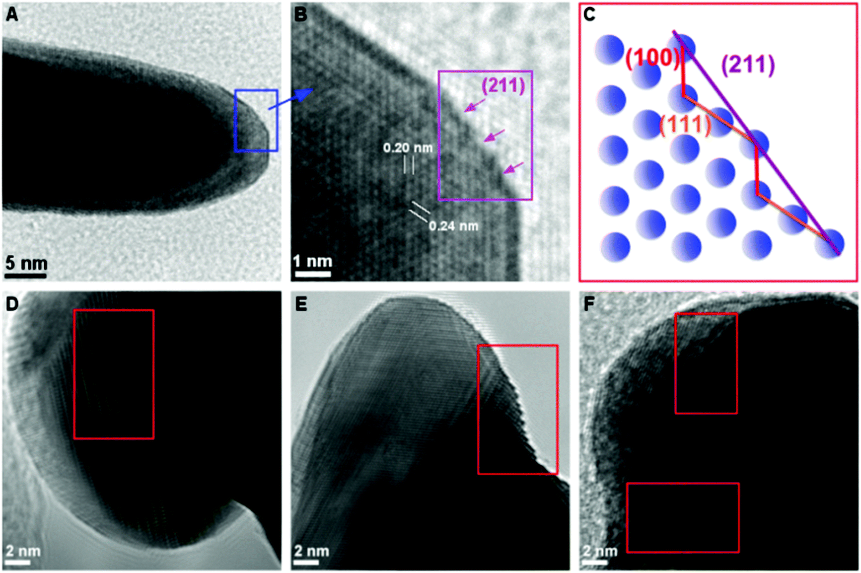 | ||
| Fig. 3 (A) TEM image of one spike of an HAuNF; (B) HR-TEM image from the region indicated within the box in (A) showing the {211} facets made of (111) and (100) sub-facets. (C) The corresponding atomic models of {211} planes projected from the [110] zone axis. (D–F) HR-TEM images of individual spikes displaying dislocation, step and kink features. | ||
The above results show that our HAuNFs integrate several beneficial and attractive morphological/structural properties, on the nano- and atomic-scale, for their use as nanocatalysts, including large surface area, high degree of roughness, a large number of active sites (edges and corners),13,44 high-index facets,45,46 a high density of dislocations, steps and kinks on the branch tips,43 “clean surface” which is free from surfactants conventionally involved in fabricating other types of multiple-branched Au nanostructures and hence more accessible for the reactants.47 Compared with the solid counterpart, the inner surface of HAuNFs increases the total surface area by ∼18.3% (The details of estimating the surface area are shown in ESI.†), the open cavity facilitates the diffusion of reactants to the inner surface, thus effectively activating its catalytic activity,12–14 and the confinement (cage) effect enables the interior cavity to act as a nanoreactor building up the concentrations of the species involved in the reaction.44 Owing to the synergy of these characteristics, our HAuNFs are expected to possess excellent catalytic effect, which was indeed displayed in the aforementioned process in the template degradation stage.
Catalytic performances of HAuNFs
We tested the catalytic performances of the HAuNFs (synthesized with 150 mM AA), using the degradation of methyl orange in the presence of NaBH4 and the reduction of 4-nitrophenol (4-NP) to 4-aminophenol by NaBH4 as two model reactions. As a control, the “smooth” AuNSs (Fig. 2E) were tested under the same conditions. These well-established reactions can be catalyzed by a variety of noble metal nanocrystals and the reaction kinetics can be monitored by spectroscopic measurements. In both reactions, the concentration of NaBH4 is comparatively large with respect to that of MO/4-NP, and can be considered as a constant during the reaction.48,49 Therefore, we assume that pseudo-first-order kinetics with respect to MO/4-NP can be applied. According to equation of first-order kinetics (eqn (1)), the apparent rate constant (kapp) can be determined by calculating the slope of a linear plot of ln(C0/Ct) versus reaction time (t), where C0 and Ct are the concentrations of MO/4-NP at time 0 and t, respectively, and C0/Ct equals to A0/At, where A0 and At are the peak absorbance of MO/4-NP at time 0 and t, respectively.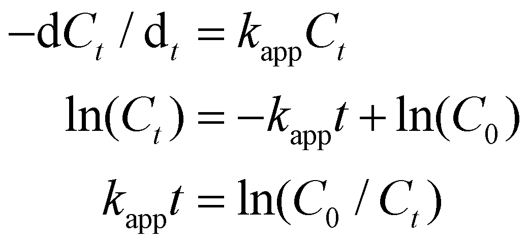 | (1) |
Fig. 4A shows the catalytic degradation of MO with time at 20 °C, and it can be observed that the absorption peak at 465 nm from MO decreases gradually as the reaction proceeds in the presence of HAuNFs (ESI: Scheme S2† depicts the mechanism of catalytic degradation of MO by NaBH4, and Fig. S12† shows the time-dependent UV-vis spectra of MO, in the presence of NaBH4 and AuNSs), and complete degradation occurs within 100 s. The plot of ln[C0/Ct] versus time for these spectra is linear, demonstrating that the reaction follows first-order kinetics. At the concentration of 8 mg l−1, the HAuNFs and AuNSs have respective kapp of 3.4 × 10⁻² s−1 and 1.7 × 10⁻³ s−1. We further measured the kapp in the reaction systems with different concentration of nanocatalysts (HAuNFs or AuNSs), finding that the kapp is proportional to the nanocatalyst concentration, (M, mg l−1). Therefore, we derived the slope of the line (k1) from eqn (2), which reflects the intrinsic catalytic activity.49
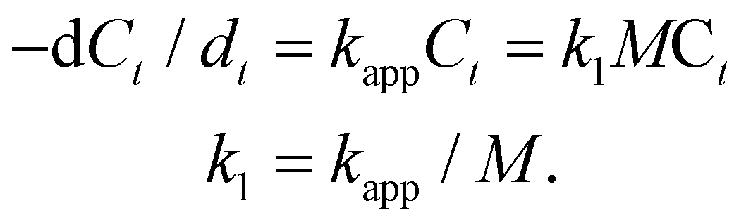 | (2) |
 | ||
| Fig. 4 Catalytic properties of HAuNFs methyl orange degradation: (A) extinction spectra recorded at different reaction time points using HAuNFs (concentration: 8 mg I−1) as catalyst, indicating the disappearance of 465 nm peak owing to the degradation of MO; (B) plots of ln(Ct/C0) versus reaction time for the MO degradation (concentration of HAuNFs/AuNSs: 8 mg l−1); (C) plots of the apparent rate constants (kapp) as a function of the mass concentration (M); (D) conversion within 100 s (Table S2† shows the data for calculating conversions) and kapp against the number of successive cycles. (Concentration of HAuNFs: 8 mg I−1). 4-Nitrophenol reduction: (E) the extinction spectra recorded at different reaction time points using HAuNFs (concentration: 8 mg I−1) as catalyst, showing the decrease in intensity for the peak at 400 nm associated with 4-nitrophenolate as the reduction reaction proceeded; (F) plot of ln(Ct/C0) versus reaction time for the 4-NP reduction (concentration of HAuNFs/AuNSs: 8 mg I−1); (G) plots of the apparent rate constants (kapp) as a function of the mass concentration; (H) conversion within 120 s (Table S3† shows the data for calculating conversions) and kapp against the number of successive cycles (concentration of HAuNFs: 8 mg I−1). The concentration of gold nanoparticles (HAuNFs and AuNSs) in solution was determined using an atomic absorption spectrometer (AAS). | ||
The slope (k1) related to HAuNFs and AuNSs were determined to be 3.99 × 10⁻³ and 2.18 × 10⁻⁴ l s−1 mg−1, which shows that the HAuNFs are ∼18 times more catalytically active than the AuNSs for this reaction.
In addition to activity, stability and reusability are also essential factors and desired properties for the practical applications of catalysts.50,51Fig. 4D shows the plots of kapp and conversion versus the number of successive MO degradation that repeatedly employed the HAuNFs (concentration: 8 mg I−1) as catalyst. Notably, the HAuNF catalyst retained its high activity and achieved high conversions even after 10 cycles.
In the case of the reduction of 4-nitrophenol (4-NP) by NaBH4, we investigated the kinetic process by monitoring the intensity of the absorption peak at 400 nm (assigned to 4-nitrophenolate ions in the mixture of 4-NP and NaBH4). After the addition of HAuNFs, a new peak at 315 nm of the product 4-aminophenol (4-aminophenolate) appeared, and the absorption peak at 400 nm gradually dropped and then disappeared after 120 s. The gas bubbles of H2 evolved by the decomposition of NaBH4 may impede absorbance measurements during the reaction, resulting in the absence of isosbestic points in Fig. 4E (and Fig. S13†).52–54 Because the peak at 400 nm dominated for most of the time, it is reasonable to derive the concentration of 4-NP ions from absorbance at 400 nm and thus to investigate the reaction kinetics.49 The HAuNFs also showed excellent activity (k1 = 3.12 × 10⁻³ l s−1 mg−1 for HAuNFs, while k1 = 4.62 × 10⁻⁴ l s−1 mg−1 for AuNSs), stability and reusability (Fig. 4H showed that no significant loss was observed in the conversion or Kapp after 10 successive cycles). It is noteworthy that, compared with the recently reported solid Au nanostars,55 our HAuNFs enjoy ∼1.7 times of catalytic activity in this model reaction (Table 1).
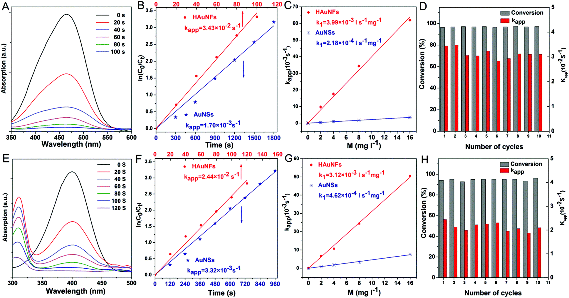
We also examined the electrocatalytic performances of our HAuNFs by adopting electro-oxidation of ethanol as a model reaction. Fig. 5A shows cyclic voltammetry (CV) curves of the ethanol oxidation activities of HAuNFs and AuNSs in a 0.1 M KOH with 0.5 M ethanol solution. The mass normalized peak current density (376.3 mA mg−1) of ethanol oxidation on the HAuNFs in the forward direction scan was ∼30 times of that of AuNSs (11.7 mA mg−1) and ∼3.4 times of that of commercially available Pt black (0.11 A mg−1)41 when measured under the same conditions, demonstrating the superior electrocatalytic activity of our HAuNFs towards ethanol oxidation. It is further noted that the catalytic activity of the HAuNFs was also higher than that of recent state-of-the-art Au-based nanocatalysts, such as Au NPs supported on activated carbon,56 and Au dendritic nanostructures with hyperbranched architectures.57 Furthermore, our HAuNFs with spatially separated spikes drastically suppress the activity loss caused by the undesirable agglomeration of Au active sites, which therefore contribute to the high electrocatalytic stability.58 As shown in Fig. 5B, after 500 cycles, 86.7% of the initial catalytic activity was still maintained.
 | ||
| Fig. 5 Electrocatalytic properties of HAuNFs: (A) cyclic voltammetry curves measured for the HAuNFs and Au nanospheres (AuNSs) in an Ar gas-purged 0.1 M KOH + 0.5 M ethanol solution (B) electrocatalytic stability test of HAuNFs showing the variation of peak current densities of ethanol oxidation during the potential cycling. | ||
Single-particle SERS (spSERS) of HAuNFs
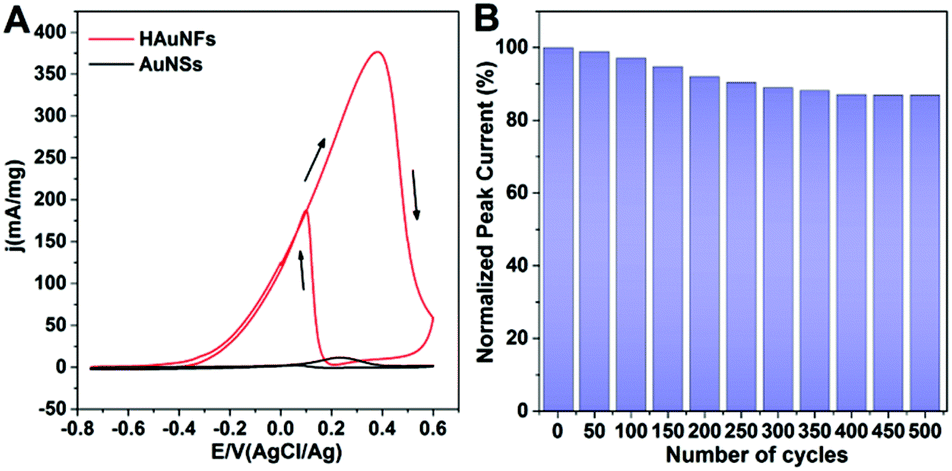
These HAuNFs are also expected to display high local field enhancement, which can be used to increase the signal in Surface Enhanced Raman Spectroscopy (SERS). We used biphenyl-4-thiol (BPT) as a non-resonant Raman reporter molecule to evaluate the Raman enhancements on individual HAuNFs (synthesized with 150 mM AA).The dark-field microscopy image of the HAuNFs on the Si substrate (inset of Fig. 6A) shows that, the individual nanoparticles were well separated from each other, with interparticle distances much larger than the dimension of each particle. As a result, interparticle plasmonic coupling was negligible and should have no contribution to the Raman enhancement. The large interparticle distances allowed us to focus the laser beam on one particle each time, using a confocal Raman microscope to collect single-particle SERS (spSERS) signals.
 | ||
| Fig. 6 (A) SERS spectra of BPT on individual HAuNFs (red line) and AuNSs (black line). Laser wavelength 632.8 nm, 180 μW power, 1 s and 10 s integration time for HAuNF and AuNSs, respectively. The inset shows a typical dark-field optical image of isolated HAuNFs deposited on a silicon substrate. (B) SERS EFs on individual HAuNFs/AuNSs. (C) SEM image of HAuNFs, showing the structural features contributing to the SERS signals. | ||
SERS spectra were collected from 50 individual particles for each sample (HAuNFs or AuNSs), and the average SERS spectra of a monolayer of BPT adsorbed on individual HAuNFs or AuNSs are shown in Fig. 6A. The Raman features of BPT molecules were detectable at single nanoparticle level for both HAuNF and AuNS (The broad Raman mode around 940 cm−1 originates from the used silicon substrate). The spectral features are in good agreement with earlier experimental and theoretical work.59 Strikingly, the SERS intensity on individual HAuNFs was ∼40 times higher compared with that on AuNSs.
We further estimated the enhancement factors (EFs) by comparing SERS signals to normal Raman intensities obtained from neat BPT powders (ESI: Fig. S14†). Two intense Raman bands at 1100 cm−1 (C–H stretching mode) and 1589 cm−1 (phenol ring C–C stretching mode) were chosen for EF estimation (The detailed method for estimating the EFs is described in ESI.†). It can be seen from Fig. 6B that, the phenol ring C–C stretching showed larger enhancements than the C–H stretching mode, most likely due to the stronger coupling between the transition dipole moment and local electric field.34 The EFs were estimated to be on (or close to) the order of 105 for HAuNFs, while on the order of 103 for AuNSs.
Among the structural features of HAuNFs, the open cavity makes the inner walls accessible, and the facing inner walls form nanogaps of several tens of nanometers or even sub-10 nm, greatly enhancing the plasmon electromagnetic field.60,61 Moreover, the increased surface area and roughness, tips, edges, intra-particle gaps and nanoscale porosity between the spikes of the HAuNFs (shown in Fig. 6C) all contribute to significant electromagnetic field enhancements, thus affording strong spSERS signals.62,63
Conclusion
In summary, we have proposed a facile and cost-effective one-step approach to fabricating novel HAuNFs with an open hollow channel in the center and multiple spikes on the outer surface. The simply prepared MO–FeCl3 nanofiber templates play an essential role in both the formation of the hollow channel and the flower-shaped morphology, and undergo auto-degradation catalyzed by the as-formed Au nanoflowers. This approach has also shown applicability to fabricating HAgNFs. Crucially, unlike the conventional template synthesis in which the product tends to inherit the shape or symmetry of the template,19 the dual roles of the nanofiber template lead our hollow-channel nanoflowers to display a geometry and dimensionality distinct from the template, offering innovative ideas for the design of nanostructures via template-assisted synthesis.The optical absorption of these HAuNFs can be modulated to NIR region by tailoring the topology/roughness, without enlarging the dominant dimension of the nanoparticles, providing them with the benefits of both smaller size and NIR absorption desirable for future in vivo applications. Moreover, our HAuNFs enjoy a large surface area, rich edges and corners, an open hollow cavity, high-index facets and a clean surface, which synergistically lead to the excellent (electro) catalytic performances and SERS activity.
It is envisaged that these HAuNFs can be utilized as effective catalysts and SERS probes, and hold potential uses as drug carriers and photothermal conversion agents. We also envisage that our novel synthesis protocol is generic and provides an insight into the room-temperature aqueous phase synthesis of a variety of hollow metal nanomaterials for diverse future applications.
Experimental
Materials
Gold(III) chloride trihydrate (520918), 4-nitrophenol (Fluka-73560), Nafion® perfluorinated resin solution (Aldrich-510211), iron(III) nitrate nonahydrate (Fe(NO3)3·9H2O, 254223) and ethanol (32221) were purchased from Sigma-Aldrich. L-(+)-Ascorbic acid (A15613), iron(III) chloride hexahydrate (FeCl3·6H2O, A16231), methyl orange (ACS, 17874) and silver nitrate (11414) were purchased from Alfa Aesar. Sodium borohydride (NaBH4, 10599010), hydrochloric acid (37%, UN1789), potassium hydroxide (KOH, P/5640/53) and nitric acid (70%, UN2031) were purchased from Fisher Scientific. All chemicals were used without further purification.Reaction preparation
Vials were cleaned with aqua regia (nitric acid and hydrochloric acid in a volume ratio of 1![[thin space (1/6-em)]](https://www.rsc.org/images/entities/char_2009.gif) :3) thoroughly rinsed with DI water, and dried in an 80 °C oven before use. Once dry, the flasks were allowed to cool to room temperature before any reactants were added.
:3) thoroughly rinsed with DI water, and dried in an 80 °C oven before use. Once dry, the flasks were allowed to cool to room temperature before any reactants were added.
Synthesis of hollow-channel Au Nanoflowers (HAuNFs)
In a typical procedure, 13.5 mg of FeCl3·6H2O was dissolved in 1 ml of 5 mM methyl orange aqueous solution to prepare the template dispersions. 120 μl of the template dispersion and 2 ml of ascorbic acid aqueous solution (50 mM, 100 mM or 150 mM) were added sequentially into 2 ml HAuCl4 aqueous solution (5 mM) without stirring. After an undisturbed growth for 45 min at room temperature, the reaction products were isolated by centrifugation at 1000 rpm (188g) for 10 min followed by removal of the supernatant. The pellet was washed with Milli-Q twice. The final product of HAuNFs was collected in Milli-Q.Synthesis of Au Nanospheres (AuNSs)
120 μl Milli-Q and 2 ml of ascorbic acid aqueous solution (150 mM) were added sequentially into 2 ml HAuCl4 aqueous solution (5 mM) without stirring. After an undisturbed growth for 45 min at room temperature, the reaction products were isolated by centrifugation at 1000 rpm (188g) for 10 min followed by removal of the supernatant. The pellet was washed with Milli-Q twice. The final product of AuNSs was collected in Milli-Q.Synthesis of hollow-channel Ag Nanoflowers (HAgNFs)
In a typical procedure, 20.2 mg of Fe(NO3)3·9H2O was dissolved in 1 ml of 5 mM methyl orange aqueous solution to prepare the template dispersions. 120 μl of the template dispersion and 2 ml of ascorbic acid aqueous solution (100 mM) were added sequentially into 2 ml AgNO3 aqueous solution (5 mM) without stirring. After an undisturbed growth for 90 min at room temperature, the reaction products were isolated by centrifugation at 1000 rpm (188g) for 10 min followed by removal of the supernatant. The pellet was washed with Milli-Q twice. The final product of HAuNFs was collected in Milli-Q.Characterizations
The UV-vis absorption spectra were recorded with a Perkin-Elmer Model Lambda35 spectrophotometer. SEM micrographs were obtained using a Hitachi SU8230. Each SEM sample was prepared by placing 5 μl nanoparticle dispersion (in Milli-Q) onto an aluminium substrate and drying at room temperature naturally. A transmission electron microscope (TEM; Tecnai™ G2 Spirit TWIN/BioTWIN) with an acceleration voltage of 120 kV was used to take lower resolution TEM images. A field emission gun TEM microscope (Philips CM200 FEGTEM; 200 kV) equipped with a Gatan GIF200 imaging filter running DigitalMicrograph software was used to take higher magnification TEM images and energy dispersive X-ray spectroscopy (EDX). For preparing for the TEM samples, 5 μl nanoparticle dispersion (in Milli-Q) was dropped onto a carbon-coated copper grid and dried at room temperature naturally. The XRD pattern was obtained by using a Panalytical Model X'Pert Pro MPD X-ray diffractometer with Cu Kα source and an X'cellerator detector. A continuous scan over a 2θ range from 30° to 90° was performed with an acquisition time of 1 h per sample at a step size of 0.05°. Samples were prepared by depositing and drying slurries directly on low-background Si sample holders. The concentration of gold nanoparticles (HAuNFs and AuNSs) in solution was determined using an atomic absorption spectrometer (AAS, Varian 240fs).Catalytic degradation of methyl orange (MO) and reduction of 4-nitrophenol (4-NP)
(2) Since the catalytic activity of HAuNFs was independent of their concentration, we tracked the variation in their catalytic activity by repeated addition of new MO.64 After each cycle of reaction proceeded for 100 s, another 10 μl of MO aqueous solution (5 mM) was added to the reaction system.
(3) Following the protocol in (1), the catalytic activities of HAuNFs/AuNSs at different concentrations were measured by adding 10 μl dispersions of HAuNFs/AuNSs (200 μg ml−1, 400 μg ml−1 or 1600 μg ml−1, respectively corresponding to 2 mg l−1, 4 mg l−1 and 16 mg l−1 in the reaction system).
(2) Since the catalytic activity of HAuNFs was independent of their concentration, we tracked the variation in their catalytic activity by repeated addition of new 4-NP.64 After each cycle of reaction proceeded for 120 s, another 10 μl of 4-NP aqueous solution (20 mM) was added to the reaction system. This step was repeated ten times to investigate the stability of catalyst particles.
(3) Following the protocol in (1), the catalytic activities of HAuNFs/AuNSs at different concentrations were measured by adding 10 μl dispersions of HAuNFs/AuNSs (200 μg ml−1, 400 μg ml−1 or 1600 μg ml−1, respectively corresponding to 2 mg l−1, 4 mg l−1 and 16 mg l−1 in the reaction system).
Electrocatalytic performances of HAuNFs (or AuNSs) towards ethanol oxidation (cyclic voltammetry measurements)
Cyclic voltammetry (CV) measurements were conducted in a conventional three-electrode glass cell using an Autolab electrochemical analyzer (Ecochemie, Utrecht, Netherlands) equipped with a PGSTAT128N potentiostat. The HAuNFs and AuNSs were drop-casted on freshly polished pyrolytic graphite ‘edge’ electrodes (PGE, diameter = 3 mm), which served as working electrodes. The glassy carbon electrodes were polished with an aqueous slurry of 1 μm alumina particles and briefly immersed in water in a bath sonicator to remove the alumina. A Pt wire and a Ag/AgCl (saturated KCl, Radiometer) were used as the counter and reference electrodes, respectively. Prior to conducting the CV measurements, 1 μl of an aqueous Au nanoparticle (HAuNFs or AuNSs) solution was placed onto the PGE surface and dried in air for about 10 minutes. After the solution was dried, 10 μl of a Nafion solution (ca. 0.05%, prepared by mixing 10 μl Nafion® perfuorinated resin solution of 5% w/v, 440 μl Milli-Q and 550 μl ethanol) was added, followed by being dried in a desiccator for 30 min. The dried PGE were rinsed sequentially with ethanol and water, and then electrochemically cleaned by 20 potential cycles between −0.75 and 0.60 V (vs. Ag/AgCl) in 0.1 M KOH and 0.5 M ethanol mixed solution at a scan rate of 50 mV s−1. All CVs were obtained at room temperature, and the electrolyte solutions were thoroughly purged with argon.Single-particle SERS of HAuNFs (or AuNSs)
Both HAuNFs and AuNSs were deposited on a silicon substrate by drop-casting. The drop-casting time was adjusted to obtain a uniform but sparse sample allowing single particle analysis. Subsequently the samples were rinsed with deionized H2O, blown dry, and submerged in a 10 mM BPT solution in EtOH for 1 h. A home-built dark field Raman microscope was used to collect the SERS spectra of one particle at a time. A helium neon laser (632.8 nm) was coupled into an Olympus BX51 microscope. All experiments were performed using a long working distance 100× objective (NA = 0.8) and a laser power of 0.18 mW (on the sample). The signal was collected using an Andor Shamrock i303 spectrograph and an Andor Newton EMCCD.Author contribution
SY, JJB, LJ, KC and SDE conceived the experiments. SY, FB and MW performed experiments, with the assistance from JO in electrochemistry. SY and FB analysed the data. SY, FB, HKC, OC, KC and SDE wrote the paper. All authors contributed to the paper.Acknowledgements
The authors would like to thank the following for financial support: SY (Wellcome ISSF Junior Investigator Development Fellowship) FB (the Winton Programme for the Physics of Sustainability). SY, KC and SDE (MRC-CiC), SDE (NIHR RG. TASS485204), HKC (EPSRC grant EP/N002423/1), LJCJ and JO (European Research Council under the European Union's Seventh Framework Programme (FP/2007-2013)/ERC Grant Agreement n. 280518). JJB (EPSRC EP/G060649/1 and EP/L027151/1, and ERC grant LINASS 320503). SY thanks the following for suggestions and support: Dr Bin Zhao, Dr Huanhuan Gao and Dr Yunxing Li (discussions), Dr Mike Ward, Dr Peiyi Wang and Martin Fuller (TEM), Stuart Micklethwaite and John Harrington (SEM).Notes and references
- F. Bai, Z. Sun, H. Wu, R. E. Haddad, X. Xiao and H. Fan, Nano Lett., 2011, 11, 3759 CrossRef CAS PubMed.
- Y. G. Sun, B. Mayers and Y. N. Xia, Adv. Mater., 2003, 15, 641 CrossRef CAS.
- J. You, G. Zhang and C. Li, ACS Nano, 2010, 4, 1033 CrossRef CAS PubMed.
- A. M. Gobin, M. H. Lee, N. J. Halas, W. D. James, R. A. Drezek and J. L. West, Nano Lett., 2007, 7, 1929 CrossRef CAS PubMed.
- Y. Ma, X. Liang, S. Tong, G. Bao, Q. Ren and Z. Dai, Adv. Funct. Mater., 2013, 23, 815 CrossRef CAS.
- B. L. Sanchez-Gaytan, P. Swanglap, T. J. Lamkin, R. J. Hickey, Z. Fakhraai, S. Link and S.-J. Park, J. Phys. Chem. C, 2012, 116, 10318 CrossRef CAS.
- H.-n. Xie, I. A. Larmour, W. E. Smith, K. Faulds and D. Graham, J. Phys. Chem. C, 2012, 116, 8338 CrossRef CAS.
- H. P. Liang, H. M. Zhang, J. S. Hu, Y. G. Guo, L. J. Wan and C. L. Bai, Angew. Chem., Int. Ed., 2004, 43, 1540 CrossRef CAS PubMed.
- J. Zeng, Q. Zhang, J. Chen and Y. Xia, Nano Lett., 2010, 10, 30 CrossRef CAS PubMed.
- X. Li, L. Zhou, Y. Wei, A. M. El-Toni, F. Zhang and D. Zhao, J. Am. Chem. Soc., 2015, 137, 5903 CrossRef CAS PubMed.
- G. Guan, Z. Zhang, Z. Wang, B. Liu, D. Gao and C. Xie, Adv. Mater., 2007, 19, 2370 CrossRef CAS.
- S. Mandal, M. Sathish, G. Saravanan, K. K. R. Datta, Q. Ji, J. P. Hill, H. Abe, I. Honma and K. Ariga, J. Am. Chem. Soc., 2010, 132, 14415 CrossRef CAS PubMed.
- Q. Shi, P. Zhang, Y. Li, H. Xia, D. Wang and X. Tao, Chem. Sci., 2015, 6, 4350 RSC.
- J. Xu, A. Ma, Z. Xu, X. Liu, D. Chu and H. Xu, J. Phys. Chem. C, 2015, 119, 28055 CrossRef CAS.
- W. J. Cho, A. Jung, S. Han, S.-M. Lee, T. Kang, K.-H. Lee, K. C. Choi and J. K. Kim, NPG Asia Mater., 2015, 7, e167 CrossRef CAS.
- J. Xie, Q. Zhang, J. Y. Lee and D. I. C. Wang, ACS Nano, 2008, 2, 2473 CrossRef CAS PubMed.
- C. Y. Song, N. Zhou, B. Y. Yang, Y. J. Yang and L. H. Wang, Nanoscale, 2015, 7, 17004 RSC.
- J. Lee, B. Hua, S. Park, M. Ha, Y. Lee, Z. Fan and H. Ko, Nanoscale, 2014, 6, 616 RSC.
- B. Lim and Y. Xia, Angew. Chem., Int. Ed., 2011, 50, 76 CrossRef CAS PubMed.
- B. Van de Broek, N. Devoogdt, A. D'Hollander, H.-L. Gijs, K. Jans, L. Lagae, S. Muyldermans, G. Maes and G. Borghs, ACS Nano, 2011, 5, 4319 CrossRef CAS PubMed.
- Y. Liu, J. Goebl and Y. Yin, Chem. Soc. Rev., 2013, 42, 2610 RSC.
- W. Wang, Y. Han, M. Tian, Y. Fan, Y. Tang, M. Gao and Y. Wang, ACS Appl. Mater. Interfaces, 2013, 5, 5709 Search PubMed.
- Y. G. Sun, B. T. Mayers and Y. N. Xia, Nano Lett., 2002, 2, 481 CrossRef CAS.
- Y.-C. Pu, J. R. Hwu, W.-C. Su, D.-B. Shieh, Y. Tzeng and C.-S. Yeh, J. Am. Chem. Soc., 2006, 128, 11606 CrossRef CAS PubMed.
- Z. Li, W. Li, P. H. C. Camargo and Y. Xia, Angew. Chem., Int. Ed., 2008, 47, 9653 CrossRef CAS PubMed.
- C. B. Gao, Q. Zhang, Z. D. Lu and Y. D. Yin, J. Am. Chem. Soc., 2011, 133, 19706 CrossRef CAS PubMed.
- M. R. Jones, K. D. Osberg, R. J. Macfarlane, M. R. Langille and C. A. Mirkin, Chem. Rev., 2011, 111, 3736 CrossRef CAS PubMed.
- X. M. Yang, Z. X. Zhu, T. Y. Dai and Y. Lu, Macromol. Rapid Commun., 2005, 26, 1736 CrossRef CAS.
- M. Joulazadeh and A. H. Navarchian, Synth. Met., 2015, 199, 37 CrossRef CAS.
- M. Concepción, The Chemistry of Gold Modern, Supramolecular Gold Chemistry: Gold-Metal Interactions and Applications, ed. A. Laguna, WILEY-VCH Verlag GmbH & Co. KGaA, Weinheim 1, 2008 Search PubMed.
- H. Wang and N. J. Halas, Adv. Mater., 2008, 20, 820 CrossRef CAS.
- J. Fang, S. Du, S. Lebedkin, Z. Li, R. Kruk, M. Kappes and H. Hahn, Nano Lett., 2010, 10, 5006 CrossRef CAS PubMed.
- D.-J. Guo and S.-K. Cui, J. Phys. Chem. C, 2008, 112, 16348 CrossRef.
- Q. Zhang, N. Large and H. Wang, ACS Appl. Mater. Interfaces, 2014, 6, 17255 Search PubMed.
- S. Pedireddy, A. Li, M. Bosman, I. Y. Phang, S. Li and X. Y. Ling, J. Phys. Chem. C, 2013, 117, 16640 CrossRef CAS.
- J. Rodriguez-Fernandez, A. M. Funston, J. Perez-Juste, R. A. Alvarez-Puebla, L. M. Liz-Marzan and P. Mulvaney, Phys. Chem. Chem. Phys., 2009, 11, 5909 RSC.
- S. J. Ye, G. Marston, J. R. McLaughlan, D. O. Sigle, N. Ingram, S. Freear, J. J. Baumberg, R. J. Bushby, A. F. Markham, K. Critchley, P. L. Coletta and S. D. Evans, Adv. Funct. Mater., 2015, 25, 2117 CrossRef CAS.
- Z. Quan, Y. Wang and J. Fang, Acc. Chem. Res., 2013, 46, 191 CrossRef CAS PubMed.
- N. Tian, J. Xiao, Z.-Y. Zhou, H.-X. Liu, Y.-J. Deng, L. Huang, B.-B. Xu and S.-G. Sun, Faraday Discuss., 2013, 162, 77 RSC.
- X. Huang, Z. Zhao, J. Fan, Y. Tan and N. Zheng, J. Am. Chem. Soc., 2011, 133, 4718 CrossRef CAS PubMed.
- L.-F. Zhang, S.-L. Zhong and A.-W. Xu, Angew. Chem., Int. Ed., 2013, 52, 645 CrossRef CAS PubMed.
- T. Fujita, P. F. Guan, K. McKenna, X. Y. Lang, A. Hirata, L. Zhang, T. Tokunaga, S. Arai, Y. Yamamoto, N. Tanaka, Y. Ishikawa, N. Asao, Y. Yamamoto, J. Erlebacher and M. W. Chen, Nat. Mater., 2012, 11, 775 CrossRef CAS PubMed.
- S. Pedireddy, A. Li, M. Bosman, I. Y. Phang, S. Li and X. Y. Ling, Nat. Commun., 2014, 5, 4947 CrossRef CAS PubMed.
- M. A. Mahmoud, R. Narayanan and M. A. El-Sayed, Acc. Chem. Res., 2013, 46, 1795 CrossRef CAS PubMed.
- A. Mohanty, N. Garg and R. C. Jin, Angew. Chem., Int. Ed., 2010, 49, 4962 CrossRef CAS PubMed.
- N. Tian, Z.-Y. Zhou, N.-F. Yu, L.-Y. Wang and S.-G. Sun, J. Am. Chem. Soc., 2010, 132, 7580 CrossRef CAS PubMed.
- A. Garcia-Leis, A. Torreggiani, J. Vicente Garcia-Ramos and S. Sanchez-Cortes, Nanoscale, 2015, 7, 13629 RSC.
- R. Rajesh, S. S. Kumar and R. Venkatesan, New J. Chem., 2014, 38, 1551 RSC.
- R. He, Y.-C. Wang, X. Wang, Z. Wang, G. Liu, W. Zhou, L. Wen, Q. Li, X. Wang, X. Chen, J. Zeng and J. G. Hou, Nat. Commun., 2014, 5, 4327 CAS.
- M. Shao, F. Ning, J. Zhao, M. Wei, D. G. Evans and X. Duan, Adv. Funct. Mater., 2013, 23, 3513 CrossRef CAS.
- Z. Jin, F. Wang, F. Wang, J. Wang, J. C. Yu and J. Wang, Adv. Funct. Mater., 2013, 23, 2137 CrossRef CAS.
- H. Yamamoto, H. Yano, H. Kouchi, Y. Obora, R. Arakawa and H. Kawasaki, Nanoscale, 2012, 4, 4148 RSC.
- M. Li and G. Chen, Nanoscale, 2013, 5, 11919 RSC.
- Y. Zhang, Z. Cui, L. Li, L. Guo and S. Yang, Phys. Chem. Chem. Phys., 2015, 17, 14656 RSC.
- P. Ndokoye, X. Li, Q. Zhao, T. Li, M. O. Tade and S. Liu, J. Colloid Interface Sci., 2016, 462, 341 CrossRef CAS PubMed.
- S. Yan, L. Gao, S. Zhang, W. Zhang, Y. Li and L. Gao, Electrochim. Acta, 2013, 94, 159 CrossRef CAS.
- J. Huang, X. Han, D. Wang, D. Liu and T. You, ACS Appl. Mater. Interfaces, 2013, 5, 9148 Search PubMed.
- L. Wang and Y. Yamauchi, J. Am. Chem. Soc., 2013, 135, 16762 CrossRef CAS PubMed.
- F. Benz, C. Tserkezis, L. O. Herrmann, B. de Nijs, A. Sanders, D. O. Sigle, L. Pukenas, S. D. Evans, J. Aizpurua and J. J. Baumberg, Nano Lett., 2015, 15, 669 CrossRef CAS PubMed.
- L. Zhang, T. Liu, K. Liu, L. Han, Y. Yin and C. Gao, Nano Lett., 2015, 15, 4448 CrossRef CAS PubMed.
- W. Kubo and S. Fujikawa, Nano Lett., 2011, 11, 8 CrossRef CAS PubMed.
- M. Yang, R. Alvarez-Puebla, H.-S. Kim, P. Aldeanueva-Potel, L. M. Liz-Marzan and N. A. Kotov, Nano Lett., 2010, 10, 4013 CrossRef CAS PubMed.
- Q. Zhang, N. Large, P. Nordlander and H. Wang, J. Phys. Chem. Lett., 2014, 5, 370 CrossRef CAS PubMed.
- T. Yu, J. Zeng, B. Lim and Y. Xia, Adv. Mater., 2010, 22, 5188 CrossRef CAS PubMed.
Footnote |
| † Electronic supplementary information (ESI) available: Fig. S1–S14, Tables S1–S3 and Schemes S1–S4. See DOI: 10.1039/c6nr04045d. The data presented in this article are openly available from the University of Leeds data repository http://dx.doi.org/10.5518/66. |
| This journal is © The Royal Society of Chemistry 2016 |