 Open Access Article
A biologically inspired attachable, self-standing nanofibrous membrane for versatile use in oil–water separation†
Mizuki
Tenjimbayashi
,
Kaichi
Sasaki
,
Takeshi
Matsubayashi
,
Jyunichiro
Abe
,
Kengo
Manabe
,
Sachiko
Nishioka
and
Seimei
Shiratori
*
School of Integrated Design Engineering, Keio University, 3-14-1 Hiyoshi, Yokohama, 223-8522, Japan. E-mail: shiratori@appi.keio.ac.jp
First published on 4th May 2016
Abstract
Uloborus walckenaerius spider webs provided the inspiration for attachable, self-standing nanofibre sheets. The developed product adds selective wettability against oil–water mixtures to both 2D and 3D materials by attaching or covering them, leading to successful separation through a facile, scalable and low-cost process.
Oil pollution in water is a worldwide problem, causing long-term effects on the health of living organisms and the environment.1,2 However, high-purity oil is an important energy resource on which humans depend to maintain their current lifestyle.3 The refuse disposal systems currently available for industrial effluents from factories or for burning rubbish are both expensive and time-consuming.4 It is therefore important to develop methods for the extraction of oil and other chemical pollutants and to remove pure oil from water.5
Recent approaches to oil–water separation are based on the selective wetting of oils, chemicals and water onto 2D or 3D porous materials.6 The techniques for oil–water separation include: (i) modifying nano- and microporous 2D structures with alkyl- or fluoroalkyl-terminated compounds to design (super)hydrophobic and (super)oleophilic porous sheets;7,8 (ii) modifying nano- and microporous structures with compounds containing –OH groups to make superhydrophilic and superoleophobic surfaces under water or hygro-responsive conditions;9–11 (iii) modifying natural 3D porous structures with compounds containing alkyl chains;12,13 (iv) synthesizing 3D-structured materials via freeze-drying methods using a cross-linked hydrophobic polymer to design (super)hydrophobic and oil-absorbable 3D materials;14,15 and (v) designing porous surfaces with an omniphobic lubricant to open pores triggered by variations in pressure to selectively pass liquids through the membrane (inspired by the gating mechanism of plant stoma).16
In these approaches, the materials designed for oil–water separation need to make use of both 2D and 3D structured porous solids with a specific supporting body. This technology has already achieved the highly effective and continuous separation of oil from mixtures and emulsions using strategies of oil–water filtration,17,18 oil absorption12,19,20 and oil collection.21–23 The challenges of oil–water separation are: (i) adding other functions, such as transparency,18 durability,23 self-healing24 and a stimuli-response;10,25 (ii) working under special conditions at different pressures26 or under ambient conditions at different temperatures,13 or in the presence of other chemicals;1 and (iii) making this technology scalable, facile and low cost.6,11 The last requirement, in particular, is essential in practical applications. Hence our aim was to develop a scalable, facile and low-cost material that could be applied to both 2D and 3D structured porous solids for various wetting-controlled oil–water separation techniques.
Our strategy was to design a self-standing sheet for oil–water separation that could be attached to various materials to provide this function to both 2D and 3D materials. The conventional approach to this requires chemical bonding or physical cross-linking between the supporting material and the functional material; however, this type of versatile attachment is difficult to design.
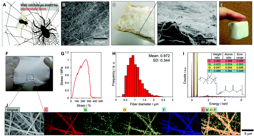
Nature offers a remarkably simple alternative idea. The spider Uloborus walckenaerius weaves an electrically charged thread into fluffed nanofibres from individual spigots using specialized combs on its legs. The webs capture flying insects by electrostatic van der Waals forces (Fig. 1A).27,28 Inspired by this capture mechanism,29 we designed a randomly aligned nanofibre sheet (NF-S) using the easily chargeable fluorine polymer of poly(vinylidene fluoride-co-hexafluoropropylene) (PVDF-HFP) (Fig. 1B). Electrostatic van der Waals forces enabled the NF-S to attach to various materials, such as a Kimtowel and a finger (Fig. 1C–E).30
The NF-S was fabricated by an electrospinning method, resulting in the facile design of various oil–water separating devices (Fig. S1†). The NF-S, with adjustable wettability, strength and elastic properties provided by ethyl-alpha-cyanoacrylate (Et-CA), was successful in oil–water separation with both a 2D structure using a self-standing NF-S and a 3D structure by attaching an NF-S. Indeed, a self-standing property of NF-S is shown in Fig. 1F. It may also be possible to design an advanced oil–water separator by selecting a functional material as the supporting body for the NF-S. The new NF-S could have oil–water separation. The cost of the materials used to fabricate the NF-S reported here (PVDF-HFP, Et-CA and acetone) was about US$ 0.88 m−2 (Table S1†). The NF-S is self-standing and stretchable. The maximum strain of the NF-S was about 250% at a stress >1 MPa (Fig. 1G). The fracture behaviour of the NF-S in a strain–stress test was gradual, meaning that the thinner fibres within the sheet fractured first, then the thicker fibres, resulting in a gradual decrease in the stress at strains >250%. The distribution of the fibre diameters within the NF-S is shown in Fig. 1H; these ranged from 0.3 to 2.5 μm with a mean diameter of 0.972 ± 0.344 μm. Thus a mixture of microfibres and nanofibres provided the strength of the NF-S. The thickness of the NF-S was about 135 μm (Fig. S2† shows a cross-sectional scanning electron microscopy image of the NF-S). The surface chemistry of the fibres was analysed by energy-dispersive X-ray spectrosmetry (EDX) (Fig. 1I and J). The NF-S was composed of PVDF-HFP (hydrogen, carbon and fluorine) and Et-CA (hydrogen, carbon, nitrogen and oxygen). The EDX mapping (Fig. 1I) showed carbon, nitrogen, oxygen and fluorine peaks. The existence of fluorine indicates the presence of PVDF-HFP. The atomic ratio of nitrogen to oxygen was about 1![[thin space (1/6-em)]](https://www.rsc.org/images/entities/char_2009.gif) :
:![[thin space (1/6-em)]](https://www.rsc.org/images/entities/char_2009.gif) 2, which means that the fibres included Et-CA. The EDX analysis confirmed that each element was included within the fibres (Fig. 1J). The strength, strain, fibre diameter and wettability of the NF-S was controlled by changing the weight ratio of PVDF-HFP to Et-CA (Table S2 and Fig. S3–S8†).
2, which means that the fibres included Et-CA. The EDX analysis confirmed that each element was included within the fibres (Fig. 1J). The strength, strain, fibre diameter and wettability of the NF-S was controlled by changing the weight ratio of PVDF-HFP to Et-CA (Table S2 and Fig. S3–S8†).
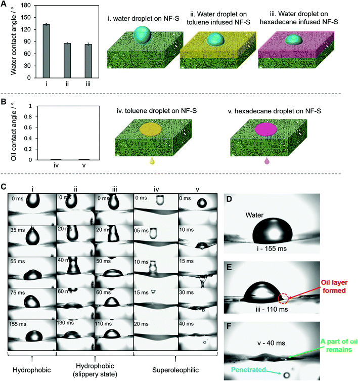
The NF-S is characterized by a selective wettability for oil–water separation. We studied the water blocking and oil penetration mechanisms for the NF-S in detail (Fig. 2). The contact angles of water and oils on the NF-S surface are shown in Fig. 2A and B, respectively. The water blocking ability of the NF-S was tested for the bare NF-S (Fig. 2Ai), toluene-infused NF-S (Fig. 2Aii) and hexadecane-infused NF-S (Fig. 2Aiii). The water droplets did not penetrate the surface under any of these conditions. Fig. 2Biv and v show that the oil droplets (toluene and hexadecane, respectively) penetrated the bare NF-S. Fig. 2C shows time-lapsed images for each of these examples (i)–(v). In example (i) (Fig. 2D), the NF-S showed the highest hydrophobic state towards the water droplet, which did not penetrate the surface. In examples (ii) and (iii), we found that an oily layer formed on the NF-S surface and blocked water invasion (as a result of the immiscibility of oil and water) (Fig. 2E, example (iii)).31Fig. 2F shows an image of an oil droplet that penetrated the NF-S. Some of the oil remained on the surface of the NF-S, but most of the oil penetrated the NF-S, which allowed oil–water separation. The oil layer formed because of the capillary action from the high surface area of the NF-S (1.12 m2 g−1 determined by the Brunauer–Emmett–Teller method). This type of oil layer can block water; the mechanism is similar to that used to design a micro-sponge surface that retains oily liquids (SLIPS), which allows water to slide because of the immiscibility of water with oil.32,33 We found that the limit of wetting or repelling was a surface tension of 36.09–38.56 mN m−1 (Fig. S9†).
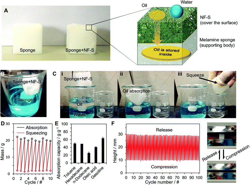
We applied the NF-S to three types of applications: oil absorption, oil–water separation and oil collection. Selective wetting is well known in oil–water separation using each of these methods. Fig. 3 shows the application of oil absorption. A melamine sponge was covered with a NF-S to create a 3D-structured separator (Fig. 3A). Although the sponge was naturally omniphilic, the sponge + NF-S showed hydrophobicity (Fig. 3B) and superoleophilicity. The oil absorbent was used in processes (i)–(iii) in Fig. 3C (Movie S1†). The merit of the combination of sponge + NF-S is that the absorbed oil can be easily extracted for re-use, whereas other oil absorption methods require more complex extraction processes such as heating.12,20 This feature comes from the flexibility of the NF-S. The NF-S maintained its structure after oil extraction (Fig. S10†) to realize repeatable oil absorption and extraction without deterioration (Fig. 3D) with a high absorption capacity for various types of oil (Fig. 3E). We also conducted a compression test to determine the 3D structural retention, which showed the high stability of the sponge structures (Fig. 3F). These functions were derived from the natural properties of the melamine sponge. Thus we added a selective wetting property to the sponge, which already had stable liquid storage properties and high compression durability. This is an example of an addition of function to an already functional material to create an advanced material.
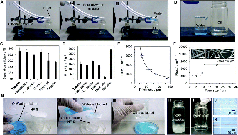
Fig. 4 shows the application of the material in an oil–water filter. The NF-S was attached to the tip of a PVC tube and the oil–water separation is shown in Fig. 4A (i)–(iii) (Movie S2†). When an oil–water mixture was poured into the PVC tube, only oil penetrated the NF-S and was collected in a container below the PVC tube (Fig. 4B). The purity of the separation was determined by changing the type of oil and gave an average separation efficiency of >99% (Fig. 4C). The separation efficiencies varied slightly based on the oil retained on the NF-S. The flux value for each type of oil is shown in Fig. 4D. The flux (f) is related to the viscosity of the oil (μ) by f = μdgL−1, where L and d are the thickness and pore diameter of the NF-S, respectively, and g is the gravitational constant34 (Table S3†). Thus the separation flux decreased as the thickness increased (Fig. 4E) and the pore size decreased (Fig. 4F). The flux for gasoline permeating the membrane was c. 3000 L m−2 h−1.
We compared the separation properties for our NF-S with those of other reported filter membranes (Table S4†). Although the separation efficiency for our NF-S was similar to that for other membranes, the cost to produce the NF-S was much lower than most of the other membranes. The system was also used as an oil collector (Fig. 4E) (S3†). The container covered with the NF-S allowed oil penetration so, after pouring an oil–water mixture through the material, only oil was collected in the container. The NF-S (folded five times) was also used to extract pure oils from an emulsified oil–water mixture without assistance from pressure (Fig. 4H–K) and provided an effective separation.
We designed a large-scale electrospinning device for the large-scale fabrication of the NF-S using a combination of a slider and drum roll (Fig. S11†) to manufacture a NF-S at a size of 600 × 500 mm. This increases the number of possibilities for the types of 2D and 3D materials that can be created for oil–water separation.
Conclusions
We designed a self-standing, super-elastic and adhesive NF-S with anti-wetting/super-wetting properties towards water and oily liquids, inspired by the U. walckenaerius spider web. The NF-S was used in three types of oil–water separations: 3D oil absorption; 2D oil–water filtration; and oil collection. The sheet offers an easy, low-cost and scalable process for effective oil–water separation and the adhesive nature of the sheet (through van der Waals interactions), which is independent of the supporting body, offers the possibility of designing advanced materials by combining different functional materials.Author contribution
M. Tenjimbayashi designed the experiments, devised the explanation, and wrote the manuscript. M. Tenjimbayashi, K. Sasaki, S. Nishioka collected the data. M. Tenjimbayashi, T. Matsubayashi, J. Abe and K. Manabe analysed the data. All authors discussed the results and reviewed the manuscript.Acknowledgements
We are grateful to Dr Kouji Fujimoto, Dr Kyu-Hong Kyung, Dr Yoshio Hotta, Mr Masatsugu Komine, Mr Takeo Moriya, Mr Kouki Kawase and Mr Taichi Nakashima, whose meticulous comments were of enormous help. We would like to thank Prof. Walter Navarrini in Politecnico di Milano for technical support. A part of this work is supported by Grant-in-Aid for Scientific Research -KAKENHI (Grant number: 16J06070).References
- L. Wang, Y. Zhao, Y. Tian and L. Jiang, Angew. Chem., Int. Ed., 2015, 54, 14732 CrossRef CAS PubMed.
- X. Liu, R. Meng, Q. Xing, M. Lou, H. Chao and L. Bing, Ocean Coast. Manag., 2015, 108, 140 CrossRef.
- K. Jayaramulu, K. Kumara, R. Datta, C. Rçsler, M. Petr, M. Otyepka, R. Zboril and R. A. Fischer, Angew. Chem., Int. Ed., 2016, 55, 1178 CrossRef CAS PubMed.
- R. O. Crist and R. A. R. Boaventura, J. Cleaner Prod., 2015, 87, 603 CrossRef.
- G. Kwon, E. Post and A. Tuteja, MRS Commun., 2015, 5, 475 CrossRef CAS.
- Z. Chu, Y. Feng and S. Seeger, Angew. Chem., Int. Ed., 2015, 54, 2328 CrossRef CAS PubMed.
- W. Zhang, N. Liu, Y. Cao, Y. Chen, L. Xu, X. Lin and L. Feng, Adv. Mater., 2015, 27, 7349 CrossRef CAS PubMed.
- K. He, H. Duan, G. Chen, X. Liu, W. Yang and D. Wang, ACS Nano, 2015, 9, 9188 CrossRef CAS PubMed.
- A. K. Kota, G. Kwon, W. Choi, J. M. Mabry and A. Tuteja, Nat. Commun., 2012, 3, 1025 CrossRef PubMed.
- J. Li, Y. Zhou and Z. Luo, ACS Appl. Mater. Interfaces, 2015, 7, 19643 CAS.
- G. Wang, Y. He, H. Wang, L. Zhang, Q. Yu, S. Peng, X. Wu, T. Ren, Z. Zeng and Q. Xue, Green Chem., 2015, 17, 3093 RSC.
- Y. Yang, H. Yi and C. Wang, ACS Sustainable Chem. Eng., 2015, 3, 3012 CrossRef CAS.
- J. Li, L. Shi, Y. Chen, Y. Zhang, Z. Guo, B. Su and W. Liu, J. Mater. Chem., 2012, 22, 9774 RSC.
- J. P. Chaudhary, N. Vadodariya, S. K. Nataraj and R. Meena, ACS Appl. Mater. Interfaces, 2015, 7, 24957 CAS.
- Y. Si, J. Yu, X. Tang, J. Ge and B. Ding, Nat. Commun., 2014, 5, 5802 CrossRef PubMed.
- X. Hou, Y. Hu, A. Grinthal, M. Khan and J. Aizenberg, Nature, 2015, 519, 70 CrossRef CAS PubMed.
- G. Wang, Z. Zeng, H. Wang, L. Zhang, X. Sun, Y. He, L. Li, X. Wu, T. Ren and Q. Xue, ACS Appl. Mater. Interfaces, 2015, 7, 26184 CAS.
- N. Yokoi, K. Manabe, M. Tenjimbayashi and S. Shiratori, ACS Appl. Mater. Interfaces, 2015, 7, 4809 CAS.
- R. Du, X. Gao, Q. Feng, Q. Zhao, P. Li, S. Deng and L. Shi, Adv. Mater., 2015, 201504542 Search PubMed.
- Y. Yang, Y. Deng, Z. Tong and C. Wang, ACS Sustainable Chem. Eng., 2014, 2, 1729 CrossRef CAS.
- J. Song, Y. Lu, J. Luo, S. Huang, L. Wang, W. Xu and I. P. Parkin, Adv. Mater. Interfaces, 2015, 2, 1500350 Search PubMed.
- P. S. Brown and B. Bhushan, Sci. Rep., 2015, 5, 8701 CrossRef PubMed.
- X. Zhou, Z. Zhang, X. Xu, F. Guo, X. Zhu, X. Men and B. Ge, ACS Appl. Mater. Interfaces, 2013, 5, 7208 CAS.
- W. Fang, L. Liu, T. Li, Z. Dang, C. Qiao, J. Xu and Y. Wang, Chem. – Eur. J., 2016, 22, 878 CrossRef CAS PubMed.
- H. Wang, H. Zhou, W. Yang, Y. Zhao, J. Fang and T. Lin, ACS Appl. Mater. Interfaces, 2015, 7, 22874 CAS.
- X. Gao, L. Xu, Z. Xue, L. Feng, J. Peng, Y. Wen, S. Wang and X. Zhang, Adv. Mater., 2014, 26, 1771 CrossRef CAS PubMed.
- K. Kronenberger and F. Vollrath, Biol. Lett., 2015, 11, 20140813 CrossRef PubMed.
- H. M. Peters, Zoomorphology, 1984, 104, 96 CrossRef.
- K. Ariga, K. Kawakami, M. Ebara, Y. Kotsuchibashi, Q. Ji and J. P. Hil, New J. Chem., 2014, 38, 5149 RSC.
- R. A. Distasio, O. A. Von Lilienfeld and A. Tkatchenko, Proc. Natl. Acad. Sci. U. S. A., 2012, 109, 14791 CrossRef CAS PubMed.
- T.-S. Wong, S. H. Kang, S. K. Y. Tang, E. J. Smythe, B. D. Hatton, A. Grinthal and J. Aizenberg, Nature, 2011, 477, 443 CrossRef CAS PubMed.
- J. D. Smith, R. Dhiman, S. Anand, E. Reza-Garduno, R. E. Cohen, G. H. McKinley and K. K. Varanasi, Soft Matter, 2013, 9, 1723 RSC.
- M. Cao, D. Guo, C. Yu, K. Li, M. Liu and L. Jiang, ACS Appl. Mater. Interfaces, 2016, 8, 3615–3623 CAS.
- L. Wang, Y. Zhao, Y. Tian and L. Jiang, Angew. Chem., Int. Ed., 2015, 54, 14732 CrossRef CAS PubMed.
Footnote |
| † Electronic supplementary information (ESI) available: Experimental section, designing procedure, cost, cross sectional SEM, influence of NFs-S components to wettability, thickness, fibre diameter and flexibility, surface tension vs. contact angle, SEM images after extraction of oil, characteristics of testing oil, large scale-fabrication of NFs-S. See DOI: 10.1039/c6nr03349k |
| This journal is © The Royal Society of Chemistry 2016 |


