
 Open Access Article
 This Open Access Article is licensed under a
 Creative Commons Attribution 3.0 Unported Licence
Clay nanotube–biopolymer composite scaffolds for tissue engineering†
Ekaterina A.
Naumenko‡
a,
Ivan D.
Guryanov‡
a,
Raghuvara
Yendluri
b,
Yuri M.
Lvov
ab and
Rawil F.
Fakhrullin
*a
aBionanotechnology Lab, Institute of Fundamental Medicine and Biology, Kazan Federal University, Kreml uramı 18, Kazan, Republic of Tatarstan 420008, Russian Federation. E-mail: kazanbio@gmail.com
bInstitute for Micromanufacturing, Louisiana Tech University, 911 Hergot Ave., Ruston, LA 71272, USA
First published on 1st March 2016
Abstract
Porous biopolymer hydrogels doped at 3–6 wt% with 50 nm diameter/0.8 μm long natural clay nanotubes were produced without any cross-linkers using the freeze-drying method. The enhancement of mechanical strength (doubled pick load), higher water uptake and thermal properties in chitosan–gelatine–agarose hydrogels doped with halloysite was demonstrated. SEM and AFM imaging has shown the even distribution of nanotubes within the scaffolds. We used enhanced dark-field microscopy to visualise the distribution of halloysite nanotubes in the implantation area. In vitro cell adhesion and proliferation on the nanocomposites occur without changes in viability and cytoskeleton formation. In vivo biocompatibility and biodegradability evaluation in rats has confirmed that the scaffolds promote the formation of novel blood vessels around the implantation sites. The scaffolds show excellent resorption within six weeks after implantation in rats. Neo-vascularization observed in newly formed connective tissue placed near the scaffold allows for the complete restoration of blood flow. These phenomena indicate that the halloysite-doped scaffolds are biocompatible as demonstrated both in vitro and in vivo. The chitosan–gelatine–agarose doped clay nanotube nanocomposite scaffolds fabricated in this work are promising candidates for tissue engineering applications.
Introduction
The demand for replacement of lost or damaged tissues and organs is large and cannot be fully satisfied with transplantation from donors. In particular, transplantation is hindered by the lack of entirely immunologically compatible tissues. Besides, the transplantation material may not be available for a long time. Therefore, the fabrication of a prototype tissue having functional properties close to the natural ones is crucial for effective transplantation. Tissue engineering scaffolds are typically used as supports which allow cells to form tissue-like structures essentially required for the correct functioning of the cells under the conditions close to the three-dimensional tissue. The use of two-dimensional cell monolayers in cell and tissue growth, development and differentiation is considerably limited by the low compliance of monolayer conditions to natural cell environment, and as a result the monolayer cell culture is not capable of forming complex intrinsic cellular structures such as trophoblast vesicles and the placenta.1 Therefore, a number of researchers have focused on the elaboration of novel techniques to create 3D tissue engineering scaffolds.2,3 This quest is stimulated by both traditional technologies of organ and tissue transplantation4 and the development of new advanced technologies in tissue engineering, such as 3D bioprinting5 and computer-assisted prototyping.6 Typically, the three-dimensional matrix scaffolds for cell cultivation should have sufficient mechanical strength and porosity, minimum diffusion restriction and allow for their fabrication using convenient and scalable technologies. Last but not least, biocompatibility and biodegradability of scaffolds are essential. In recent years, several papers have reported the fabrication of tissue engineering scaffolds for tissue engineering of liver,7 bladder,8 neural tissue,9 skin,10 bone,11 cartilage12 and ligaments13 using various combinations of natural and synthetic polymers and dopants. In addition, several reports have demonstrated the fabrication of polymer–carbon nanotube nanocomposites for tissue engineering of bone tissue.14–16 A novel paradigm termed “nanoarchitectonics” has been proposed recently, offering the novel design and fabrication of functional materials using the dynamic harmonization of atomic-/molecular-level manipulation, chemical nanofabrication, and self- and field-controlled organization.17–19 Although several approaches utilising different polymers have been suggested to mimic the natural conditions for the development and growth of cells and tissues,2,3,7–12 a universal solution to fabricate highly biocompatible biomimetic tissue matrixes still does not exist.Here we focused on a combination of three biopolymers, chitosan and agarose (polysaccharides), and a protein gelatine, as the materials to produce tissue engineering scaffolds. Chitosan, a natural biodegradable and chemically versatile biopolymer, has been effectively used in antibacterial, antifungal,20 anti-tumour21 and immunostimulating22 formulations. Recently, chitosan has been extensively used for the development of scaffolds for tissue engineering. To overcome the disadvantages of pure chitosan scaffolds such as mechanical fragility and low biological resistance, chitosan scaffolds are typically doped with other supporting compounds which allow for mechanical strengthening, thus yielding composite biologically resistant scaffolds. Agarose is a galactose-based backbone polysaccharide isolated from red algae, having remarkable mechanical properties which are useful in the design of tissue engineering scaffolds. Gelatine is formed from collagen by hydrolysis (breaking the triple-helix structure into single-strand molecules) and has a number of advantages over its precursor. It is less immunogenic compared with collagen and it retains informational signal sequences like the Arg–Gly–Asp, thus promoting cell adhesion, migration, differentiation and proliferation.23 These biopolymer components are typically doped with nanofillers to enhance both the biological compatibility and the mechanical properties of scaffolds.24 The surface irregularities of the scaffold pores due to the insoluble nanosized components promote the best adhesion of the cells on scaffold materials, while the nanoparticle fillers increase the composites’ strength. In this study we also employ a promising nanosized naturally derived material – halloysite nanotubes (HNTs) – which has been successfully used in several recent publications.25–31 Here we propose doping halloysite nanotubes into a chitosan–agarose–gelatine matrix to design the implantable 3D cell scaffolds. Halloysite nanotubes (Al2Si2O5(OH)4·nH2O) are dioctahedral clay minerals that can be found in soils and weathered rocks. Halloysite tubes have length in the range of 0.3–1.5 μm; the inner diameter is ∼10–20 nm and the outer diameter c. ∼40–70 nm. The tubes’ alumina innermost surface is positively charged while the silicate outermost surface is negatively charged (ca. −30 mV). Halloysite has an inner lumen and can be loaded with different functional agents (drugs, antiseptics, functional peptides, etc.)32,33 and may be used as nanocontainers. We recently fabricated nanocontainers with enzyme-activated end-stoppers for cell targeting and controlled drug delivery.34–36 Due to the hydrophilicity of halloysite and its small dimensions, the pristine nanotubes can be easily dispersed in water by mechanical stirring or sonication. During mixing of negatively-charged halloysite with cationic chitosan in a dilute acidic solution, a chitosan–HNT complex is formed via electrostatic interactions. Also, the Al–O–H and silanols on the surfaces of halloysite can form hydrogen bonds with the amino-group and hydroxyl groups of chitosan. Therefore, chitosan has good interfacial compatibility with halloysite and can be easily dispersed in chitosan. Other tubular nanoparticles, such as carbon nanotubes, (CNTs) and nanofibers have been successfully utilised as functional fillers for nanocomposites used in tissue engineering.37,38 However, there have been reports on the potentially harmful effects of carbon nanotubes. Particularly, Poland et al. demonstrated high toxicity of CNTs outlined by the inability of macrophages to fully engulf the tubes.39 As a consequence, this leads to recruitment of inflammatory cells and mesothelial cell damage, causing the chronic inflammation and granuloma development. In contrast to CNTs, phagocytes were shown to effectively phagocyte HNTs.29 In addition, halloysite nanotubes showed low toxicity levels in experiments with microworms Caenorhabditis elegans, yeast cells and human cells.40–42 Moreover, they are naturally available and much cheaper than carbon nanotubes. Although halloysite nanotubes are more fragile than CNTs43,44 they can provide a significant improvement in polymer tensile strength: addition of even 5–10 wt% of halloysite to polymer solution doubles the composite strength.45–47
Materials and methods
Materials
Chitosan (high molecular weight), agarose (low melting point) and gelatine were purchased from Sigma-Aldrich; cell culture media and buffers (DMEM, RPMI, PBS, antibiotics) were obtained from Gibco, and foetal bovine serum (FBS) was purchased from Invitrogen. Halloysite nanotube powder was a gift from Applied Minerals Inc., USA. All chemicals were used without further purification. Ultrapure water purified using the Millipore MilliQ reverse osmosis system was used throughout.Cell cultures
Cell lines (A549 (human lung adenocarcinoma cells), Hep3B (human hepatoma cells), HepG2 (human hepatoma cells), PC3 (prostate cancer cells) and HCT116 (human colorectal carcinoma cells)) were obtained from American Type Culture Collection (ATCC). All cells (except HCT116) were cultivated in DMEM medium supplemented with 10% of FBS, 0.1% penicillin (10 U mL−1)/streptomycin (10 μg mL−1). The HCT116 cells were cultivated in RPMI medium supplemented with 10% of FBS, 0.1% penicillin (10 U mL−1)/streptomycin (10 μg mL−1). Before and during the experiments all cell cultures were incubated under a humidified atmosphere with 5% CO2 at 37 °C.Fabrication of chitosan–agarose–gelatine (CHAG) and CHAG–HNT porous hydrogel scaffolds
Chitosan (1%), agarose (2%), and gelatine (1%) were dissolved in aqueous 1% acetic acid (pure or supplemented with halloysite nanotubes) and then incubated overnight at room temperature. Three types of composite scaffolds were fabricated: without halloysite (control), 3 wt% or 6 wt% of halloysite. Prior to mixing, the halloysite suspension was sonicated for 1 hour to obtain a good aqueous dispersion. Then the mixed biopolymer solution was heated in a water bath (80 °C) for 2 h to melt the mixture.To obtain polymer scaffolds with cylindrical shapes, the solutions were poured into 12 or 24 plastic well plates and frozen at −80 °C overnight. Frozen polymeric gel pillars were lyophilized by freeze-drying (Labconco Free Zone 2.5) at −50 °C and 0.03 mbar for 48 h. To sterilize the scaffolds, they were UV-irradiated for 1 h. Before in vitro and in vivo assays, the scaffolds were neutralized by immersing into 0.1 M NaOH for 1 h, sterilized using 70% ethanol for 30 min, rinsed twice with DPBS and soaked overnight in full growth media (DMEM or RPMI supplemented with 10% of FBS, 0.1% penicillin (10 U mL−1)/streptomycin (10 μg mL−1)) under a humidified atmosphere with 5% CO2 at 37 °C.
Swelling properties
The water sorption capacity of biocomposite scaffolds was determined gravimetrically. The scaffolds with determined weights were immersed in DPBS (pH 7.4) and incubated at 37 °C. Then the scaffolds were removed from DPBS within the following intervals: 10 min, 30 min, 2, 4, 6, 8, 24, 48, and 72 h; and immediately weighed using an analytical balance. Excess water was removed using filter paper prior to weighing. The swelling ratio (SR) was calculated using the equation:| SR = (Ws − Wd)/Wd |
Fourier transform infrared (FTIR) spectroscopy
Pure and halloysite-doped scaffolds were pressed into thin films and analysed using a Fourier Transform Infrared (FTIR) spectroscopy instrument (Thermoscientific, Matheson Genesis II).Dynamic mechanical analysis (DMA)
Mechanical analysis of the scaffolds obtained was performed using a NETZSCH DMA 242 instrument based on the parallel plate measurement system operating at 1 and 5 Hz. The sample dimensions were 1.77 × 3.50 mm mm−2. The temperature scans were performed at 25–100 °C at a 2 °C min−1 heating rate.Tensile strength measurement
The tensile strength of the scaffolds was measured using an ADMET tensile testing machine. The samples were cut into thin ∼7 mm long strips (width 5 mm, thickness 1 mm). Each sample was secured between the holders of the machine leaving an overall gage length of 4 mm. The tensile strength was measured until there was a crack in the material. The peak load and Young's modulus of the sample were recorded, experimental data were expressed as the mean ± standard deviation (SD) for n = 3.Microscopy
Adhesion and growth of cells on the scaffolds’ surface were analysed using scanning electron microscopy (SEM) and confocal laser scanning microscopy (CLSM). The cells were seeded on the scaffolds (0.5 × 10⁶ cells per scaffold) and grown for 5 days in DMEM high glucose with L-glutamine supplemented with 10% foetal bovine serum and 1% penicillin–streptomycin solution with medium replaced daily. For SEM imaging CHAG and CHAG–HNT scaffolds with cells were fixed in 2.5% glutaraldehyde in DPBS for 1 h. The specimens were then dehydrated with ethanol and dried in air. The scaffolds were gold-sputtered using a BalTec sputter coater. Images were obtained using an Auriga (Carl Zeiss) SEM operating at 20 kV accelerating voltage. SEM was also used to investigate the topography of cell-free scaffolds.Atomic force microscopy (AFM) images were obtained using a Dimension FastScan instrument (Bruker) operated by using Bruker Nanoscope software in ScanAsyst™ mode in air using silicon-nitride ScanAsyst Air probes (nominal tip radius 2 nm). The roughness values were obtained by processing the images using NanoScope Analysis v.1.6. software (Bruker).
For confocal laser scanning microscopy (CLSM) imaging, the samples were stained with fluorescein diacetate (staining the cytoplasm of viable cells) and DAPI (for nuclei DNA visualization) for 15 min in the dark, fixed in 4% paraformaldehyde (PFA) in DPBS for 20 min, washed twice and then dehydrated with cooled anhydrous acetone until complete evaporation. The dried scaffolds were embedded in Eukitt® quick hardening mounting media (Sigma-Aldrich).
For cytoskeleton visualization, the specimens were stained with phalloidin Alexa Fluor 488 (Molecular Probes). Briefly, the scaffolds were washed twice with DPBS, and fixed in 4% PFA for 20 min. The cells grown on the scaffold surface were permeabilized using 1% Triton X-100 (Sigma-Aldrich) for 3 min and washed twice. The specimens were treated with 1% bovine serum albumin (Sigma-Aldrich) in DPBS to reduce the non-specific background. Commercially available phalloidin conjugated with Alexa Fluor 488 (Life Technologies) was diluted in methanol as recommended by the manufacturer and the working solution was prepared in a ratio of 1![[thin space (1/6-em)]](https://www.rsc.org/images/entities/char_2009.gif) :40. The specimens were stained for 30 min and the nuclei were counterstained with DAPI. The samples were embedded in Eukitt mounting media. Confocal images and a footage demonstrating the 3D distribution of cells in the matrix (Z-stack) were obtained using an LSM 780 instrument (Carl Zeiss) equipped with helium–neon and argon lasers and apochromatic lenses, operated by using ZEN software (Carl Zeiss).
:40. The specimens were stained for 30 min and the nuclei were counterstained with DAPI. The samples were embedded in Eukitt mounting media. Confocal images and a footage demonstrating the 3D distribution of cells in the matrix (Z-stack) were obtained using an LSM 780 instrument (Carl Zeiss) equipped with helium–neon and argon lasers and apochromatic lenses, operated by using ZEN software (Carl Zeiss).
Enhanced dark field (EDF) microscopy images of halloysite in unstained histological sections were obtained using an Olympus BX51 upright microscope equipped with a CytoViva® enhanced dark-field condenser.
Viability assays
In vivo biocompatibility investigation
Experiments were carried out according to the ethical principles established by the European Convention for the Protection of Vertebrate Animals used for experimental and other scientific purposes (adopted in Strasbourg 18.03.1986 and confirmed in Strasbourg 15.06.2006). Each experimental group consisted of 4 male Wistar rats, weighing between 250–350 g. The animals were housed in cages, with 12–12 h light/dark cycles, and were allowed normal activities under standard laboratory conditions. The rats were fed with standard grain nutrition supplemented with vitamins and minerals and water ad libitum. Before experiments the animals were intramuscularly (IM) premedicated with atropine sulfate solution (0.04 mg per kg body weight (BW)). Then the animals were IM anesthetized with Zoletil® (mixture (1:1 v/v) of tiletamine hydrochloride (250 mg ml−1) and zolazepam hydrochloride (250 mg ml−1)) at a concentration of 7.5 mg per kg BW. After removing hair from the dorsal area, the skin was disinfected using 70% ethanol solution. Next, one 1.5–2.0 cm long linear incision was made. Then the scaffolds (diameter 1.5 cm, thickness 2.0 mm) were implanted subcutaneously. The skin and subcutaneous tissues were closed with a simple-interrupted suture. After the surgery, an antibiotic (ceftriaxone, IM 20 mg per kg BW) was administered and the surgery area was treated with brilliant green solution in ethanol. After 3 and 6 weeks, the different groups of rats were euthanized using a lethal dose of Zoletil®. Skin samples with subcutaneous tissues from the implant area and from the brain, kidney, liver, heart, spleen, lymph nodes and testicles were collected, and fixed in 10% formaldehyde solution for subsequent histological analysis. Thin paraffin sections were stained with haematoxylin and eosin (H&E) according to the standard protocol48 and embedded into Canadian balm.
Blood vessel formation around scaffolds (laser Doppler analysis)
A laser Doppler blood flow meter, Easy LDI (Aimago), was used to measure blood perfusion in the area of implanted scaffolds after 3 and 6 weeks after scaffold implantation. The animals were sedated with diethyl ether using a inhalation camera, then they were placed at a fixed reference point of 15 cm from the scanner, and the LDI uses a 12 mW helium–neon laser beam that sequentially scans a 10 × 10 cm surface area in the region of interest to measure blood flow.Results and discussion
The fabrication procedure we elaborated in this paper is sketched in Fig. 1. We decided to avoid using any cross-linkers which can be toxic for cells. The resulting scaffolds demonstrate the shape memory upon deformation and have the porous structure suitable for cell adhesion and proliferation which is essential for artificial tissue fabrication. Here we describe the preparation, mechanical properties and in vitro and in vivo analysis of biocompatibility of natural nanocomposite chitosan–agarose–gelatine porous 3D hydrogel scaffolds enhanced with a ceramic “skeleton” of natural clay nanotubes.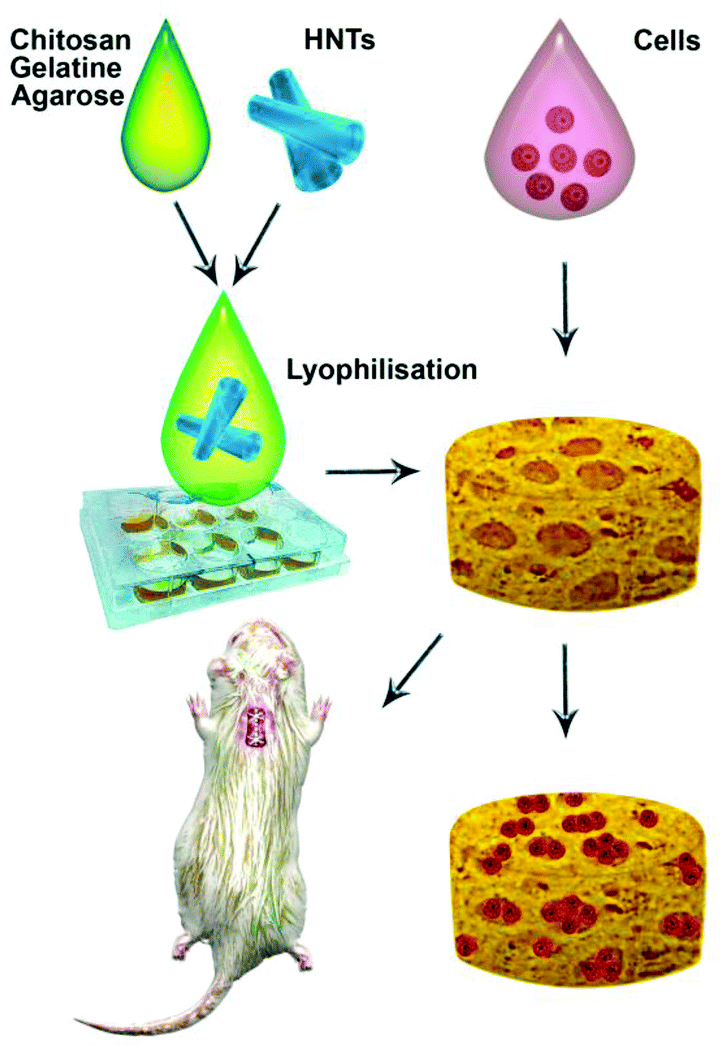 | ||
| Fig. 1 A scheme demonstrating the fabrication of halloysite-doped scaffolds and the subsequent biocompatibility assays. | ||
Halloysite-doped biocomposite scaffolds demonstrate extraordinary cell growth
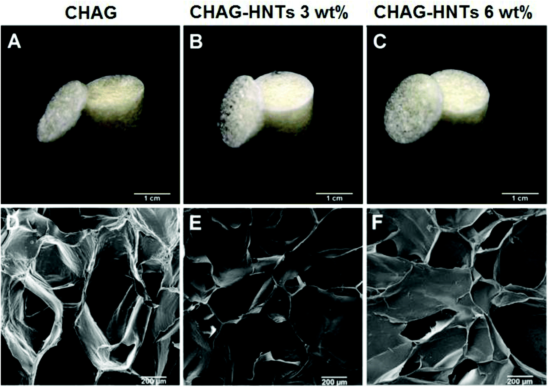 | ||
| Fig. 2 Photographs demonstrating the morphology of pillar-shaped porous scaffolds (A–C); SEM images of CHAG, CHAG–HNT (3 wt%), CHAG–HNT (6 wt%) scaffolds without cells (D–F). | ||
Cell growth and viability testing
We employed two types of human cancer cells (A549 and Hep3B) to estimate the biocompatibility of biocomposite scaffolds in vitro. The cells were seeded on the porous scaffolds providing a suitable growth support for effective cell proliferation. A combination of FDA and DAPI dyes along with the confocal visualization was employed to demonstrate the distribution of cells on the scaffolds. SEM and confocal imaging clearly demonstrate that the cells were grown and spread on the walls of the pores (Fig. 3) and they retained the characteristic cellular morphology. As shown in confocal images, the cells are evenly distributed on the surfaces of the scaffolds, demonstrating the monolayer growth of both A549 and Hep3B. We also employed 3D reconstruction imaging (using CLSM Z-stacking) to demonstrate the spatial distribution of cells inside the matrix pores (Video 1 in the ESI†).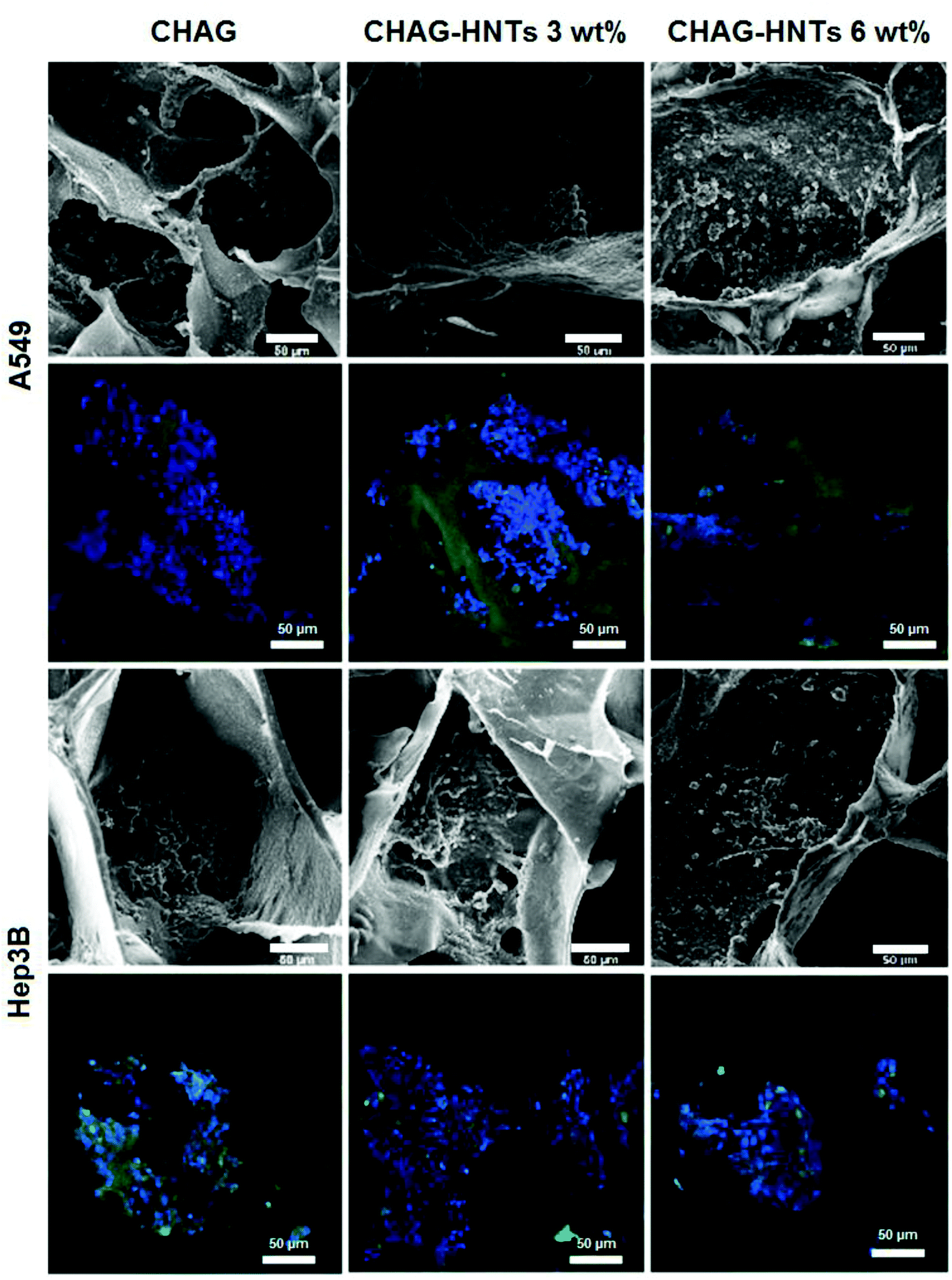 | ||
| Fig. 3 SEM and confocal images of A549 and Hep3B cell distribution on porous 3D scaffolds. | ||
To demonstrate the normal cell morphology and ability to spread on the surface during the growth, we employed F-actin cytoskeleton staining (Fig. 4). Different cell lines were used to estimate the biocompatibility of scaffolds for the wide range of cell cultures. As a result, we demonstrate here that the porous halloysite-hydrogel scaffolds are suitable for at least several varying cell cultures and did not affect the cytoskeleton formation during the cell growth which allows for cell attachment and distribution on the scaffold surface. This finding is exceptionally important for the practical use of the scaffolds in vivo, since the effective attachment of the cells plays an important role in surface colonisation and tissue growth.
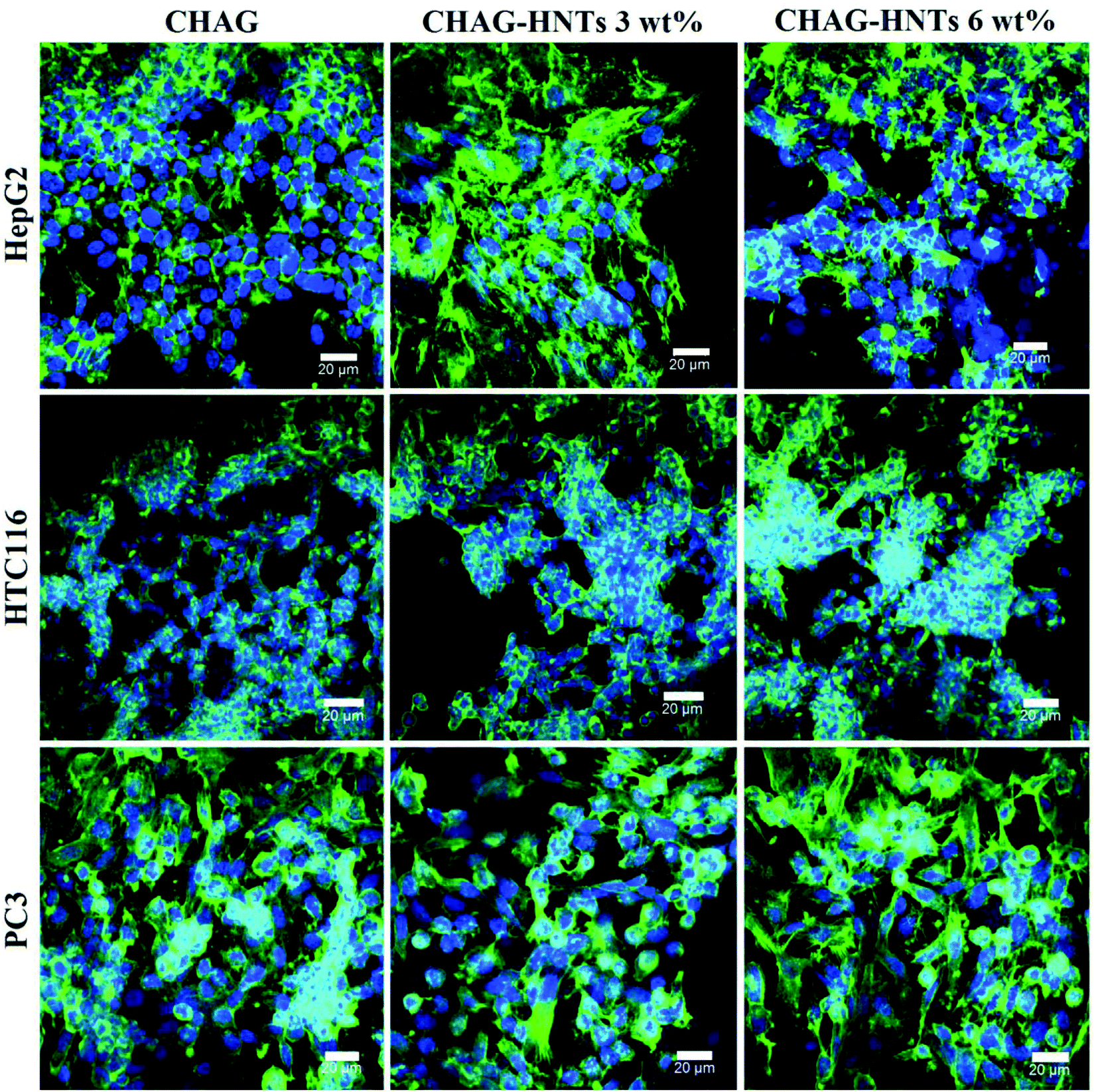 | ||
| Fig. 4 The confocal images demonstrating the F-actin distribution in cells cultivated on porous scaffolds. Cell nuclei are stained with DAPI (blue), and A488-conjugated phalloidin (green) was used to stain F-actin. | ||
Next, we performed a slightly modified in situ MTT test to demonstrate the viability, proliferation and distribution of cells on the halloysite scaffolds. Typically, the procedure is based on measuring the optical density of the purple formazan produced as a result of MTT reduction by live and metabolically active cells. The numerical values of optical density correspond to the number of viable cells.50 Here, however, we resorted on the qualitative demonstration based on the incubation of cell-coated scaffolds with MTT in cell culture plates (Fig. 5). After incubation, the formazan crystals had been transformed by living cells grown on scaffolds yielding dark purple solution if compared with cell-free scaffolds.
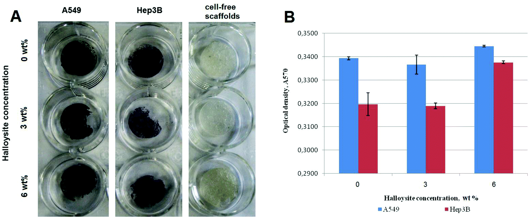 | ||
| Fig. 5 A – MTT assay results of A549 and Hep3B in growth medium seeded on CHAG scaffolds with and without halloysite. The legend indicates the halloysite concentrations. Dark purple staining indicates the metabolic active cell distribution onto scaffolds. B – the results of resazurin assay demonstrating the influence of different scaffold compositions on mitochondrial enzyme activity. | ||
Along with the MTT test, we have used the resazurin (Alamar Blue) assay to demonstrate the viability of cells growing on scaffolds (pure and halloysite-doped). This method allows for confirming the spreading and metabolic activity of cells on the scaffolds. The test is based on the metabolic activity of mitochondria reducing the blue dye resazurin to the pink dye resorufin.51 The resazurin assay demonstrated only a slight decrease of the metabolic activity of cells seeded on scaffolds with 6 wt% of halloysite.
Characterization of the mechanical properties of the scaffolds
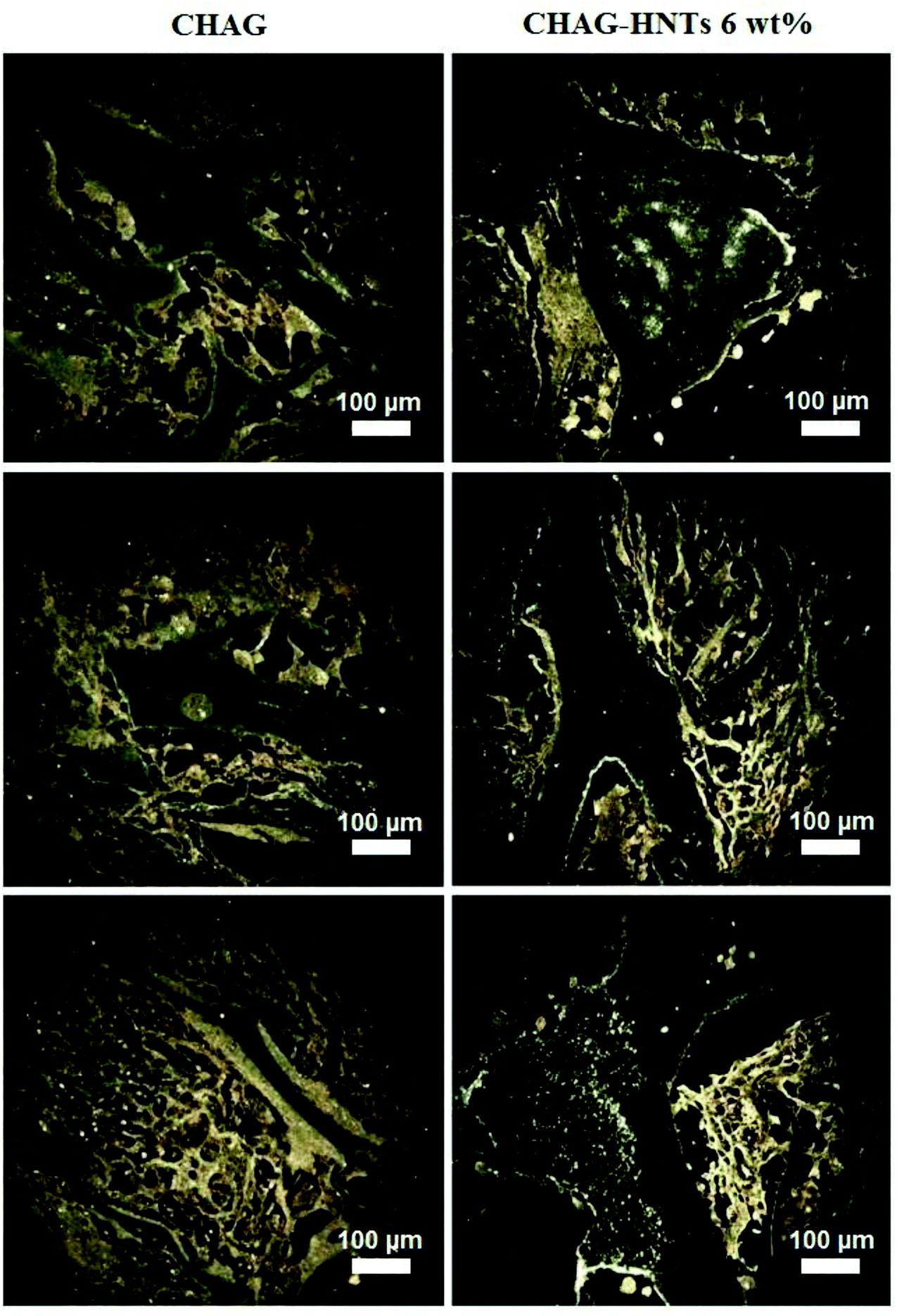
Mechanical stability, flexibility and elasticity of the tissue engineering scaffolds are of great importance because the structural stability is essential to withstand stresses incurred during in vitro cultivation and in vivo implantation. Macroscopic observations have confirmed that all the samples of scaffolds exhibited the sponge-like behaviour with the shape memory and shape reconstitution after deformation both in wet and dry states. Atomic force microscopy was applied to demonstrate the incorporation of halloysite nanotubes into the polymer matrix (Fig. 6A–H), also confirming that the incorporation of nanotubes increases the surface roughness of the scaffold surfaces. Apparently SEM imaging did not allow visualising the matrix-embedded nanotubes because of the sputter-coating applied prior to imaging, whereas the direct AFM imaging in PeakForce Tapping® mode allowed resolving the single nanotubes positioned close to the scaffold surface. To further investigate the mechanical properties of the scaffolds obtained, we applied Dynamic Mechanical Analysis (DMA). Using a DMA analyser, we have investigated the elasticity of biocomposite scaffolds as one of the most important mechanical parameter for biopolymer matrixes. Adding halloysite into scaffold composition caused minimal changes in structural features but significantly influenced the elastic modulus (E′) behaviour of materials and consequently the mechanical strength and thermostability. Fig. 6C, F and I show the temperature scans obtained by DMA. The first peak of the elastic modulus of CHAG, when exposed to a frequency of 1 Hz, is observed at 37.6 °C and centred around 2.850 MPa (Fig. 6C). With increasing temperature, we observed the rise of the elastic modulus; local maxima (3.136 MPa and 3.249 MPa) coincided with a proportional reduction in the dielectric loss tangent (tanσ). Within the studied temperature range, we observed the increase of the dielectric properties of the sample and its heat resistance. Heating of HNT-doped samples (Fig. 6F) from 42.2 °C to 75.9 °C leads to a significant increase of the elastic modulus. The second peak of the elastic modulus (at 87.2°) coincides with the lowest tanσ in the temperature range from 50 to 100 °C.
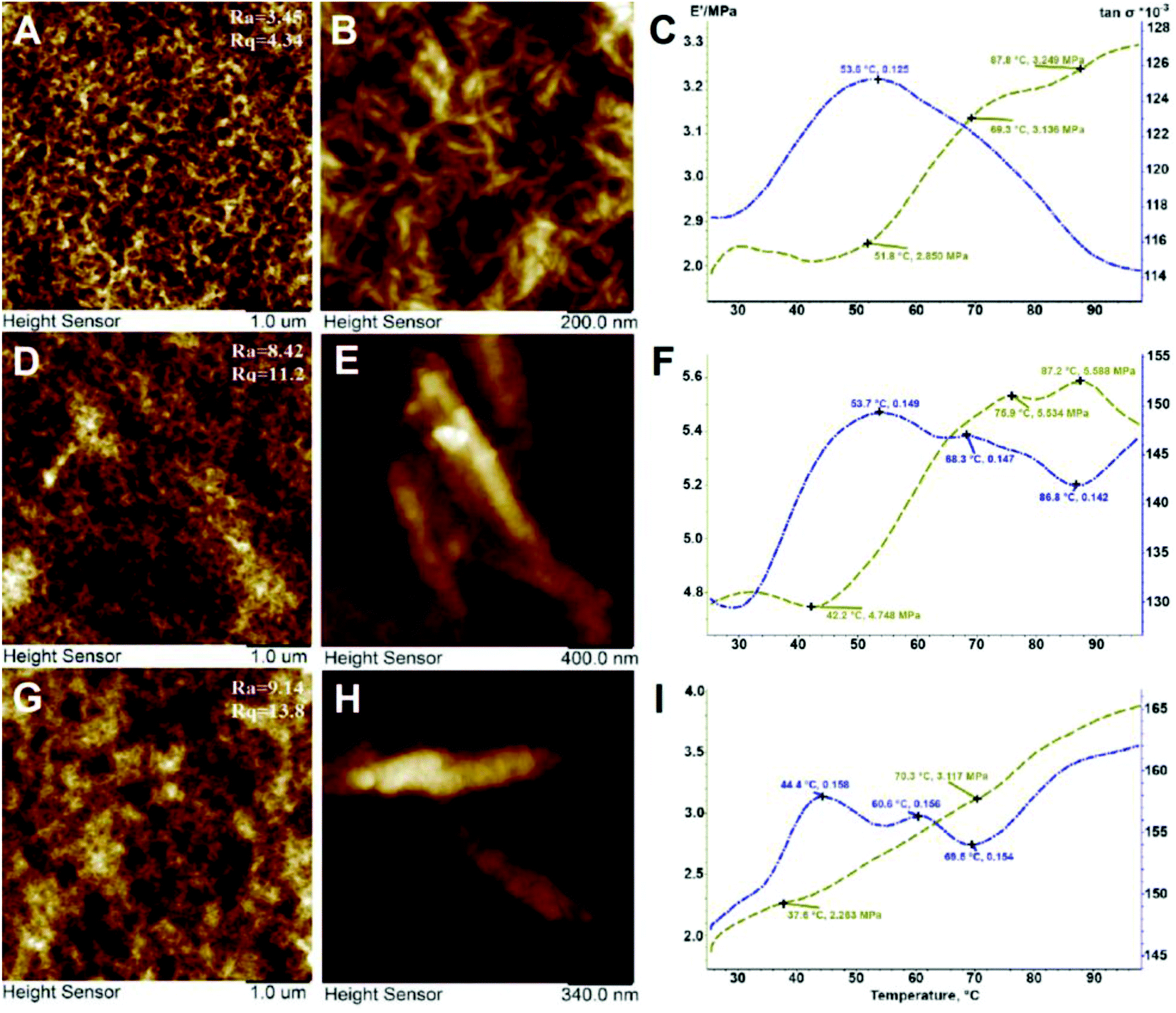 | ||
| Fig. 6 DMA analysis and AFM imaging of CHAG (A–C), CHAG–HNT 3 wt% (D–F) and CHAG–HNT 6 wt% (G–I). Note the HNTs visible in higher-magnification AFM images (E, H). | ||
The increasing value of the elastic modulus of the samples is due to their sintering or glass transition, while the decrease of the elastic modulus shows melting or destruction of the sample and reduction of the dielectric properties. In addition, we performed the tensile strength testing of the composite scaffolds. We have revealed that halloysite addition leads to an increase of the Young's modulus and thus the tensile strength of the samples with halloysite is higher than that of the pure biopolymer scaffold (Table 1).
| Sample | Peak load (MPa), ±10% | Young's modulus (MPa), ±10% |
|---|---|---|
| Control | 0.5 | 6.5 |
| CHAG–HNTs 3 wt% | 1.0 | 8.0 |
| CHAG–HNTs 6 wt% | 1.5 | 9.0 |
The strength of the samples studied was compared to that of a cellulose sample, which has been characterised by Xing et al.3 The samples described in this work endured a peak load of 20 MPa and had a Young's modulus of 330 MPa. The highest peak load and Young's modulus of our current samples are 1.5 and 9 MPa which indicates that these samples are softer than the ones made from cellulose (cellulose microfibers taken from raw paper are very long, ∼1–2 mm). This could make the sample suitable for placing in biological tissues.
The FTIR spectra of pristine halloysite and CHAG–HNTs (6 wt%) are shown in Fig. 1. The peak at 3694 cm−1 and 3622 cm−1 can be assigned to the O–H stretching vibration of the inner-surface Al–OH groups and inner Al–OH groups between the interface of the Si–O tetrahedron and the Al–O octahedron in halloysite. The stretching vibration of the Si–O network corresponds to the peak at 1026 cm−1. Despite the low concentration of halloysite and interference from other components, the peaks for each of the elements can be seen in the experimental samples.
Water uptake (swelling properties)
Swelling properties during liquid uptake by the scaffolds can indicate the diffusion, adsorption and exchange of nutrients and waste throughout the entire scaffold. Chitosan is a hydrophilic substance due to an abundant number of hydrophilic groups which can promote water uptake in the structure.52 The water uptake ability was evaluated by embedding of dry scaffolds in distilled water at 37 °C for 72 h (Fig. 7B).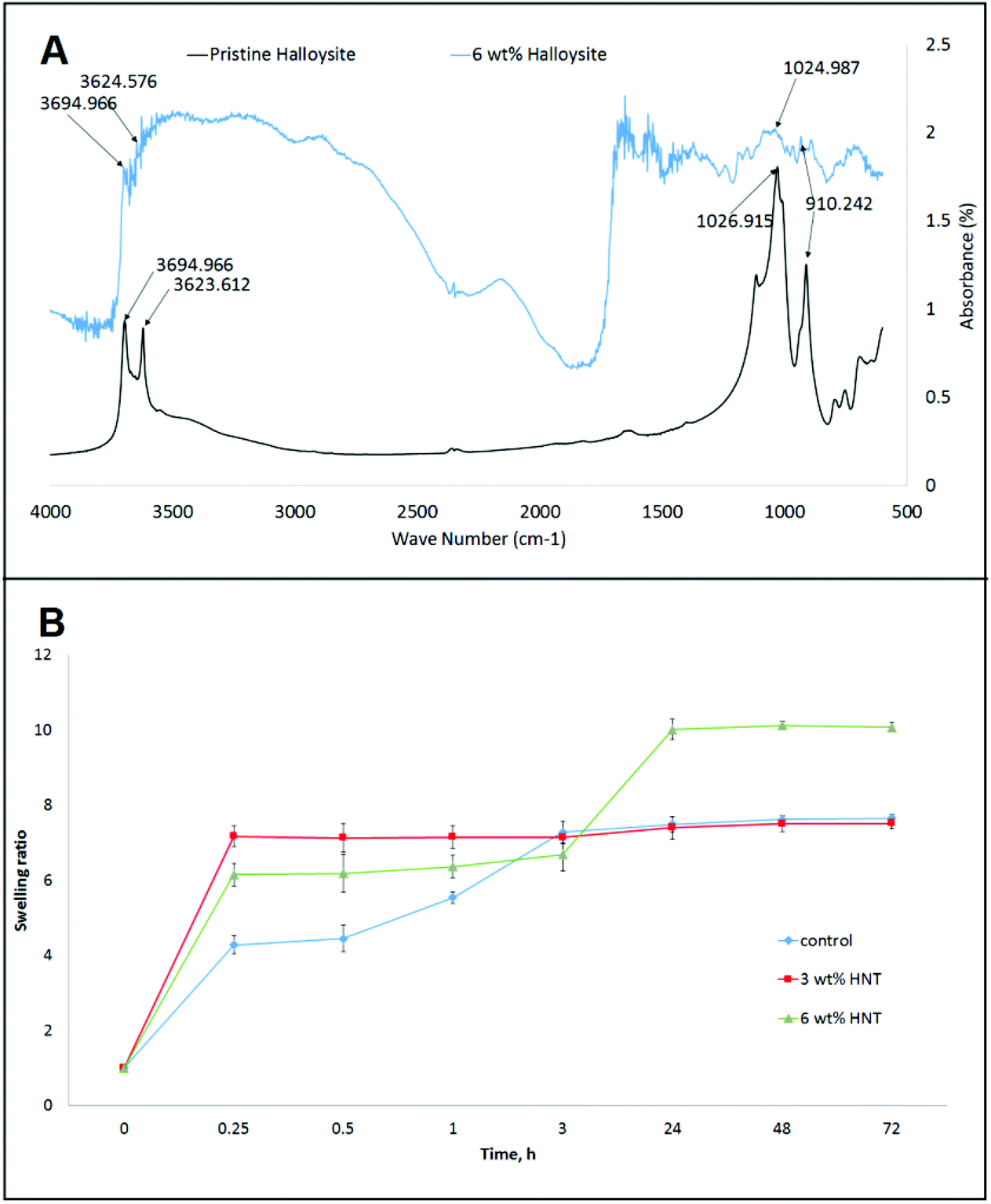 | ||
| Fig. 7 A – FTIR spectra of pristine halloysite and CHAG–HNTs (6 wt%); B – swelling properties of CHAG (0 wt%), CHAG-HNT (3 wt%), and CHAG–HNT (6 wt%) scaffolds. | ||
Doping the scaffolds with halloysite has significantly affected the swelling properties. In the first 15 min all the samples increased their weight by 4–7.5 fold. In the case of the control scaffold without the addition of halloysite, this rapid weight increase elongated up to 3 h. Then during the last 69 h the swelling ratio of the control sample was stabilized. The scaffold with 3 wt% halloysite showed the fastest water uptake but the resulting swelling ratio was identical to the control. The water uptake behaviour of the samples with the highest concentration of halloysite was different from that demonstrating the secondary increase of the weight between 3 and 24 h of the experiment. This phenomenon might be caused by the slow water uptake by the inner lumens of nanotubes. The swelling experiments indicated that the addition of halloysite can greatly improve the hydrophilicity and wetting of composite scaffolds. The incorporation of halloysite nanotubes into the scaffolds increases the water uptake and subsequently improves the biocompatibility. The intrinsic properties of halloysite nanotubes can be used for further improving the biocompatibility of scaffolds by the loading and sustained release of different bioactive compounds. This opens the prospect for fabrication of scaffolds with defined properties for directed differentiation of cells on matrixes due to gradual release of differentiation factors.
In vivo analysis of scaffolds’ biocompatibility
The halloysite-free and doped with 6 wt% of halloysite scaffolds were implanted subcutaneously into rats (Fig. 8A–C). After 3 and 6 weeks after implantation, the rats were euthanized and histological sections were prepared from biopsies of all major organs (brain, kidney, liver, heart, spleen, lymph nodes, testicles) and the newly formed tissue surrounded the implanted scaffold. During the entire period of the experiment, no rejection was observed and the surgery wound in all experimental groups was healed on the 7th day. Histologically the scaffold material represented as a mesh substance with a foreign irregular structure which is located directly under the beams of the subcutaneous muscle and stained with eosin (Fig. 8D).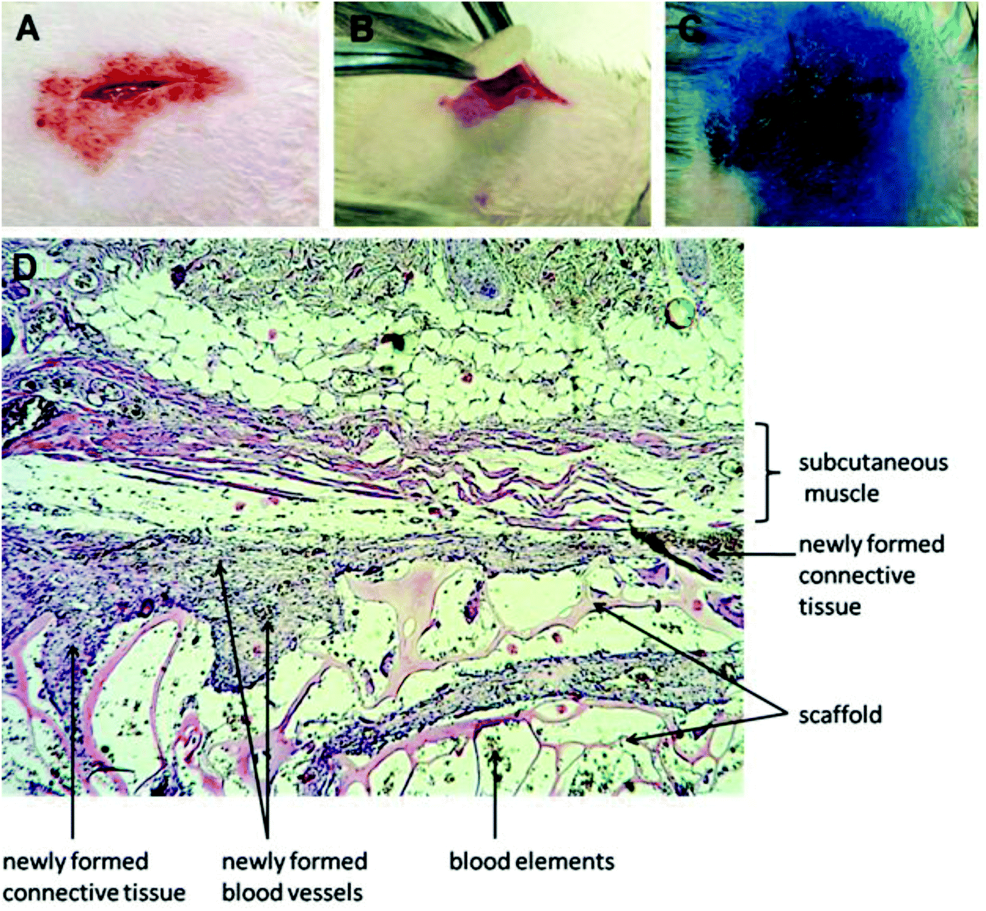 | ||
| Fig. 8 A scheme of the cell-free scaffold subcutaneous implantation (A – incision, B – scaffold implantation, C – suture treated with brilliant green). D – a general view of the subcutaneous peri-implant area after 3 weeks after transplantation indicating the scaffold disposition and new formation of connective tissue and blood vessels. | ||
After 3 weeks upon implantation, the overgrowth of the scaffold material with connective tissue was observed as the young granulation with moderate lymphohistiocytic infiltration. The granulations by separate strands penetrate into the sponge-like scaffold material with approximately one-third of its thickness. The connective tissue which replaces the substrate is filled with de novo formed blood vessels of different diameters. The pronounced reaction to a foreign body (the increase of giant multinucleated cells of foreign bodies and Langhans cells) after implantation of the scaffolds doped with halloysite was observed, none of which happened after implantation of halloysite-free scaffolds (Fig. 9).
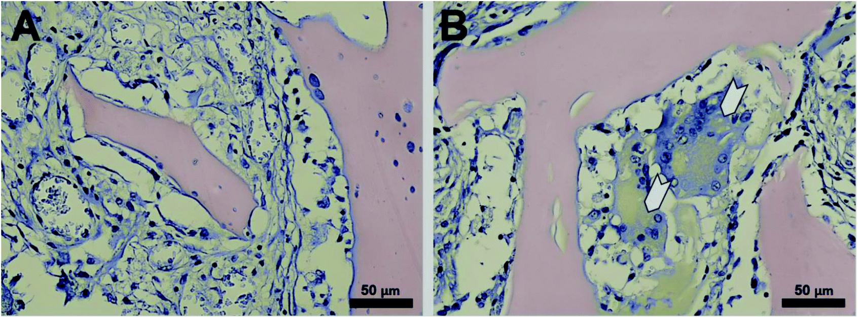 | ||
| Fig. 9 Haematoxylin/eosin staining of CHAG (A) and CHAG–HNT 6 wt% (B) scaffolds (3 weeks after subcutaneous implantation). White arrows indicate the giant multinuclear cells. | ||
Noteworthily, no abnormalities were observed in all major organs in the case of implantation of scaffolds with and without halloysite nanotubes. We employed for the first time, enhanced dark-field microscopy to locate the halloysite nanotube distribution in the area of implantation. A moderate yield of nanotubes into the surrounding newly formed connective tissue bands was detected using dark-field microscopy of unstained histological thin paraffin sections (Fig. 10).
 | ||
| Fig. 10 Enhanced dark-field microscopy of the peri-implant subcutaneous area (different sections). Sections were made after 3 weeks after transplantation. Note the moderate release of halloysite nanotubes into the surrounding tissue. | ||
Soft tissues outside the newly-formed granulations do not exhibit any pronounced inflammatory reaction. Six weeks after implantation of scaffolds, no pathological changes in the internal organs were observed (data not shown). Complete resorption of the scaffold without halloysite has occurred with the growth of the connective tissue (Fig. 11C). The scaffolds with halloysite remained in the form of separate small fragments, the thickness of the fibrous connective tissue capsule decreased, and the lack of multinucleated giant cells was observed (Fig. 11D).
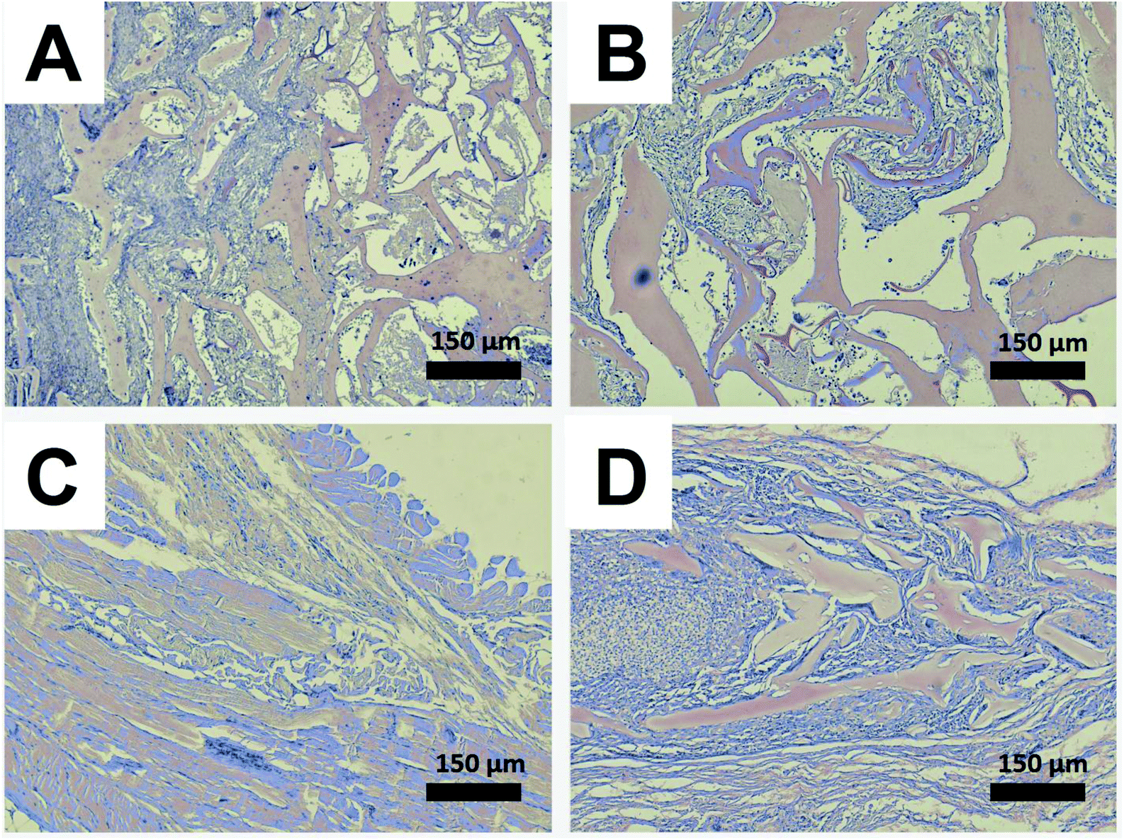 | ||
| Fig. 11 Haematoxylin/eosin staining of the peri-implant area after 3 (A, B) and 6 weeks (C, D) after implantation. Note the complete resorption (C) or dramatic decrease (D) of the scaffold material (eosin-stained). | ||
Formation of blood vessels at the implantation site is crucially important for the effective growth on implants. To determine the blood perfusion in the implantation area, we employed a laser Doppler analyser. During scanning, moving blood cells shift the light frequency according to the Doppler effect. The photodiode of the analyser collects the backscattered light, and the original light intensity variations are transformed into voltage (0–10 V), here the value of 0 V was calibrated as 0% perfusion and 10 V was calibrated as 100%. After scanning, a colour-coded image representing the blood flow distribution was captured. The electrical signal from the blood perfusion was subdivided into six different intervals which displayed as separate colours from dark blue (low or no perfusion) to red (highest perfusion interval). The analysis was performed after 3 and 6 weeks after implantation. Implantation of both types of implants (with and without halloysite) led to reduction in the blood supply to the local area of implantation to a level below 100 APU. However, after 6 weeks, the blood flow was completely restored to normal values above 100 APU (Fig. 12).
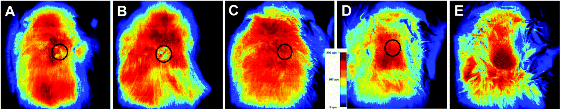 | ||
| Fig. 12 Laser Doppler instrument-images of the implantation area: A – 3 weeks after implantation of CHAG, B – 3 weeks after implantation of CHAG-6 wt% HNTs, C – 6 weeks after implantation of CHAG, D – 6 weeks after implantation of CHAG-6 wt% HNTs, and E – untreated rat. Note the improvement of blood perfusion after 6 weeks after implantation. Black circles indicate the implant area. | ||
Thus, the neo-vascularization observed in the new connective tissue which penetrated the scaffold material indicates that the investigated scaffolds are biocompatible and can induce the formation of new blood vessels (Fig. 8). The results of the transplanted area biopsy demonstrate that the cryogel-formed scaffolds doped with halloysite have a suitable porous interconnected network for the infiltration of the cells from the surrounded tissue or the blood cells. The infiltrative growth of the connective tissue within the implanted scaffold suggests the compatibility of its chemical composition and structure. The lack of well-manifested inflammation and rejection of implants also indicate the immunological biocompatibility of the scaffolds and thus suggest the possibility of their use as cell carriers for artificial tissue formation. The varying rate of scaffold resorption depending on the presence of nanotubes allows modulating the properties that can be used in the development of various tissue-engineering structures, mimicking a great variety of body tissues. Taking into account the shape memory of chitosan constructs52 and the mechanical reinforcement outlined by halloysite nanotubes,53 the scaffolds fabricated in this paper will be potentially well internalised in real applications.
Conclusion
We employed here the freeze-dry technology for fabrication of porous biopolymer hydrogels doped with halloysite nanotubes and demonstrated the biocompatibility and biodegradability of the resulting scaffolds in vitro and in vivo. We have demonstrated the enhancement of mechanical properties, biocompatibility and biodegradability of porous hydrogel scaffolds containing clay nanotubes. The addition of 3–6 wt% of halloysite nanotubes leads to a significant improvement of mechanical stability and wettability of the biopolymer scaffolds without harming the cell growth in vitro. The cell distribution and morphology showed that cells can be attached and grown well on halloysite-scaffolds. The in vivo study has shown the biocompatibility of these nanocomposite scaffolds in the organism of rats with a slight inflammatory effect without rejection of implants and with a 6 week period of degradation that was confirmed by histological examination. We have estimated the blood perfusion in the implanted area and observed the full restoration of blood supply in six weeks. These results confirm the great potential of chitosan–agarose–gelatine nanocomposite porous scaffolds doped with halloysite in tissue engineering with potential for sustained nanotube drug delivery.Author contributions
The manuscript was written through contributions of all authors. All authors have given their approval to the final version of the manuscript.Acknowledgements
The work is performed according to the Russian Government Program of Competitive Growth of Kazan Federal University. This work was funded by the subsidy allocated to Kazan Federal University for the state assignment in the sphere of scientific activities. The authors acknowledge the support by the RFBR grant 15-34-20583 mol_a_ved. YL thanks the National Science Foundation #1547693 for partial support of this work. Any opinions, findings, and conclusions or recommendations expressed in this report are those of authors and do not necessarily reflect the view of the National Science Foundation. Authors acknowledge the CRDF Global Award FSCX-15-61829-0 from the U.S. Civilian Research & Development Foundation (CRDF Global). Any opinions, findings and conclusions or recommendations expressed in this material are those of the authors and do not necessarily reflect the views of CRDF Global. Authors thank Dr M. DeCoster for useful discussions, Mr E. Nuzhdin for help with scanning electron microscopy, Ms A. Dubkova for technical help with figures.References
- J. C. Robins, J. R. Morgan, P. Krueger and S. A. Carson, Bioengineering Anembryonic Human Trophoblast, Reprod. Sci., 2011, 18, 128–135 CrossRef PubMed.
- G. Chen, T. Ushida and T. Tateishi, Scaffold Design for Tissue Engineering, Macromol. Biosci., 2002, 2, 67–77 CrossRef CAS.
- Q. Xing, S. Chen, F. Zhao, M. DeCoster and Y. Lvov, Porous Biocompatible Three Dimensional Scaffolds of Cellulose Microfiber/Gelatin Composites for Cell Culture, Acta Biomater., 2010, 6, 2132–2139 CrossRef CAS PubMed.
- C. J. E. Watson and J. H. Dark, Organ Transplantation: Historical Perspective and Current Practice, Br. J. Anaesth., 2012, 108(suppl 1), i29–i42 CrossRef PubMed.
- S. V. Murphy and A. Atala, 3D Bioprinting of Tissues and Organs, Nat. Biotechnol., 2014, 32, 773–785 CrossRef CAS PubMed.
- M. M. Hanasono and R. J. Skoracki, Computer-assisted Design and Rapid Prototype Modeling in Microvascular Mandible Reconstruction, Laryngoscope, 2013, 123, 597–604 CrossRef PubMed.
- S. N. Bhatia, G. H. Underhill, K. S. Zaret and I. J. Fox, Cell and Tissue Engineering for Liver Disease, Sci. Transl. Med., 2014, 6, 245sr2 CrossRef PubMed.
- A. Atala, Tissue Engineering of Human Bladder, Br. Med. Bull., 2011, 97, 81–104 CrossRef PubMed.
- X. Gu, F. Ding and D. F. Williams, Neural Tissue Engineering Options for Peripheral nerve Regeneration, Biomaterials, 2014, 35, 6143–6156 CrossRef CAS PubMed.
- R. V. Shevchenko, S. L. James and S. E. James, A Review of Tissue-Engineered Skin Bioconstructs Available for Skin Reconstruction, J. R. Soc., Interface, 2010, 7, 229–258 CrossRef CAS PubMed.
- A. R. Amini, C. T. Laurencin and S. P. Nukavarapu, Bone Tissue Engineering: Recent Advances and Challenges, Crit. Rev. Biomed. Eng., 2012, 40, 363–408 CrossRef PubMed.
- L. Kock, C. C. van Donkelaar and K. Ito, Tissue Engineering of Functional Articular Cartilage: the Current Status, Cell Tissue Res., 2012, 347, 613–627 CrossRef CAS PubMed.
- C. T. Laurencin and J. W. Freeman, Ligament Tissue Engineering: An Evolutionary Materials Science Approach, Biomaterials, 2005, 26, 7530–7536 CrossRef CAS PubMed.
- Y. Whulanza, E. Battini, L. Vannozzi, M. Vomero, A. Ahluwalia and G. J. Vozzi, Electrical and Mechanical Characterisation of Single Wall Carbon Nanotubes Based Composites for Tissue Engineering Applications, Nanosci. Nanotechnol., 2013, 1, 188–197 CrossRef.
- P. E. Mikael, A. R. Amini, J. Basu, M. Josefina Arellano-Jimenez, C. T. Laurencin, M. M. Sanders, C. Barry Carter and S. P. Nukavarapu, Functionalized Carbon Nanotube Reinforced Scaffolds for Bone Regenerative Engineering: Fabrication, in vitro and in vivo Evaluation, Biomed. Mater., 2014, 3, 035001, DOI:10.1088/1748-6041/9/3/035001.
- M. Mattioli-Belmonte, G. Vozzi, Y. Whulanza, M. Seggiani, V. Fantauzzi, G. Orsini and A. Ahluwalia, Tuning Polycaprolactone – Carbon Nanotube Composites for Bone Tissue Engineering Scaffolds, Mater. Sci. Eng., C, 2012, 32, 152–159 CrossRef CAS.
- K. Ariga, J. Li, J. Fei, Q. Ji and J. P. Hill, Nanoarchitectonics for Dynamic Functional Materials from Atomic-/Molecular-Level Manipulation to Macroscopic Action, Adv. Mater., 2016, 28, 1251–1286 CrossRef CAS PubMed.
- W. Nakanishi, K. Minami, L. K. Shrestha, Q. Ji, J. P. Hill and K. Ariga, Bioactive Nanocarbon Assemblies: Nanoarchitectonics and Applications, Nano Today, 2014, 9, 378–394 CrossRef CAS.
- K. Minami, Y. Kasuya, T. Yamazaki, Q. Ji, W. Nakanishi, J. P. Hill, H. Sakai and K. Ariga, Highly Ordered 1D Fullerene Crystals for Concurrent Control of Macroscopic Cellular Orientation and Differentiation toward Large-Scale Tissue Engineering, Adv. Mater., 2015, 27, 4020–4026 CrossRef CAS PubMed.
- V. E. Tikhonov, E. A. Stepnova, V. G. Babak, I. A. Yamskov, J. Palma-Guerrero, H.-B. Jansson, L. V. Lopez-Llorca, J. Salinas, D. V. Gerasimenko, I. D. Avdienko and V. P. Varlamov, Bactericidal and Antifungal Activities of a Low Molecular Weight Chitosan and Its N-/2(3)-(dodec-2-enyl)succinoyl/-derivatives, Carbohydr. Polym., 2006, 64, 66–72 CrossRef CAS.
- K. Azuma, T. Osaki, S. Minami and Y. Okamoto, Anticancer and Anti-Inflammatory Properties of Chitin and Chitosan Oligosaccharides, J. Funct. Biomater., 2015, 6, 33–49 CrossRef PubMed.
- P. Zhang, W. Liu, Y. Peng, B. Han and Y. Yang, Toll like Receptor 4 (TLR4) Mediates the Stimulating Activities of Chitosan Oligosaccharide on Macrophages, Int. Immunopharmacol., 2014, 23, 254–261 CrossRef CAS PubMed.
- J. Zhu and R. E. Marchant, Design Properties of Hydrogel Tissue-Engineering Scaffolds, Expert Rev. Med. Devices, 2011, 8, 607–626 CrossRef CAS PubMed.
- M. Okamoto and B. John, Synthetic Biopolymer Nanocomposites for Tissue Engineering Scaffolds, Prog. Polym. Sci., 2013, 38, 1487–1503 CrossRef CAS.
- M. Liu, C. Wu, Y. Jiao, S. Xiong and C. Zhou, Chitosan–Halloysite Nanotubes Nanocomposite Scaffolds for Tissue Engineering, J. Mater. Chem. B, 2013, 1, 2078–2089 RSC.
- X. M. Sun, Y. H. Zhang, B. Shen and N. Q. Jia, Direct Electrochemistry and Electrocatalysis of Horseradish Peroxidase Based on Halloysite Nanotubes/Chitosan Nanocomposite film, Electrochim. Acta, 2010, 56, 700–705 CrossRef CAS.
- Y. Zheng and A. Wang, Enhanced Adsorption of Ammonium Using Hydrogel Composites Based on Chitosan and Halloysite, J. Macromol. Sci., Part A: Pure Appl. Chem., 2010, 47, 33–38 CrossRef CAS.
- R. T. De Silva, P. Pasbakhsh, K. L. Goh, S.-P. Chai and H. Ismail, Physico-Chemical Characterisation of Chitosan/Halloysite Composite Membranes, Polym. Test., 2013, 32, 265–271 CrossRef CAS.
- E. Abdullayev and Y. Lvov, Halloysite Clay Nanotubes as a Ceramic “skeleton” for Functional Biopolymer Composites with Sustained Drug Release, J. Mater. Chem. B, 2013, 1, 2894–2903 RSC.
- C. S. C. Chiewa, P. E. Poh, P. Pasbakhsh, B. T. Tey, H. K. Yeoh and E. S. Chan, Physicochemical Characterization of Halloysite/Alginate Bionanocomposite Hydrogel, Appl. Clay Sci., 2014, 101, 444–454 CrossRef.
- G. Cavallaro, G. Lazzara, S. Konnova, R. Fakhrullin and Y. Lvov, Composite Films of Natural Clay Nanotubes with Cellulose and Chitosan, Green Mater., 2014, 2, 232–242 CrossRef.
- T. G. Shutava, R. F. Fakhrullin and Y. M. Lvov, Spherical and Tubule Nanocarriers for Sustained Drug Release, Curr. Opin. Pharmacol., 2014, 18, 141–148 CrossRef CAS PubMed.
- W. Wei, R. T. Minullina, E. Abdullayev, R. F. Fakhrullin, D. Mills and Y. M. Lvov, Enhanced Efficiency of Antiseptics with Sustained Release from Clay Nanotubes, RSC Adv., 2014, 4, 488–494 RSC.
- M. R. Dzamukova, E. A. Naumenko, Y. M. Lvov and R. F. Fakhrullin, Enzyme-activated intracellular drug delivery with tubule clay nanoformulation, Sci. Rep., 2015, 5, 10560, DOI:10.1038/srep10560.
- Y. M. Lvov, A. Aerov and R. F. Fakhrullin, Clay Nanotube Encapsulation for Functional Biocomposites, Adv. Colloid Interface Sci., 2014, 207, 189–198 CrossRef CAS PubMed.
- Y. Lvov, W. Wang, L. Zhang and R. Fakhrullin, Halloysite Clay Nanotubes for Loading and Sustained Release of Functional Compounds, Adv. Mater., 2015, 28, 1227–1250 CrossRef PubMed.
- A. Abarrategi, M. C. Gutiérrez, C. Moreno-Vicente, M. J. Hortigüela, V. Ramos, J. L. López-Lacomba, M. L. Ferrer and F. del Monte, Multiwall Carbon Nanotube Scaffolds for Tissue Engineering Purposes, Biomaterials, 2008, 29, 94–102 CrossRef CAS PubMed.
- Y. Zhao, S. Wang, Q. Guo, M. Shen and X. Shi, Hemocompatibility of Electrospun Halloysite Nanotube- and Carbon Nanotube-Doped Composite Poly(lactic-co-glycolic acid) Nanofibers, Appl. Polym. Sci., 2013, 127, 4825–4832 CrossRef CAS.
- C. A. Poland, R. Duffin, I. Kinloch, A. Maynard, W. A. Wallace, A. Seaton, V. Stone, S. Brown, W. Macnee and K. Donaldson, Carbon Nanotubes Introduced into the Abdominal Cavity of Mice Show Asbestos-Like Pathogenicity in a Pilot Study, Nat. Nanotechnol., 2008, 3, 423–428 CrossRef CAS PubMed.
- G. I. Fakhrullina, F. S. Akhatova, Y. M. Lvov and R. F. Fakhrullin, Toxicity of halloysite clay nanotubes in vivo: a Caenorhabditis elegans study, Environ. Sci.: Nano, 2015, 2, 54–59 RSC.
- S. A. Konnova, I. R. Sharipova, T. A. Demina, Y. N. Osin, D. R. Yarullina, O. N. Ilinskaya, Y. M. Lvov and R. F. Fakhrullin, Biomimetic Cell-Mediated Three-Dimensional Assembly of Halloysite Nanotubes, Chem. Commun., 2013, 49, 4208–4210 RSC.
- V. Vergaro, E. Abdullayev, Y. Lvov, A. Zeitoun, R. Cingolani and S. Leporatti, Cytocompatibility and Uptake of Halloysite Clay Nanotubes, Biomacromolecules, 2010, 11, 820–829 CrossRef CAS PubMed.
- D. Lu, H. Chen, J. Wu and C. M. Chan, Direct Measurements of the Young's Modulus of a Single Halloysite Nanotube Using a Transmission Electron Microscope with a Bending Stage, J. Nanosci. Nanotechnol., 2011, 11, 7789–7793 CrossRef CAS PubMed.
- L. Guimarães, A. N. Enyashin, G. Seifert and H. A. Duarte, Structural, Electronic, and Mechanical Properties of Single-Walled Halloysite Nanotube Models, J. Phys. Chem. C, 2010, 114, 11358–11363 Search PubMed.
- M. Liu, B. Guo, Q. Zou, M. Du and D. Jia, Interactions between Halloysite Nanotubes and 2,5-bis(2-benzoxazolyl) Thiophene and Their Effects on Reinforcement of Polypropylene/Halloysite Nanocomposites, Nanotechnology, 2008, 19, 205709 CrossRef PubMed.
- M. Liu, B. Guo, M. Du and D. Jia, The Role of Interactions between Halloysite Nanotubes and 2,2′-(1,2-Ethenediyldi-4,1-phenylene) Bisbenzoxazole in Halloysite Reinforced Polypropylene Composites, Polym. J., 2008, 40, 1087–1093 CrossRef CAS.
- H. Ismail, P. Pasbakhsh, A. M. N. Fauzi and A. Abu Bakar, Morphological, Thermal and Tensile Properties of Halloysite Nanotubes Filled Ethylene Propylene Diene Monomer (EPDM) Nanocomposites, Polym. Test., 2008, 27, 841–850 CrossRef CAS.
- R. D. Cardiff, C. H. Miller and R. J. Munn, Manual Hematoxylin and Eosin Staining of Mouse Tissue Sections, Cold Spring Harb. Protoc., 2014, 6, 655–658 Search PubMed.
- M. Liu, Y. Shen, P. Ao, L. Dai, Z. Liu and Ch. Zhou, The Improvement of Hemostatic and Wound Healing Property of Chitosan by Halloysite Nanotubes, RSC Adv., 2014, 4, 23540–23553 RSC.
- M. V. Berridge and A. S. Tan, Characterization of the Cellular Reduction of 3-(4,5-dimethylthiazol-2-yl)-2,5-diphenyltetrazolium bromide (MTT): Subcellular Localization, Substrate Dependence, and Involvement of Mitochondrial Electron Transport in MTT Reduction, Arch. Biochem. Biophys., 1993, 303, 474–482 CrossRef CAS PubMed.
- S. A. Ahmed, R. M. Gogal and J. E. Walsh, A New Rapid and Simple Nonradioactive Assay to Monitor and Determine the Proliferation of Lymphocytes: An Alternative to [3H] Thymidine Incorporation Assays, J. Immunol. Methods, 1994, 170, 211–224 CrossRef CAS PubMed.
- C. O. Correia, S. G. Caridade and J. F. Mano, Chitosan Membranes Exhibiting Shape Memory Capability by the Action of Controlled Hydration, Polymers, 2014, 6, 1178–1186 CrossRef.
- S. C. Olugebefola, A. R. Hamilton, D. J. Fairfield, N. R. Sottos and S. R. White, Structural reinforcement of microvascular networks using electrostatic layer-by-layer assembly with halloysite nanotubes, Soft Matter, 2014, 10, 544–548 RSC.
Footnotes |
| † Electronic supplementary information (ESI) available. See DOI: 10.1039/c6nr00641h |
| ‡ These authors contributed equally to this study. |
| This journal is © The Royal Society of Chemistry 2016 |