
 Open Access Article
 This Open Access Article is licensed under a
 Creative Commons Attribution 3.0 Unported Licence
Colloidal synthesis of pure CuInTe2 crystallites based on the HSAB theory†
N.
Ntholeng
a,
B.
Mojela
a,
S.
Gqoba
a,
M.
Airo
a,
S.
Govindraju
ab,
M. J.
Moloto
c,
J.
Van Wyk
a and
N.
Moloto
*ab
aMolecular Sciences Institute, School of Chemistry, University of the Witwatersrand, Private Bag X3, Johannesburg, 2050, South Africa. E-mail: Nosipho.Moloto@wits.ac.za
bMaterials for Energy Research Group, University of the Witwatersrand, Private Bag 3, Wits, 2050, Republic of South Africa
cDepartment of Chemistry, Vaal University of Technology, Private Bag X021, Vanderbijlpark, 1900, Republic of South Africa
First published on 21st October 2016
Abstract
The colloidal method has extensively been used to synthesize ternary and quaternary copper sulfides and selenides. The formation pathway and the crystallization mechanism of these nanostructures have also been investigated. Although tellurides form part of the chalcogenides, little has been reported on them particularly the crystallization mechanism of these nanostructures. Herein, we report on the colloidal synthesis of CuInTe2. Typically reaction temperatures play a vital role in the formation of colloidal nanostructures. At temperatures below 250 °C, no formation of CuInTe2 was seen. At 250 °C formation of CuInTe2 could be observed with formation of binary impurities. A change in the sequence in which precursors were added at 250 °C yielded pure CuInTe2. Therefore starting with InCl3 and elemental Te dissolved in OLA and TOP, respectively, then adding CuCl dissolved in OLA yielded a pure CuInTe2 phase with agglomerated cubic structures. The pure CuInTe2 crystallites had an optical band gap of 1.22 eV in comparison to 0.93 eV of the impure CuInTe2 phase.
1 Introduction
With increasing interest in fabricating low cost photovoltaic devices, much attention has been focused on exploiting the use of Cu–III–IV2 chalcopyrite based semiconductor materials as effective light absorber layers in thin-film solar cells.1 This is due to their unique energy band gap and other advantages such as a high absorption coefficient, a high radiation stability, exceptional radiation hardness and defect tolerance.2 Among the various Cu-based ternaries, selenides and sulfides have been well explored.2 Solar-energy conversion efficiencies of about 20% and 12% have already been reported for CuInSe2 and CuInS2 respectively.3 Although CuInSe2 and CuInS2 have been extensively studied not much attention has been paid to studies on tellurides in general and particularly CuInTe2.2CuInTe2 has a direct band gap in the range of 0.92 to 1.06 eV and an absorption coefficient of more than 105 cm−1 near the band edge.4 It exhibits a stronger quantum confinement effect and a larger Bohr radius than CuInS2 and CuInSe2, owing to the covalent properties of tellurium.5 Though CuInTe2 films have a distinct combination of pertinent characteristics making them suitable for use in solar cells as absorbers, synthesis of these materials involves complex and expensive processes.4 Boustani et al. prepared CuInTe2 films by thermal evaporation from a single source.6 Roy et al. also prepared CuInTe2 films by a three source co-evaporation technique.7 In an attempt to cut costs posed by vacuum based processes, various methods such as solvothermal synthesis, microwave irradiation, polyol synthesis, the silicate matrix method and the conventional colloidal method have been adopted.8,9 Recently, Kim et al. synthesized CuInTe2 particles using the solvothermal method.10 During the synthesis, prolonged reaction times and various temperatures were explored to obtain the materials.10 Contrary to prolonged reaction times, Malik and co-workers reported significantly shorter reaction times for CuInSe2via the colloidal synthesis.11
Crystallization is one of the few most interesting yet mysterious processes; however it is an important process to understand and influences the ease with which a product is obtained. The first and probably the most critical step of crystallization is nucleation. Nucleation refers to the initial formation process of a crystal phase from another phase, usually a liquid, a solution, or a gas phase. Nucleation defines the boundary conditions for a given crystallization system and most likely dictates the following growth process at given temperature and pressure.12 Unfortunately, understanding the nucleation process is a big challenge mostly because of the difficulty to quantitatively determine the size and concentration of the newly formed tiny clusters. Substantial progress made in colloidal synthesis has shown that key controllable parameters such as temperature, reaction time and the use of coordinating or non-coordinating solvents are essential for controlling the nucleation process and will result in the size-tunable properties, morphology, structure and stoichiometry properties which can be used to shift absorption.13 Although colloidal syntheses have been proven to be cheap and efficient for synthesizing Cu–III–IV2 semiconductors, very little work has been reported on the colloidal synthesis of CuInTe2. Herein, a conventional colloidal method was used to synthesize CuInTe2 crystallites. Temperature as a factor that has a big influence on crystallization was studied. In addition, it became evident that the sequence in which the nuclei form was critical; hence the effect of varying the sequence of adding the precursors to the reaction mixture was also studied. The optical properties of the crystallites were determined to estimate their use in photovoltaic applications as absorber layers.
2 Results and discussion
The objective of the study was to synthesize a ternary CuInTe2 semiconductor material via the colloidal method. In addition, the reaction temperature was varied from 190 °C, 220 °C and 250 °C, and the temperature dependent optical and morphological properties of the resultant materials were studied. The crystallization process of the crystallites was also studied by changing the sequence of precursor addition.2.1 Effects of temperature on the formation of CuInTe2
 | ||
| Fig. 1 XRD patterns of crystallites synthesized using method 1 at various temperatures where ◆ = Te phase and ● = Cu5Te3. | ||
This suggested that the reaction temperature was fairly low to facilitate the reaction with the metal salts.10 Similarly Kim et al. also observed a tellurium hexagonal phase at 200 °C which was attributed to a low reaction temperature and the same phase was detected when the reaction was conducted over a prolonged period.10 Formation of tellurium crystallites therefore was indicative of unformed copper and indium ion monomers during the reaction due to unreacted precursors.
As the temperature was further increased to 220 °C, the (111) peak at 32° 2θ became less intense indicating that the formation of a tellurium phase was gradually disappearing. The less intense peak at 29.2° 2θ (PDF#: 00-026-1117) corresponding to the CuInTe2 phase was observed. Tellurium and binary Cu5Te3 phases were predominant. These findings were in agreement with those of Kim et al. who obtained a mixture of CuInTe2 and Te phases after carrying a solvothermal reaction for 6 h.10
At 250 °C, the CuInTe2 chalcopyrite phase was the major phase corresponding to (111) at 28.5° 2θ, (220) at 48° 2θ, (311) 57° 2θ, (222) at 70.3° 2θ and (420) at 78.1° 2θ planes. However, the formation of a secondary phase of Cu5Te3 was also observed. Similar results have been reported in the literature at temperatures of 260 °C and extended reaction times.10,14 Formation of secondary phases can be attributed to the difference in stability or reactivity of Cu1+ and In3+ ions. Based on the Hard and Soft Acid Base (HSAB) theory, Cu1+ is a soft acid while S2−, Se2− and Te2− are known to be soft bases. According to the theory, soft acids will tend to react more readily with soft bases.14,15 In the present study formation of binary tellurium compounds can be attributed to the strong affinity of Cu1+ ions as soft acids for Te2− ions as soft bases. They react fast and form stronger bonds thus hindering bond formation between indium and tellurium.
The Raman spectra of particles synthesized at different temperatures using method 1 are shown in Fig. 2. The acquired spectra of materials synthesized at 190 °C and 220 °C showed two similar peaks at 117 cm−1 and 140 cm−1. The observed peaks were attributed to the A1 and E vibrational modes of tellurium. A slight shift was observed from the reported values of 120 cm−1 and 139 cm−1.16 This slight frequency shift may be due to bond-stretching forces between the nearest-neighbor atoms.17 Furthermore there was a shoulder peak observed at 188 cm−1 assigned to the E mode.16 The Raman spectrum of particles synthesized at 220 °C was similar to those synthesized at 190 °C. The A1 vibrational mode of copper telluride usually observed at 259 cm−1 originating from the motion of the Te atom with the Cu atom was not seen.18 This suggested that there was relatively a small amount of copper telluride particles as compared to tellurium particles. A similar observation was seen in the X-ray diffraction pattern in Fig. 1 where the major peaks were associated with tellurium. The characteristic A1 mode of chalcopyrite at 127 cm−1 due to the in-plane motion of Te atoms with cations at rest was not observed for both materials at 190 °C and 220 °C.19 For particles synthesized at 250 °C, only two peaks were observed. The broad peak was deconvoluted to two peaks located at 129 cm−1 and 149 cm−1. These peaks were attributed to the A1 and B1 vibrational modes of chalcopyrite CuInTe2 respectively.20 The small peak marked as 188 cm−1 was associated with the E vibrational mode of Te.
 | ||
| Fig. 2 Raman spectra of crystallites synthesized using method 1 at various temperatures. | ||
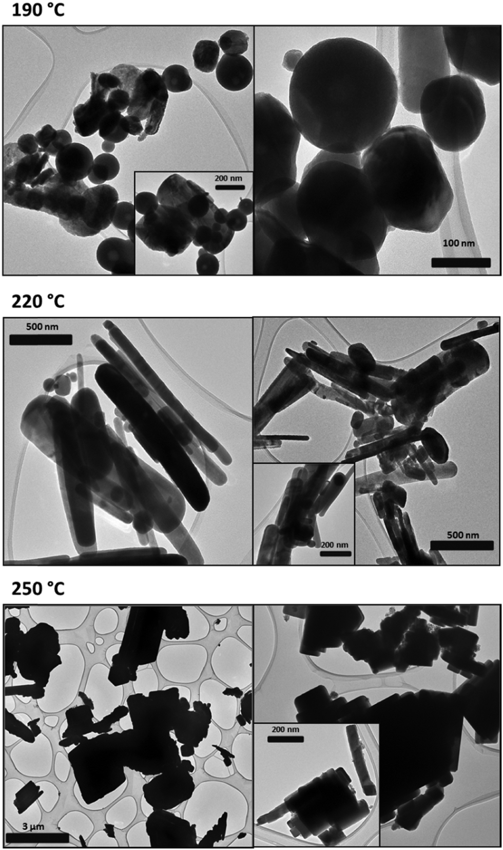 | ||
| Fig. 3 TEM micrographs of crystallites synthesized using method 1 at varying temperatures. The insets are micrographs taken at higher magnifications depicting the morphologies of the crystallites. | ||
2.2 Effects of the order of precursor addition
Previously it has been reported that synthesis of ternary compounds usually yields either binary products or additional phases as impurities and these impurities hinder the use of these materials in any application more so in devices. Recently, Guo et al. demonstrated that the order of precursor addition in CuInSe2 synthesis via a colloidal method is of great importance as it determines the formation pathway of the nanocrystals and allows control over the crystal structure of the particles.21 For instance, chalcopyrite CuInSe2 was formed when all the precursors were added simultaneously whilst the less stable phase of sphalerite was formed when the selenium precursor was injected later at a higher temperature. The consequence of the order/time of precursor addition resulted in particles with different morphologies and properties.21 Herein, it was clear that the ideal temperature was 250 °C as attempted reactions at higher temperatures yielded a cocktail of different compounds. Furthermore, at temperatures higher than 250 °C, OLA began to thermally decomposing. Since Cu5Te3 was still detected at 250 °C, the effect of the order of precursor addition was investigated. The rationale behind this was that based on the HSAB theory, tellurium will always have a higher affinity for copper, hence by tempering with this, it may be possible to eliminate the formation of Cu5Te3. Consequently the indium precursor and the tellurium precursor were first added to allow for them to react. Then the copper precursor was injected at 250 °C and the particles were allowed to grow. This “hot injection” of CuCl induces abrupt supersaturation of the reaction mixture. The supersaturation results in rapid nucleation and growth of the particles which result in the formation of the ternary phase. | ||
| Fig. 4 XRD patterns of CuInTe2 crystallites synthesized at 250 °C using method 1 and 2, where ● = Cu5Te3. | ||
 | ||
| Fig. 5 Raman spectra of CuInTe2 crystallites synthesized at 250 °C using method 1 and 2. | ||
Miller et al. also reported shifts to higher frequencies for HgIn2Te4 chalcopyrite particles.24 The shifts were attributed to the assumption made during calculations that the vacancy–anion force constant was zero however this was later proven to be non-negligible.24 Therefore the shifts to higher frequencies suggested that cation vacancy was not an empty site in the lattice but rather a localized region with a positive potential thereby attracting the valence electrons of the surrounding anions. It was also indicative of the difference in magnitude of vacancy-Te and the Cu–Te stretching force constant.20
At 131 cm−1 the most intense line was observed corresponding to the A1 mode that is due to the motion of Te with Cu and In at rest.25 A weak B1 mode was observed at 149 cm−1 arising from the motion of Cu and In moving in the antiphase.26 This mode was weak due to the change in polarizability resulting from the stretching of the Cu–Te bond compensated by the compression of the In–Te bond.26 The line observed at 149 cm−1 has been previously observed at 148 cm−1 for CuInTe2.20 The highest phonon modes at 216 and 244 cm−1 are attributed to the combination of B2 and E mode.
 | (1) |
 | (2) |
 | (3) |
 | ||
| Fig. 6 UV-Vis-NIR absorption spectra and Kubelka–Munk plot (insets) of CuInTe2 crystallites synthesized at 250 °C using method 1 and 2. | ||
Eqn (3) allows a plot of [F(R) × hν ]1/nversus photon energy hν where n is a constant determined by the nature of the transition that the sample undergoes. The values of n are 1/2, 3/2 and 2 for allowed direct transitions, forbidden direct transitions, and allowed indirect transitions respectively. Because CuInTe2 is known to be a material with a direct band gap,26n is therefore 1/2. By extrapolating a straight line portion of the graph to the hν x-axis, the optical band gap of the material was determined. The deduced optical band gap of the crystallites synthesized by method 1 was 0.93 eV corresponding to the band edge of 1322 nm. The measured absorption spectrum shown in Fig. 6 is however tailing, making it difficult to extract the absorption band edge therefore making the use of the Kubelka–Munk method even more relevant. Nevertheless, the 1322 nm value does agree with reported band gap energy determination from optical absorption measurements and photoconductivity spectra.28 The band gap energy observed is due to the transition of electrons from the shallow acceptor level to the conduction band.29 Shallow acceptor levels have been observed in several Cu–III–VI2 compounds.29
Sridevi et al. reported a band gap of 0.94 eV resulting from the shallow acceptor transitions for CuInTe2 thin films.29 The transitions were attributed to the presence of copper vacancies (Vcu) and antisite defects of indium on copper sites (lncu).29 Contrary to this Wasim et al. argued that shallow acceptor levels were not due to the Cu vacancies rather Te vacancies.30 They argued that if shallow acceptor levels were due to Cu vacancies, the absorption energy of the material with excess Cu and deficient Cu in its stoichiometry would differ which was not the case.30 They attributed the transitions to high hole concentration which has Te vacancies in the material.30 Furthermore, a decrease in the acceptor ionization energy due to the screening effect evidently showed that the shallow acceptor level observed in CulnTe2 is due to Te vacancies.30 This is in agreement with the covalent bonding model under which both the anion interstitials and vacancies should act as acceptors.30 However, in the present case more studies are required to confirm the defect present in the crystallites.
Employing method 2 resulted in an increased band gap of 1.22 eV and the band edge decreased to 1016 nm. This is similar to the reported band gap of 1.26 eV for polycrystalline thin films of CuInTe2.29 The transition is due to spin–orbit interactions in the d level.29 In addition, the increase in the band gap is indicative of smaller crystallite sizes.
 | ||
| Fig. 7 TEM and HRTEM micrographs of CuInTe2 crystallites synthesized at 250 °C using method 2 (a–d) and method 1 (e–h). The insets in (a) and (e) are micrographs at higher magnification and the inset in (h) is a zoomed image depicting the lattice fringes. | ||
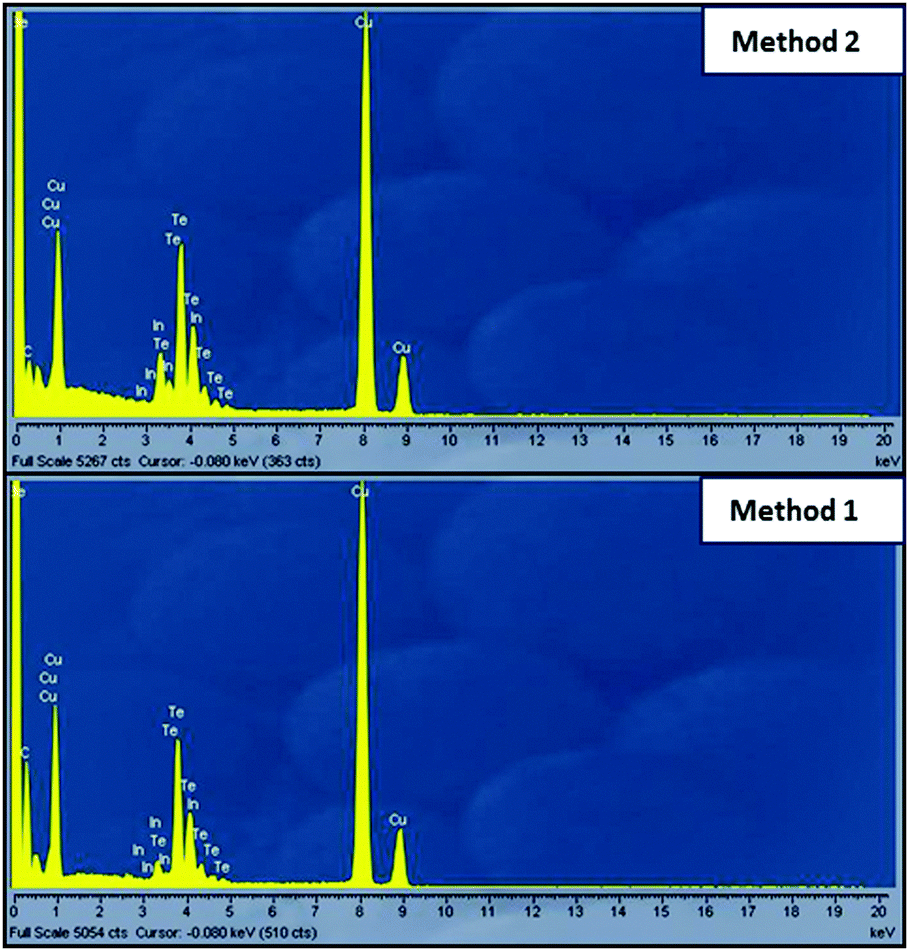 | ||
| Fig. 8 EDS spectra of TEM and HRTEM micrographs of CuInTe2 crystallites synthesized at 250 °C using method 2 and method 1. | ||
2.3 The proposed reaction path for the formation of phase pure CuInTe2
In recent years it has been shown that successful synthesis of colloidal nanostructures is ligand based.31 The appropriate ligand environment determines the overall thermodynamic and kinetics of the reaction via coordination to metal centers.31 Furthermore, it provides the colloidal stability and the structure direction by coordination to the surfaces of nanoparticles.31 These properties have helped postulate the crystallization mechanism of ternary and quaternary selenides and sulphides in the ligand system. Kar et al. investigated the formation pathway of CuInSe2 nanocrystals dissolved in oleylamine.32 Formation of the nanocrystals proceeded by initially forming binary CuSe and InSe which ultimately reacted forming CuInSe2.32 Carenco et al. investigated the role of the binary ligand system consisting of OLA and TOP in the synthesis of Ni nanoparticles.9 They delineated the roles of both OLA and TOP in the nucleation and growth of the nanoparticles. OLA was thought to be the reductant controlling the nucleation rate, while TOP provided a surface stabilization through coordination on the Ni(0) surface.9 In this work, we have a binary ligand system composed of OLA and TOP. OLA was selected as a solvent due to its basic capacity and strong chelating effect.33 The metal halides (InCl3 and CuCl) were dissolved in OLA thus activating Cl1−, In3+ and Cu1+ resulting from nucleophilic attack by OLA. Due to lower reduction potential of Te compared to S and Se, dissolution of Te in aliphatic solvents with considerable concentrations has not been reported.12 Specifically, E0(V) of X0 + 2e− ↔ X2− for X = S, Se, and Te are −0.48 V, −0.92 V, and −1.14 V, respectively.12 However, dissolution of the tellurium in phosphines could be achieved at high temperatures (∼350 °C) at relatively low concentrations.12 The reaction preceded by redox transfer thus oxidizing Te to Te2−. Based on the HSAB theory (Fig. 9), we hypothesized that because weakly polarized In3+ ions deemed to be hard acids, they will easily interact with Te2− ions as soft bases. The reaction will initially proceed by converting precursors to monomers, where In3+ and Te2− ions will be activated. As temperature increases, the monomer availability increases which facilitates the nucleation processes. This will permit the growth of In2Te3 nanocrystals which have a layered structure. During this time nucleation process will be controlled by OLA while the particle stabilization is provided by TOP. As temperature reaches 250 °C, we introduce the CuCl–OLA precursor into the reaction system. The Cu1+ ions will be activated. The Cu1+ ions will instantly react with In2Te3 through nucleophilic attack thus forming pure chalcopyrite CuInTe2 crystallites. Therefore, it is clear from the presented data the sequence in which the precursors are added is important and determines the reaction kinetics for the formation of pure CuInTe2 crystallites. | ||
| Fig. 9 Proposed reaction path for the formation of phase pure CuInTe2. | ||
3 Experimental
3.1 Materials and reagents
Copper(I) chloride (CuCl), Indium(III) chloride (InCl3), and elemental tellurium (Te) were all purchased from Sigma Aldrich. Trioctylphosphine (TOP), oleylamine (OLA), dichloromethane (CH2Cl2), chloroform (CHCl3), methanol (CH3OH) and ethanol (C2H6O) were all purchased from Sigma Aldrich and used without further purification.3.2 Synthesis of CuInTe2
Two methods were employed for the synthesis of CuInTe2. In method 1, 2.5 mmol of copper chloride and 2.5 mmol of indium chloride were added to 7 mL of OLA and heated to 120 °C under nitrogen. The mixture was then left under vacuum for 20 min before 2 mL of TOPTe (1 M) was injected. The solution was then further heated to 190 °C for 30 min. The temperature was then decreased to 60 °C. Methanol was added to the solution to flocculate the particles. The particles were then collected through centrifugation at 3000 rpm and washed with dichloromethane, ethanol, and methanol to remove the impurities. The temperature was varied from 190 °C–250 °C. In method 2, the sequence of addition of precursors was changed. Typically, 2.5 mmol of indium chloride was first added to 7 mL of OLA and heated to 120 °C under nitrogen. The mixture was then left under vacuum for 20 min. Thereafter, 2 mL of 1 M TOPTe was added. The solution was then further heated to 250 °C at which point 2.5 mmol of copper chloride dissolved in 2 mL of OLA was quickly injected. The temperature was maintained at 250 °C for 30 min. The particles were then collected and washed following the previous procedure.3.3 Characterization
XRD patterns of the powdered samples were recorded on a Bruker MeasSrv D2-205530 diffractometer using secondary graphite monochromated CoKα radiation (λ 1.78897 Å) at 30 kV/30 mA. Measurements were taken using the glancing angle of an incidence detector at an angle of 2°, for 2θ values over 20–90° in steps of 0.026° with a step time of 37 s and at a temperature of 25 °C. A Horiba Jobin-Yvon LabRAM HR Raman spectrometer equipped with a 514 nm argon laser was used for Raman spectral analysis. The transmission electron microscopy (TEM) was carried out on a FEI Technai T12 TEM microscope with an EDS detector operated at an acceleration voltage of 200 kV with a beam spot size of 20–100 nm in the TEM mode. UV-Vis-near-infrared spectroscopy of the powder samples was acquired on a Praying Mantis DRS Cary 500.4 Conclusions
Herein, we have shown that the colloidal method can be applied in the synthesis of ternary CuInTe2. High synthesis temperature was required for the formation of CuInTe2. At low temperatures 190 °C and 220 °C no formation of CuInTe2 was observed, only Te and Cu5Te3 phases were seen. The ideal synthesis temperature for CuInTe2 was 250 °C. At 250 °C, the sequence in which the precursor added was not only important for pure phase formation but it also aided in postulating the formation mechanism of CuInTe2. Highly agglomerated cubic structures were observed for pure CuInTe2, while mixed morphologies were obtained for impure crystallites. An optical band gap of 1.22 eV was obtained for pure CuInTe2 crystallites which is close to that of polycrystalline thin films. Therefore, it can be said that the colloidal method is an effective way of producing high quality nanocrystals that can be applicable in photovoltaics. However, further investigations into parameters such as the concentration, time and type of the capping agent are still needed in order to manipulate the optical and morphological properties of this material.Acknowledgements
The authors would like to thank the University of the Witwatersrand, School of Chemistry; the Microscopy and Microanalysis Unit (MMU) for TEM analysis and the X-Ray facility at Wits; Dr P. S. Shumbula from MINTEK for the HRTEM analysis and the National Research Foundation (NRF) for funding this project.Notes and references
- E. Witt and J. Kolny-Olesiak, Chem. – Eur. J., 2013, 19, 9746–9753 CrossRef CAS PubMed.
- S. Siebentritt and U. Rau, Wide-gap chalcopyrites, Springer, 2006 Search PubMed.
- M. Green, Solar cell efficiency tables (Version 41) Progress in Photovoltaics: Research and Applications, 2013, vol. 21, pp. 1–11 Search PubMed.
- L. L. Kazmerski, Renewable Sustainable Energy Rev., 1997, 1, 71–170 CrossRef CAS.
- I. V. Bodnar, V. S. Gurin, N. P. Solovei and A. P. Molochko, Semiconductors, 2007, 41, 939–945 CrossRef CAS.
- M. Boustani, K. El Assali, T. Bekkay and A. Khiara, Sol. Energy Mater. Sol. Cells, 1997, 45, 369–376 CrossRef CAS.
- S. Roy, B. Bhattacharjee, S. N. Kundu, S. Chaudhuri and A. K. Pal, Mater. Chem. Phys., 2003, 77, 365–376 CrossRef CAS.
- M. P. Kalenga, S. Govindraju, M. Airo, M. J. Moloto, L. M. Sikhwivhilu and N. Moloto, J. Nanosci. Nanotechnol., 2015, 15, 4480–4486 CrossRef CAS PubMed.
- S. Carenco, C. Boissiere, L. Nicole, C. Sanchez, P. Le Floch and N. Mézailles, Chem. Mater., 2010, 22, 1340–1349 CrossRef CAS.
- C. Kim, D. H. Kim, Y. S. Son, H. Kim, J. Y. Bae and Y. S. Han, Mater. Res. Bull., 2012, 47, 4054–4058 CrossRef CAS.
- M. A. Malik, P. O’Brien and N. Revaprasadu, Adv. Mater., 1999, 11, 1441–1444 CrossRef CAS.
- J. van Embden, A. S. Chesman and J. J. Jasieniak, Chem. Mater., 2015, 27, 2246–2285 CrossRef CAS.
- T. Omata, K. Nose and S. Otsuka-Yao-Matsuo, J. Appl. Phys., 2009, 105, 073106 CrossRef.
- R. G. Parr and R. G. Pearson, J. Am. Chem. Soc., 1983, 105, 7512–7516 CrossRef CAS.
- R. G. Pearson, J. Am. Chem. Soc., 1963, 85, 3533–3539 CrossRef CAS.
- M. Ananthan, B. C. Mohanty and S. Kasiviswanathan, Semicond. Sci. Technol., 2009, 24, 075019 CrossRef.
- F. Li and G. Yong-Quan, Chin. Phys. B, 2014, 23, 127801 CrossRef.
- K. Neyvasagam, V. Ramakrishnan, C. Sanjeevaraja and N. Soundararajan, Optoelectron. Adv. Mater., Rapid Commun., 2007, 1, 319–321 CAS.
- H. Tanino, H. Fujikake and H. Nakanishi, J. Appl. Phys., 1993, 74, 3821–3823 CrossRef CAS.
- C. Rincón, S. M. Wasim, G. Marín, E. Hernández, J. M. Delgado and J. Galibert, J. Appl. Phys., 2000, 88, 3439–3444 CrossRef.
- Q. Guo, S. J. Kim, M. Kar, W. N. Shafarman, R. W. Birkmire, E. A. Stach, R. Agrawal and H. W. Hillhouse, Nano Lett., 2008, 8, 2982–2987 CrossRef CAS PubMed.
- M. R. Ananthan and S. Kasiviswanathan, Sol. Energy Mater. Sol. Cells, 2009, 93, 188–192 CrossRef CAS.
- T. Mise and T. Nakada, Thin Solid Films, 2010, 518, 5604–5609 CrossRef CAS.
- A. Miller, A. MacKinnon and D. Weaire, in Solid State Physics, ed. F. S. Henry Ehrenreich and T. David, Academic Press, 1982, vol. 36, pp. 119–175 Search PubMed.
- H. Neumann, Helv. Phys. Acta, 1985, 58, 337–346 CAS.
- P. Prabukanthan and R. Dhanasekaran, Mater. Res. Bull., 2008, 43, 1996–2004 CrossRef CAS.
- C. Kim, D. H. Kim, Y. S. Son, H. Kim, J. Y. Bae and Y. S. Han, Mater. Res. Bull., 2012, 47, 4054–4058 CrossRef CAS.
- W. Hörig, H. Neumann, V. Savelev, J. Lagzdonis, B. Schumann and G. Kühn, Cryst. Res. Technol., 1989, 24, 823–827 CrossRef.
- D. Sridevi and K. V. Reddy, Thin Solid Films, 1986, 141, 157–164 CrossRef CAS.
- S. M. Wasim, A. LaCruz Vielma and C. Rincón, Solid State Commun., 1984, 51, 935–937 CrossRef CAS.
- N. Ortiz and S. E. Skrabalak, Langmuir, 2014, 30, 6649–6659 CrossRef CAS PubMed.
- M. Kar, R. Agrawal and H. W. Hillhouse, J. Am. Chem. Soc., 2011, 133, 17239–17247 CrossRef CAS PubMed.
- J. Zhou, G.-Q. Bian, Y. Zhang, Q.-Y. Zhu, C.-Y. Li and J. Dai, Inorg. Chem., 2007, 46, 6347–6352 CrossRef CAS PubMed.
Footnote |
| † Electronic supplementary information (ESI) available. See DOI: 10.1039/c6nj02108e |
| This journal is © The Royal Society of Chemistry and the Centre National de la Recherche Scientifique 2016 |