
 Open Access Article
 This Open Access Article is licensed under a
 Creative Commons Attribution 3.0 Unported Licence
Diffusion in nanoporous materials: fundamental principles, insights and challenges
Jörg
Kärger
*a and
Douglas M.
Ruthven
b
aFaculty of Physics and Earth Sciences, University of Leipzig, Linnéstraße 5, 04103 Leipzig, Germany. E-mail: kaerger@physik.uni-leipzig.de
bDepartment of Chemical and Biological Engineering, University of Maine, Orono, ME, USA
First published on 23rd February 2016
Abstract
Following a brief review of Fick's laws and the theory of diffusion in a homogeneous medium, we consider the application of the Fickian model to diffusion in nanoporous materials. If the pore system is statistically uniform the simple Fickian model is directly applicable. Inhomogeneities such as surface or internal barriers require some adjustments to the model but Fick's equations still provide a valid approach. Hierarchical pore systems present a more serious challenge. When there is rapid exchange between the different regions such systems conform to the simple Fickian model, with a diffusivity corresponding to the mean of the diffusivities in the different regions. In contrast, when the condition of rapid exchange is not fulfilled the simple Fickian model is not applicable and the situation becomes more complicated. Simple hierarchical pore structures such as the micropore/macropore system typically found in commercial adsorbents and catalysts can still be described by a dual resistance Fickian model but for more complex hierarchical pore structures Monte Carlo or MD simulations offer the only realistic approach. The measurement of self-diffusion by PFG NMR and by microimaging (notably by interference microscopy) is also reviewed and selected examples are presented to show the detailed information that can be extracted from such measurements, especially when accompanied by molecular simulations. Examples highlighting the relevance of a detailed knowledge of the various steps of mass transfer for a transport-optimized technological application of nanoporous materials, notably for molecular separations and mass conversions, are provided.
 Jörg Kärger | Jörg Kärger is Emeritus Professor of Physics at Leipzig University. His research activities, unabatedly continued after retirement, are dedicated to diffusion phenomena and novel techniques of their measurement and gave rise to the establishment of the Diffusion Fundamentals online journal and conference series. His book on Diffusion in Nanoporous Materials (Wiley-VCH, 2012), co-authored by Douglas Ruthven and Doros Theodorou, became standard in the field. His activities were recognized, among others, by the Donald W. Breck Award for zeolite research, the Max Planck Research Prize and election to the Saxon Academy of Sciences, just as by an entry in the Guinness book of records for conducting the largest orchestra of bicycle bells (during the Leipzig Physics Sunday Lectures). |
 Douglas M. Ruthven | Douglas Ruthven is Emeritus Professor of Chemical Engineering at the University of Maine. His research has focused on adsorption in porous materials and the application of adsorption in industrial separation processes. With generous support from the Humboldt Foundation he has collaborated extensively (over many years) with Professor Jörg Kärger and his students at the University of Leipzig. A revised edition of their 1992 book Diffusion in Zeolites was published by Wiley-VCH in 2012 under the title Diffusion in Nanoporous Materials. In addition to the Humboldt Fellowship he has received a number of honors and awards including the Max Planck Research Prize (jointly with Professor Kärger in 1993). He retired in 2011 but is still actively involved in a number of projects. |
1 Introduction
As a consequence of the thermal energy, atoms and molecules are subject to perpetual random motion. This motion leads to molecular migration (diffusion) which occurs, at very different rates, in all states of matter, and is a prerequisite for life as well as the key to many production technologies. This is particularly true for nanoporous materials and their many applications for upgrading of matter by adsorption, molecular separation and catalytic conversion. The overall process is easily understood to be a function of mass transfer so the output of value-added products can never be faster than allowed by the intrinsic rates of mass transfer. In many cases the practical and economic feasibility of a process depends on the values of the diffusivities, particularly on the differences in diffusivity between the components involved. In addition to its relevance for fundamental research, especially for a better understanding of system dynamics, mass transfer in nanoporous materials has thus acquired considerable technological importance.The role of mass transfer in the technological exploitation of nanoporous materials was recognized from the very beginning of their application to matter upgrading with the pioneering studies by Jüttner,1 Damköhler2 and Thiele.3 It was, however, only during the past few decades that guest diffusion in nanoporous host materials became accessible to study by direct experimental observation. Direct measurement of diffusion over length scales typically of micro-meters was enabled by the development of several microscopic measuring techniques which allow transient concentration profiles or molecular diffusion paths to be followed at this scale. Under properly selected conditions (the time scale of the measurement) the vast majority of the molecules under study will remain within the material under study, without being subjected to any disturbing influence from the boundaries of the individual crystals/particles or their surroundings. These new measurement options have contributed greatly to the recent paradigm shift in our understanding of mass transfer in nanoporous materials.4,5
Our contribution starts, in Section 2, with a review of the conditions under which mass transfer can be adequately described by Fick's laws of diffusion. Under such conditions, all the information on mass transfer that is relevant for the overall process is contained in a coefficient of diffusion (or “diffusivity”), a well-defined quantity defined in accordance with Fick's first law. A detailed description of the limitations of such a (comparatively simple) approach follows in Section 3. It is shown that more complex approaches are needed for some systems such as those with additional transport barriers or for hierarchical pore structures. Section 4 provides an introduction to the options and pitfalls of experimental measurements while Section 5 provides some examples showing the advantage to be gained from the combination of experimental measurements with theoretical modeling. Section 6 highlights two representative examples illustrating the link between fundamental research and practical applications. The concluding perspective summarizes the main insights achieved from past studies of nanoporous host–guest systems and reflects on some of the challenges for the future.
2. Mass transfer following Fick's laws
2.1 Theory of Fickian diffusion
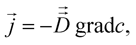
In the presence of a gradient of molecular concentration, a molecular random walk may be easily understood to give rise to a flux in the direction of decreasing concentration: there are, obviously, more molecules moving from the region of high concentration towards lower concentration than in the reverse direction. Continuing this consideration and neglecting any effects of non-linearity, the number of molecules moving towards the lower concentration is seen to increase in direct proportion with the concentration gradient. This and nothing more than this is expressed by Fick's 1st law of diffusion: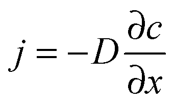 | (1) |
| ∂c/∂t = −∂j/∂x | (2) |
 | (3) |
 | (4) |
Eqn (4) is obviously also applicable to labelled molecules within an entity of unlabelled molecules of identical properties, for constant overall concentration of total (labelled plus unlabelled) molecules, since the diffusivity of the labelled (and unlabelled) molecules is a function of the overall concentration and not of how many molecules have been labelled. Typically isotopes of the species under consideration are used as labelled molecules (“tracers”). The diffusivity under such conditions is referred to as the self- or tracer diffusivity while, for distinction, the diffusivities observed with an overall concentration gradient (Dt) are referred to as transport diffusivities (or, completely equivalently, collective, chemical or center-of-mass diffusivities).
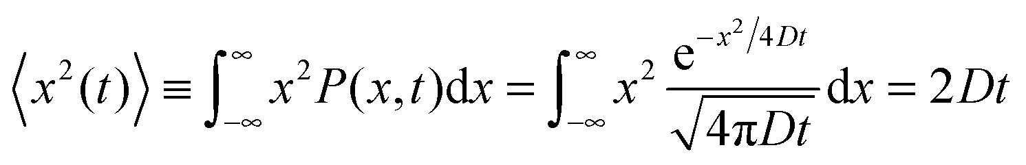
Let us consider the evolution of molecular concentration in the particular case when, at the beginning of the experiment (t = 0), all molecules are located at essentially one position (x = 0). This is exactly the situation specified in diffusion measurement by NMR (see Section 4.3) with “labelled” molecules. Then, as a solution of eqn (4), we have:
 | (5) |
 | (6) |
 | (7) |
As a primary prerequisite for their validity, Fick's laws have to deal with meaningful quantities. This means that fluxes and concentrations must be defined with respect to unit areas and unit volumes which are sufficiently large in comparison with the individual cages in pore space.6 Only then may the fluxes and concentrations be expected to be homogeneous functions in space and time. The individual space elements are quite complex systems. In a statistical sense, however, they are uniform throughout the sample.
The complexity of the space elements leads to widely different molecular mobilities, e.g., on the pore surfaces and within the pore space, and, possibly, even in molecular traps. In a first-order approach, these different states of mobility may be quantitated by their relative populations pi and diffusivities Di. If the molecular mean life times in each of these states are short in comparison with the mean exchange time between different unit volumes, by simple random walk arguments overall mass transfer7,8 is easily seen to follow Fick's laws, with the diffusivity corresponding to the weighted mean of the diffusivities in the various states
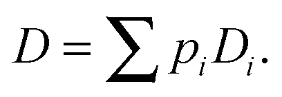 | (8) |
By increasing the unit volume without limit, the mean exchange time between different unit volumes may clearly be arbitrarily increased so that, by choosing large enough unit volumes – at least theoretically – all exchange times between different states of mobility may eventually be exceeded. In reality, however, an upper limit is imposed by the size of the system since, as another prerequisite for the validity of eqn (1), (3) and (4), the unit volume has to be much smaller than that.
Eqn (8) includes, as a special case, the diffusion-immobilization model.13 Here, the molecules are assumed to be either trapped (immobilized) or mobile, so that eqn (8) simplifies to
| D = pmobileDmobile | (9) |
Fick's laws in the form of eqn (1), (3) and (4) remain applicable also to nanoporous materials of anisotropic pore structure if mass transfer in one of the principal directions of the diffusion tensor is considered and these directions coincide with the crystallographic axes (e.g. for orthorhombic symmetry). Quite generally, Fick's 1st law must now be written in the form25
 | (10) |
 .
.
Diffusive fluxes under multicomponent adsorption must, in general, be assumed to be affected by the concentration gradients of all components leading to a generalization of Fick's first law in the form
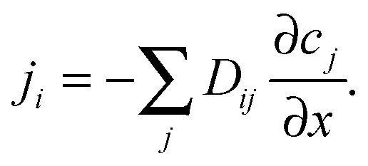 | (11) |
By introducing eqn (11), jointly with an appropriately chosen reaction term, into the continuity equation, eqn (2), the influences of both diffusion and reaction on the spatial-temporal dependence of the concentration ci of the involved components may be described by:
 | (12) |
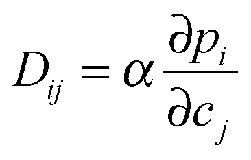
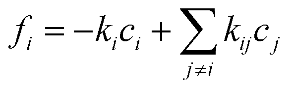 , yielding the well-known expression for diffusion with first order reaction. For simplicity, the elements of the diffusion tensor are generally assumed to be independent of concentration (as implied already by eqn (4)). We shall return to this in Section 4.2. Where, with Dij = Dδij and fi(c1…ci…cn) = −kci, eqn (12) is shown to nicely reproduce the evolution of the concentration profiles during hydrogenation of benzene to cyclohexane as recorded by IR microimaging.
In summary, provided that diffusion is the dominant mechanism and molecular exchange between different regions is sufficiently rapid, even for systems that include many different regimes of molecular propagation, mass transfer in nanoporous materials is fully described by Fick's laws (eqn (1), (3) and (4)) and their extensions to anisotropic materials and multicomponent adsorption (eqn (10) and (11)). In such cases, viaeqn (8), overall diffusivities can often be referred to more fundamental parameters such as the diffusivities in the different fluid phases, the tortuosity of the pore spaces and the relative occupation numbers. As a consequence, it became popular to refer to these quantities as “effective” diffusivities, even though they fit perfectly with Fick's laws and are therefore genuine diffusivities according to the formal definition. Referring to a diffusivity as an “effective diffusivity”, however, carries the risk that this quantity may be understood as being something other than a true diffusivity. Even more confusing is the use of the term “effective diffusivity” to refer to transport parameters which do not conform to Fick's laws and which are therefore not diffusivities in any strict sense. Furthermore, transport in small pore systems in which the pore diameter is only slightly larger than the diameter of the guest molecule conforms to Fick's laws but the diffusivities are not directly related to fluid (or solid) phase diffusivities and therefore cannot properly be described as “effective diffusivities”. The logical solution is to refer to diffusion parameters derived from Fick's laws as simply “diffusivities”. Such a convention would, as a matter of course, not exclude further specifications within the given context, such as reference to the diffusivities of liquids as a fundamental quantity of their properties.
2.2 Concentration dependence of diffusivity
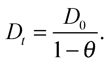
Despite some debate in the literature in the early 1970s (see, e.g., ref. 26), the fundamental role of the gradient of chemical potential for diffusive transport is beyond any doubt. This interrelation follows directly from irreversible thermodynamics (see, e.g., ref. 27 or chapter 3 in ref. 5) and suggests that, in many cases, considering the gradient of chemical potential rather than the concentration gradient as the driving force for diffusion provides a simpler representation. In this way, the Fickian transport diffusivity (Dt) defined by eqn (1) results as the product of an intrinsic mobility (D0), also referred to as the “corrected diffusivity”, and a factor (dln![[thin space (1/6-em)]](https://www.rsc.org/images/entities/char_2009.gif) p/dlnc) which takes account of the non-linearity of the relationship between activity and concentration, as defined by the equilibrium isotherm:
p/dlnc) which takes account of the non-linearity of the relationship between activity and concentration, as defined by the equilibrium isotherm: | (13) |
 | (14) |
 | (15) |
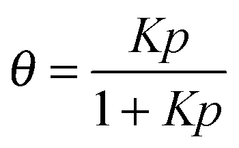
In principle D0 is also a function of loading, so quite complex patterns of behavior are possible. They appear in the various types of concentration dependences of the self-diffusivities28,29 which may vary over as much as two orders of magnitude. However, it has been found experimentally that, for small pore systems, especially when the pore system consists of cages interconnected through small (typically 8-ring) windows, the concentration dependence of Dt is generally stronger than that of D0.
Transition state theory provides a simple explanation for this pattern of behavior. For such systems the passage of molecules through the windows is an “infrequent event” (see, e.g., chapter 9 in ref. 5) and the “corrected” and self-diffusivities (D0 and D) are found to be essentially the same, with the ratio of transport to self-diffusivity given by the thermodynamic correction factor 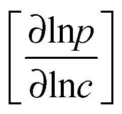 .30 The advent of IRM offered the opportunity to determine, with the same device, both transport diffusivities (by following molecular uptake or release) and self-diffusivities (by following tracer exchange) thus ensuring that the respective data sets are indeed directly comparable with each other. Results of such measurements are discussed in Section 5.
2.3 Maxwell–Stefan formulation
Although eqn (11) provides a formally correct expression for transport in a multi-component adsorbed phase it is of limited practical value as long as it is not associated with clear instructions how the elements Dij in the diffusion matrix can be determined. With the experimental data of two-component uptake by DDR-type zeolites and their prediction from two-component adsorption, Section 5.2 provides such an example. As a common source of this access, one may refer to the mechanistic theory of diffusive transport developed only a few years after Fick's seminal paper31 (independently) by Maxwell32 and Stefan33 which implicitly recognized the chemical potential gradient as the driving force. In the 1990s the application of the Maxwell–Stefan model to transport in nanoporous materials was studied in detail by Krishna and his co-workers – see for example ref. 34. A short summary and review of this work has been presented in Chapter 3 of our book.5The basic expression for the Stefan–Maxwell equations applied to diffusion in a nanoporous structure is:
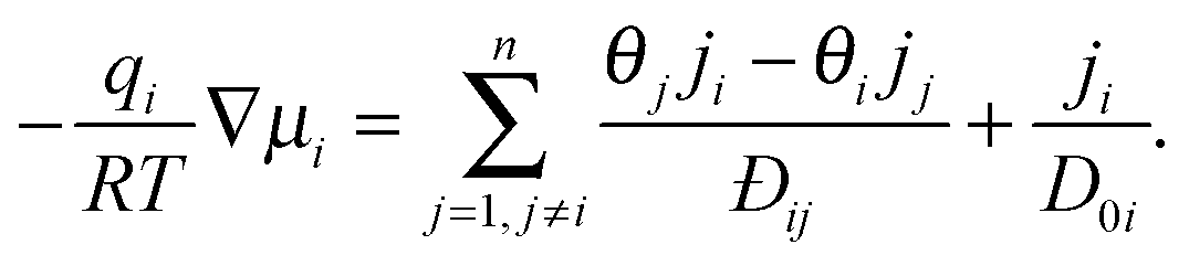 | (16) |
If we consider tracer diffusion according to the Maxwell–Stefan model we obtain a useful general relationship between the self- and corrected diffusivities:37
| 1/D = 1/D0 + Θ/Đii | (17) |
3. More complex pore structures
In our discussions so far, pore space has been considered to be homogeneous, with either strict regularity as in a crystalline or other ordered structure (at least in a statistical sense). Moreover, mass transfer was considered to be exclusively controlled by diffusion in accordance with Fick's laws (eqn (1), (3) and (4)) or their extensions (eqn (10)–(12)). We now relax this second assumption. In a first subsection we take account of the fact that, in addition to the diffusional resistance of the genuine pore system, mass transfer may also be controlled by “barriers” which may be either distributed within the bulk phase of the nanoporous particles or on their external surface. We then consider a couple of systems which one may have in mind as models if the conditions leading to the fast-exchange relation, eqn (8) are not fulfilled.3.1 Transport barriers
Transport resistances (“barriers”) acting in addition to the diffusional resistance of the pore space are generally introduced in terms of a (surface or barrier) permeability α by the relation13| j = αΔc | (18) |
In the simple case of equally spaced transport resistances (spacing l assumed small in comparison with the particle length L) and of equal permeability α, perpendicular to the x direction, eqn (1), (3) and (4) are easily shown to hold also in this case, with a diffusivity given by the reciprocal addition rule:
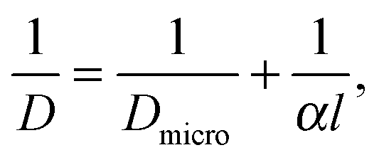 | (19) |
It is important to note that, with the definition of the surface permeability α by eqn (18), exactly this equation, in combination with Fick's 1st law, eqn (1), assumes the function of the boundary condition for solving Fick's 2nd law, eqn (3) or (4), in place of the condition cboundary = cequilibrium which applies for complete diffusion control.
In analogy with the considerations about the unit volumes and unit areas required for a meaningful definition of Fick's 1st and 2nd laws, the surface barrier must also be – at least in a statistical sense – homogeneous over the external surface of the particle under consideration. The thickness of the surface layer must be sufficiently small in comparison with the extension L of the particle, but may notably exceed the individual pore size. It follows directly from eqn (18) that the (intraparticle) guest concentration “close” to the boundary may assume values that differ significantly from the equilibrium concentration (to which it would be equal in the absence of surface resistance). We shall return to this point by looking at the evolution of intracrystalline concentration profiles in Section 4.2, where the shape of the concentration profiles is shown to depend dramatically on the relationship between surface permeation and intracrystalline diffusion.
With eqn (18), the surface permeability is seen to operate with the same magnitude in either direction, i.e. for molecular uptake and release. Within the framework of Fick's laws and with the boundary conditions as classified in the literature for this type of equation13,38 the surface resistance is thus seen to operate completely symmetrically in either direction. This finding is in complete agreement with the requirement of equilibrium which would be disturbed by any imbalance between uptake and release – to which we shall refer in greater detail in Section 4.2 when comparing transient uptake and release as a function of the pressure steps. However, this symmetry applies only for linear (constant diffusivity) systems. The literature is replete with both experimental and modeling studies claiming asymmetry between adsorption and desorption – see for example ref. 39 and 40. It remains to be seen whether such observations truly represent the micro-dynamics or whether they can be accounted for by non-linearities.
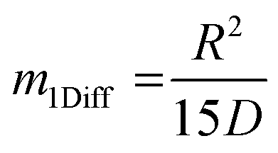
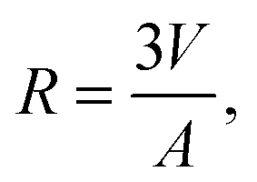
Assessment of the relative importance of intracrystalline diffusion or surface barriers on overall mass transfer may conveniently be based on the respective values of the first statistical moment,5,41,42 defined by the relation
 | (20) |
 , the time constant τ appearing in the exponent is immediately seen to coincide with the first statistical moment m1. With the respective time dependences of m(t), the time constants of uptake and release may thus be found to be5,42
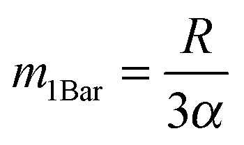 | (21) |
 | (22) |
 | (23) |
For the two transport resistances acting in parallel, the overall time constant of uptake and release simply results as the sum of the two terms.5,42 As a consequence of the different dependencies on the particle size, the relative importance of the diffusional resistance (∝R2) in comparison with the surface resistance (∝R) is seen to increase with increasing particle size, while – vice versa – the importance of surface resistance increases with decreasing particle size. A recent example of this interdependence has been provided by Teixeira et al.40 who used the ZLC technique to study the kinetics of sorption of cyclohexane in zeolite MFI.
3.2 Finite exchange rates: diffusion in hierarchical pore systems
Overall mass transfer in heterogenous systems has been found to be well described by Fick's laws (with diffusivities as predicted by eqn (8) and (9)) provided that the mean exchange times between different states of mobility are sufficiently small in comparison with both the overall time scale of the experiment and the mean life time of the molecules in the individual unit volumes implicit in the definition of the concentrations. Deviations from this requirement may give rise to quite different patterns of overall mass transfer, depending on the given situation. Examples include the diffusion-immobilization (or diffusion-reaction) model which allows for an unrestricted variation of the immobilization (reaction) time.13 Isotopic cation exchange in zeolite X43 and the uptake of pyronin B in MOF-544 have been observed to nicely follow such patterns. In both cases, the “guests” under consideration undergo intimate interactions with the host scaffold.Most commercial catalysts and adsorbents consist of small microporous micro-particles often aggregated, for example, with the aid of a clay binder to form a macroporous pellet (typically of 0.5–3 mm diameter for fixed beds). Such materials have a relatively simple and well defined hierarchical pore structure in which the transport behavior can be modeled by representing the system as two coupled diffusional resistances.45–47 It would be relatively straightforward to extend such models to incorporate a transport barrier at the surface of the micro-particles but, as far as we know, this has not actually been done. In more complex hierarchical pore systems involving structured networks of “transport” pores introduced into a micro/mesoporous bulk phase, designed to accelerate the contact of the molecules in the surrounding fluid with the pore space20,48–53 modeling transport beyond the regime of rapid exchange is a more challenging task.
The scheme shown in Fig. 1 provides an introduction to the complexity of the transport phenomena occurring under such conditions. This scheme has been used in ref. 12 to explore the influences of the different parameters inherent to such a system on overall mass transfer rates. A purely microporous body (top right) is assumed to be percolated by a network of mutually intersecting equidistant channels (outermost right), with a cross section through a plane with intersecting channels shown top left. For visual convenience only 5 × 5 × 5 channels are shown, rather than the actual 18 × 18 × 18 ones considered in the simulations (Fig. 2). The simulations in ref. 12 were performed using the model illustrated in Fig. 1, i.e. by considering a network of equidistant points of separation l (bottom left), but with notably higher occupation probability and lower jump rates (1/τ) in the range of micropores (shaded part) than in the mesopores – corresponding with the potential landscape shown bottom right.
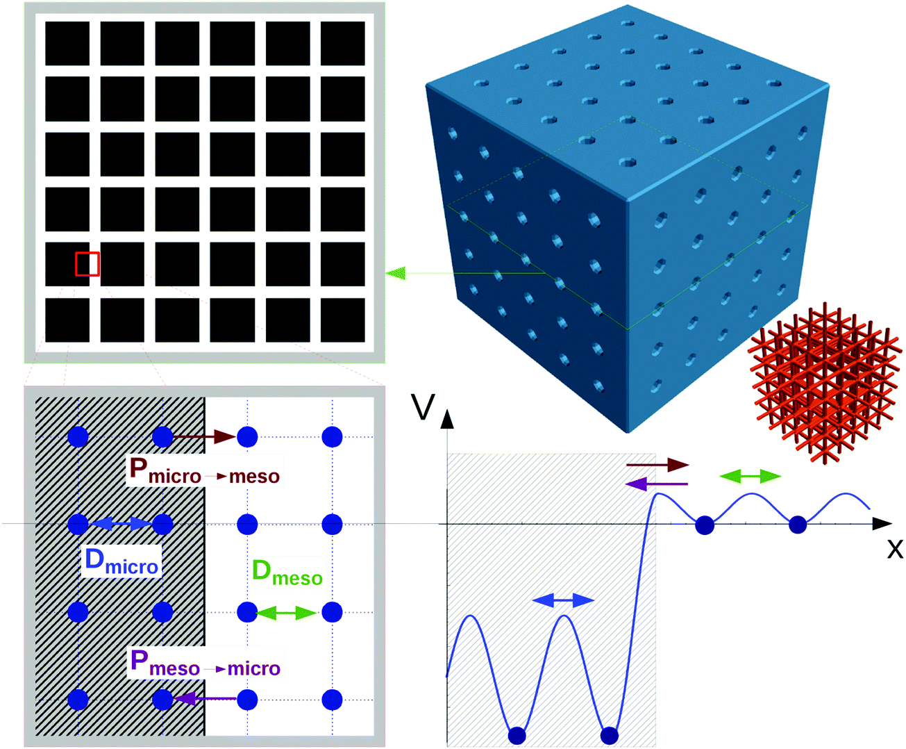 | ||
| Fig. 1 Scheme for simulating molecular uptake by a hierarchically organized, regular pore network. A continuous microporous phase (top right) is traversed by a network of mesoporous channels (outermost right). Corresponding with the potential landscape on bottom right, the space of micropores (shaded area on bottom left) is distinguished from the mesopores by a higher population density and reduced jump rates. For visual convenience, only 5 channels in parallel (rather than the actually considered 18 ones) are considered. Reprinted with permission from ref. 12. Copyright©2015 John Wiley and Sons. | ||
 | ||
| Fig. 2 Density evolution of selected simulation runs with the network shown in Fig. 1 for the limiting cases of fast exchange (top) and slow exchange (bottom). The density profiles are obtained by summing over a cylinder-shaped cut of radius R = 15 lattice nodes through the crystal center and refer to instants of time with overall uptake equal to 20% (center) and 70% (right) of its final value. Reprinted with permission from ref. 12. Copyright©2015 John Wiley and Sons. | ||
With the relation
 | (24) |
| Dmeso ≫ Dmicro. | (25) |
| pmeso ≪ pmicro. | (26) |
 | (27) |
 | (28) |
Eqn (28) provides an estimate of the time constant in the opposite limiting case of slow exchange. In this case, mass transfer through the mesopores is sufficiently fast so that the boundary condition for molecular uptake by the micropores is fulfilled, essentially instantaneously, all over the internal surface of the mesopores. Correspondingly, the parameter Rmicro in eqn (28) appears as a measure of the extension of the purely microporous space between two “adjacent” mesopores. Using again eqn (23) as a first-order estimate, one may note
 | (29) |
Fig. 2 illustrates the dramatic differences in the uptake patterns which may be observed with such systems. Both representations show the density of the guest molecules during uptake at two instants of time, characterized by the condition that the average guest concentration has attained 20% (center) and 70% (right) of the final (equilibrium) state. The difference between the two cases considered (fast exchange with τmicro/τcryst = 0.04 top; slow exchange with τmicro/τcryst = 50.24 bottom) appears particularly distinctive with the representations on the right. They show the respective density profiles evaluated from a cylinder-shaped cut with a radius of 15 lattice nodes through the particle center. Following the features predicted already in Section 2 from the simple Fickian model, molecular uptake under fast-exchange conditions (top) is seen to proceed with the propagation of a diffusion front from the external particle surface into its interior. In the bottom figure however, under slow-exchange conditions, uptake into the micropores is seen to occur essentially simultaneously all over the particle, starting from the surface of the mesopore space.
With variation of the guest molecule under consideration, for the same host systems, micro- and mesopore diffusivities and the respective populations may assume quite different values. Consequently, the characteristic time constants defined by eqn (27) and (28), and their ratio may also assume quite different values – leading to different patterns of overall mass transfer behavior. These relations would be additionally complicated by the influence of surface barriers – both on the external surface and on the interface between the meso- and micropores. Following the considerations at the end of the preceding Section 3.1, the (desired) reduction of Rmicro in comparison with Rcryst tends to enhance the relevance of the latter type of surface barriers. The increased complexity of the influences possibly affecting overall mass transfer in hierarchical pore systems increases the challenges of their experimental measurement – which are in any case severe enough for even such apparently simple systems as genuine microporous materials. We return to this issue in Section 4.
The complexity of the phenomena contributing to mass transfer in hierarchical pore systems complicates their theoretical treatment beyond the simple framework provided by Fick's laws. In such cases, effective medium approaches have proved to be a useful alternative towards an analytical description of mass transfer.54 More direct correlations between system properties and mass transfer may be established via dynamic Monte Carlo simulations (see, e.g.ref. 12 and Fig. 1 and 2) and molecular dynamics simulations.21,55 allowing, e.g., the straightforward inclusion of the effect of strong adsorption sites on overall diffusion.56 Challenges for future research include developing reliable predictions for the conditions of mass transfer in nanoporous particles under technical use. The development of strategies towards structure optimization for mitigating their deactivation and transport inhibition becomes, in this context, an important task for future material-related research.52,57
4. Diffusion measurement: options and pitfalls
It has been shown in Section 2 that diffusivities may be defined in three different but equivalent ways: via Fick's 1st law (eqn (1), (10) and (11)) as a factor of proportionality between diffusive fluxes and concentration gradients; viaeqn (3) and (4) as the factor proportionality between temporal and second-order spatial derivatives of the concentration; or, through the Einstein equation (eqn (7)), from the mean square displacement in a known interval of time. Each of these definitions leads to alternative approaches for the experimental measurement of diffusivities. The advantages and disadvantages of the various techniques have been discussed in detail in our book;5 we therefore present here only a few brief comments with emphasis on the more recent developments.4.1 Macroscopic measurements
The earliest measurements of diffusivities in nanoporous materials were made by following the rates of adsorption (or desorption) under well controlled initial and boundary conditions (typically a step change in pressure or partial pressure at time zero). For slow systems this approach yields reliable data from which accurate diffusivity values can be extracted. However, when the uptake rate is high it may be strongly affected or even controlled by extraneous processes such as heat transfer or extra-particle mass transfer. Such intrusions are often not obvious, so careful experimentation (for example varying both particle size and sample configuration)58 is necessary to eliminate these effects.More recently a wide range of more sophisticated methods such as frequency response, chromatographic methods and the zero length column (ZLC) technique have been introduced in order to avoid such problems. In recent years the ZLC technique (see ref. 59 and pp. 483–500 in ref. 5) has become widely accepted as the method of choice for rapid approximate characterization of the transport properties of nanoporous adsorbents. It offers the advantage that it yields values for the Henry constant, the limiting diffusivity and the surface resistance (if significant) from a single set of measurements carried out over a range of flow rates. It is also easily automated for routine characterization.60 However, for fundamental studies of diffusion and transport mechanisms, detailed information can be derived more easily from microscopic measurements, either from measurements of the transient concentration profiles or from measuring the mean square molecular displacement over a known time interval.
4.2 Microimaging
Among the various methods of recording guest molecules in nanoporous materials,61–63 the techniques of interference microscopy64 (IFM) and IR microscopy65,66 (IRM) have proved to be particularly well suited for following the evolution of guest concentrations during transient uptake and release.67,68 Their principles of operation make these two techniques complementary to each other. IRM is based on the analysis of the IR absorption spectra recorded by the individual elements of a “focal plane array” detector allowing spatial resolutions down to 2.7 μm × 2.7 μm in ideal cases but, more realistically, in the range of 5 to 10 μm. Depending on the number of characteristic bands accessible in these spectra, various components may be recorded separately from each other. Such a distinction is not provided by IFM which, however, is able to attain much better spatial resolution (≈0.5 μm). With reference to Section 2, the concentrations thus recorded correspond with volume elements with edge lengths of (or above) 2.7 μm if recorded by IRM and of (or above) 0.5 μm with IFM. Thus, for a meaningful, spatially resolved measurement of intracrystalline mass transfer the extension of the particles under study should be a least of the order of a few tens of μm for IRM and of at least 10 μm for IFM. With the presently available devices, imaging experiments may be performed from room temperature up to about 100 °C.Since IFM is based on measuring the optical density of the crystal under study, in addition to guest concentration it is also able to detect variations in the lattice structure. These variations may be recorded as a function of space and time as in a recent study of benzene adsorption on silicalite-1.67 The information thus provided for the study of framework flexibility has not hitherto been accessible by direct measurement.69,70
Both IFM and IRM record the integral  in the observation direction rather than the local concentration c(x,y,z) itself. Often, however, and notably with host systems traversed by channel pores in only one or two dimensions, concentration becomes a function of only one or two dimensions so that the concentration integral degenerates into the simple product L × c(x,y). In either case, information is provided in relative units. Absolute numbers have to be determined by comparison with conventional adsorption isotherms. More information about the experimental aspects may be found in the relevant literature, including ref. 66, 67, 71–73.
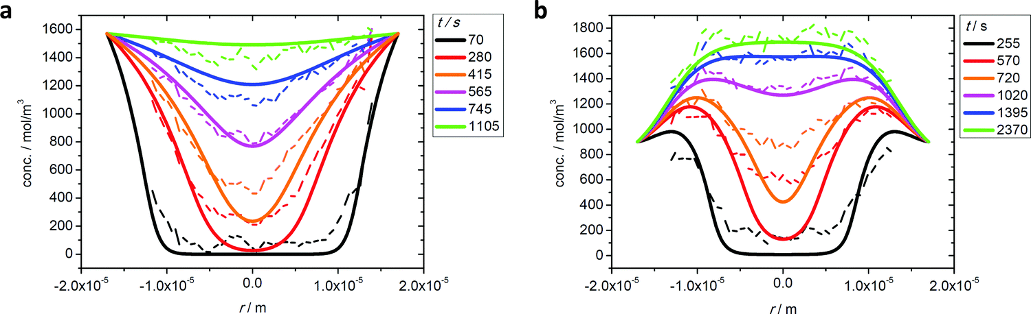
Fig. 3 exemplifies the potential of IFM showing the concentration profiles thus recorded during molecular uptake (left) and release (right) along the 8-ring channels of zeolite ferrierite initiated by pressure steps between 5 and 10 mbar (top) and 0 and 40 mbar (middle) in the surrounding atmosphere of methanol.74,75 The unified presentations of uptake and release in Fig. 3(e) (bottom left) for the small pressure step and in Fig. 3(f) (bottom right) for the large pressure step highlight a most significant difference on comparing uptake and release. While the respective curves for uptake and release are essentially reversible for the small pressure step, they are seen to differ dramatically from each other for the large pressure step. With reference to eqn (3) and (4), this difference may easily be attributed to the change in the character of the differential equation. For the small pressure step the diffusivity may be assumed to remain constant, with Fick's law becoming, in the form of eqn (4), a linear, homogeneous equation. In this case, the sum of two solutions (e.g. those of uptake and release over the same pressure step) is once again a solution (in the given case constancy, corresponding with the overall behavior during tracer exchange). This is not the case for concentration dependent diffusivities. In the common case of transport diffusivities increasing with increasing loading, uptake is found to occur at a notably faster rate than desorption. The presentations of Fig. 3(e) and (f) nicely illustrate that desorption over the large pressure step remains essentially unchanged, being controlled by the magnitude of the diffusivity in the range of small concentrations. Exactly this property has been exploited already many years ago for the determination of the limiting diffusivities at zero loading from macroscopic sorption curves.76
 | ||
| Fig. 3 Relative molecular uptake and release of methanol in ferrierite-type zeolites along the 8-ring channels: Comparison of experimentally determined and calculated profiles for pressure steps (a) 5 to 10 mbar, (b) 10 to 5 mbar, (c) 0 to 40 mbar and (d) 40 to 0 mbar. The points refer to experimental measurements, the lines are numerical solutions of Fick's 2nd law with concentration dependent transport diffusivities and surface permeabilities. By plotting the concentrations from top to bottom for adsorption, in plots (e) and (f) profiles after selected times during ad- and desorption are shown in a unified representation. Here, for simplicity, only one half of the profiles (starting with x = 23.8 μm in the crystal centre) is shown. Adapted with permission from ref. 74 and 75. Copyright©2006 American Chemical Society and Copyright©2009 John Wiley and Sons. | ||
During uptake and release, the boundary concentrations of the profiles shown in Fig. 3 notably deviate from their equilibrium values. With eqn (18), differences between actual and equilibrium loading indicate the existence of surface barriers, resulting in finite values of the surface permeability. The result of a systematic study of surface permeabilities for propene in AlPO–LTA is shown in Fig. 4. We note that the permeabilities determined during ad- and desorption agree with each other as expected. There is, moreover, a remarkable similarity between the concentration dependence of the intracrystalline diffusivities and that of the surface permeabilities. The diffusivity-to-permeability ratio for a given crystal is found to remain constant although, with varying concentration, both quantities vary over close to two orders of magnitude. A similarly remarkable constancy of the diffusivity-to-permeability ratio was also found for light n-alkanes in Zn(tbip).77 As a consequence, both intracrystalline diffusion and surface permeation must be controlled, at least for these systems, by identical limiting steps. Exactly this would be expected if the surface barrier is caused by an essentially impermeable layer with widely dispersed holes.78 For a three-dimensional pore lattice, in this case by effective medium theory79 the surface permeability could be estimated as
 | (30) |
 | ||
| Fig. 4 Transport diffusivities Dt (squares) and surface permeabilities α (triangles) of propylene in AlPO–LTA at 295 K, calculated from the transient concentration profiles recorded by IFM during molecular uptake following stepwise pressure change. Reprinted with permission from ref. 82. Copyright©2012 American Chemical Society. | ||
The possibility that intracrystalline barriers might be of a similar nature straightforwardly explains why, for many different systems, the diffusivities deduced from “macroscopic” (e.g. uptake) and “microscopic” measurement (with displacements shorter than the barrier spacing) were found to follow similar trends (with, e.g., similar activation energies), though often differing significantly in their absolute values:80,81 inserting α from eqn (30) into eqn (19), the overall diffusivity as observable by “macroscopic” measurement is immediately seen to be proportional to the “microscopic” diffusivity, reduced by a factor determined by the size and distance between the “holes” and the barrier spacing.
Fig. 5 illustrates how the potential of IRM may be exploited for the in situ observation of the evolution of the concentration of the various components involved in a chemical reaction.83 By simultaneously recording conversion and reaction, IRM offers unprecedented potential for the purposeful fabrication of transport-optimized catalysts.84 With the given temperature range from room temperature up to about 100 °C, hydrogenation of benzene to cyclohexane catalyzed by finely dispersed nickel proved to be a most convenient test reaction. The use of nanoporous glass as a carrier material85 was suggested by its repeated successful application as a standard host material in diffusion studies, including the experimental proof of the ergodic theorem86 for normal diffusion87 and of the compatibility between micro- and macroscopic measurements.88 The glass is applied as a thin platelet, with top and bottom faces sealed with a silica layer.89 As a consequence, uptake and release took place on only the platelet edges. The profiles are recorded perpendicular to these edges. The complete set of profiles for the measurement at 75 °C is shown in Fig. 6.
 | ||
| Fig. 5 Monitoring reactant and product concentration profiles during the conversion of benzene (red) into cyclohexane (blue) in nanoporous materials by microimaging, with the arrows in green indicating the spatial extensions relevant for our experiments. Reprinted with permission from ref. 83. Copyright©2015 John Wiley and Sons. | ||
 | ||
| Fig. 6 Transient concentration profiles during hydrogenation of benzene to cyclohexane at 75 °C. The experiments are started by contacting an initially empty catalyst with a benzene–hydrogen atmosphere (pbenzene = 27 mbar; phydrogen = 977 mbar). Data points represent the experimental results obtained by IR microimaging (circles: benzene (A), diamonds: cyclohexane (B), reflecting meaningful concentrations for x ≥ 50 μm). The solid (benzene (A)) and dashed (cyclohexane (B)) lines are results of the analytical solution of eqn (12) with the relevant initial and boundary conditions. Reprinted with permission from ref. 83. Copyright©2015 John Wiley and Sons. | ||
As a remarkable feature of the results for the given temperature, benzene is seen to enter the catalyst carrier with its diffusion front propagating already over a substantial distance before a considerable part of it is converted into cyclohexane. The benzene profiles are thus seen to approach already their final shape while there is still an appreciable increase in cyclohexane concentration. The final shape of the profiles is determined by the requirement that the rates of benzene uptake, cyclohexane release and conversion from benzene to cyclohexane are consistent. With the experimental data, under the considered conditions the system is seen to have eventually attained this stage after about one hour.
The full lines show the best fit of the solution of eqn (12) to the experimental data. The agreement is seen to be already quite satisfactory, irrespective of the simplifying assumption that the diffusivities of both components coincide and that, moreover, any concentration dependence has been neglected.
Most importantly, the area under the finally attained concentration profile of benzene, the reactant profile, is seen to represent the effectiveness factor of the reaction under study. Since the pioneering papers by Jüttner,1 Thiele3 and Weisz,90 in a century-old history this key number for the efficiency of catalytic reactions has thus finally become accessible by direct measurement. This type of information would become even more directly accessible by use of a single-element detector for signal recording since, in that case, it is the integral over the different guest concentrations that is recorded. Moreover, by abandoning the option of spatial resolution, the experimental requirements are substantially relaxed quite in general. IR microimaging based on the use of single-element detectors may thus turn out to provide the best potential for becoming a routine technique for future research in heterogeneous catalysis.
Fig. 6 may also be used to illustrate some of the presently existing limitations in microimaging. With the given devices, e.g., time resolution in IRM is limited to minutes – and to tens of seconds in IFM. In IRM, however, by the use of a single-element detector, measurements with time constants of the order of seconds have already become possible.91 Since, in the IR microscope used for these studies, light is focused into the focal plane under an angle of about 16° towards observation direction (rather than in observation direction, see e.g. ESI to ref. 72), spatial resolution deteriorates with increasing sample thickness. Close to particle boundaries, moreover, an increasing region becomes inaccessible by reliable observation. This is indicated in Fig. 6 by the data points in grey.
4.3 Pulsed field gradient NMR
Nuclear magnetic resonance (NMR) is based on the fact that nuclei generally possess both a magnetic moment and a moment of inertia. Under the influence of a magnetic field B, nuclei in their quasi-classical interpretation – as for a gyroscope under the influence of gravity – may thus be expected to perform a rotational (“precessional”) motion with an angular frequency| ω = γB | (31) |
In the pulsed field gradient (PFG) technique of NMR, a constant magnetic field B0 is superimposed, over two short time intervals δ of separation t, by an additional, inhomogeneous field Badd = gx, the so-called field gradients. Inserting B = B0 + Badd = B0 + gx into eqn (31) yields
| ω = γB0 + γgx. | (32) |
In PFG NMR one exploits the fact that a shift over a distance x (in the x direction) during the time interval t between the two sequential gradient pulses, leads to a difference in the angular frequencies during the two gradient pulses. With eqn (32) this difference is easily seen to be equal to γgx (where now x stands for the displacement rather than the location). Under equilibrium conditions, as usually considered in PFG NMR studies, molecular displacements must be zero on average. Particle shifts over a distance x thus give rise to a phase shift (relative to the mean direction of nuclear magnetization) which simply results as the product of the difference in the angular frequencies, γgx, and the time span δ during which the two field gradient pulses are applied. Just as in normal vector addition, such spins contribute to overall magnetization only with the cosine of the phase shift. Overall signal attenuation may therefore be expressed in the form
 | (33) |
Implying normal diffusion, by inserting the expression given by eqn (5) into eqn (33), the PFG NMR signal attenuation is found to be
| ψ(gδ,t) = exp(−γ2g2δ2Dt) = exp(−γ2g2δ2〈x2(t)〉/2). | (34) |
Fig. 7 shows how this possibility can be exploited to demonstrate the existence of internal barriers in the bulk phase of an MFI-type zeolite.95,96 The full lines show that the observed behavior would be fully compatible with the existence of additional barriers within the zeolite bulk phase, with a spacing of 3 μm and with an activation energy for crossing these barriers exceeding that of intracrystalline diffusion by 21.5 kJ mol−1.
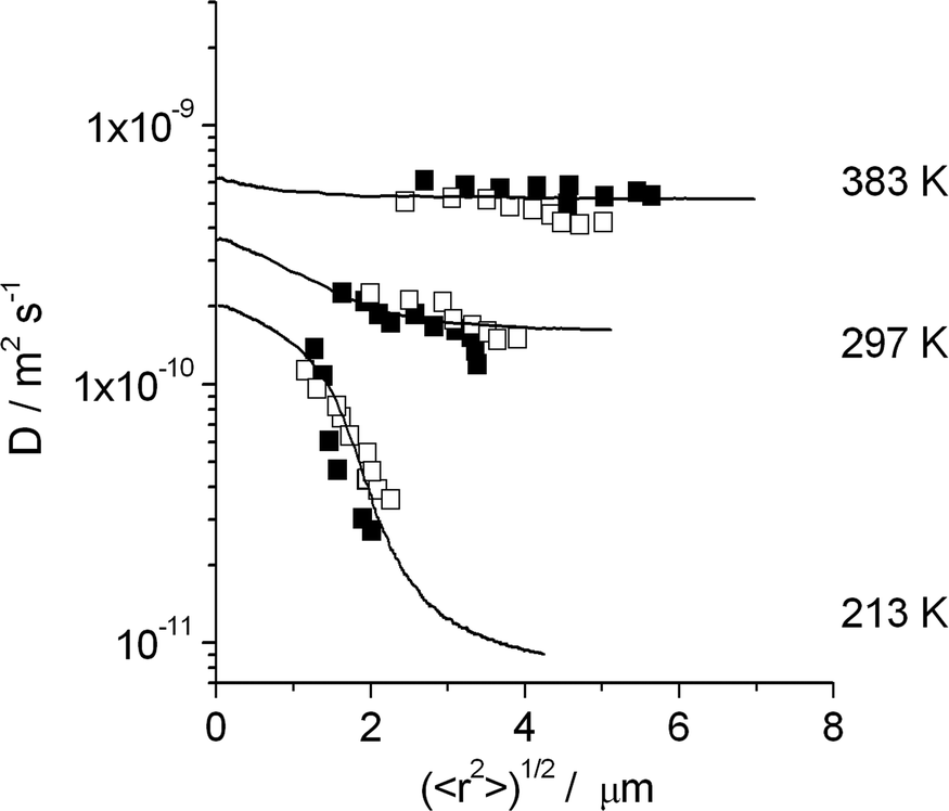 | ||
| Fig. 7 Dependencies of the diffusion coefficients of n-butane in silicalite-1 on the root mean square displacements at different temperatures and comparison with the results of dynamic MC simulations for a barrier separation of 3 μm with the assumption that jumps across the barriers occur with an activation energy exceeding that of intracrystalline diffusion by 21.5 kJ mol−1. Filled and open symbols correspond to measurements performed with two different silicalite-1 samples. Reprinted with permission from ref. 95. Copyright©2002 Elsevier. | ||
Fig. 8 introduces PFG NMR into the options for probing transport enhancement in hierarchical pore structures.19 With propane as a probe molecule, the presence of the mesopores in mesoporous zeolite LTA97 is seen to dramatically enhance the efficiency of mass transfer. The diffusivities remain, within the considered time spans from 20 to 200 ms, unaffected by a variation of the observation time – as expected for normal diffusion. Via eqn (7), the molecular displacements covered in this study are estimated to range from 200 nm (purely microporous species, shortest observation time) up to 10 μm (largest mesoporosity, largest observation time). With the diffusivity data for purely microporous LTA (see also ref. 98) and gas kinetic approaches of the mesopore diffusivity based on the adsorption isotherm and the pore size distribution function,24,99eqn (8) (with i referring to, respectively, the microporous and mesoporous phases) proved to serve as a reasonable estimate of the experimentally determined self-diffusivities. PFG NMR thus provides clear evidence that mass transfer of propane in hierarchical zeolite LTA obeys the fast-exchange condition, τmicro ≪ τcryst.
 | ||
| Fig. 8 SEM images of crystals of mesoporous zeolite LTA (top) and self-diffusivities of propane at 25 °C (bottom); squares: purely microporous LTA; circles: mesoporous LTA, volume fraction 0.18; triangles: mesoporous LTA, volume fraction 0.30. Adapted with permission from ref. 19. Copyright©2012 John Wiley and Sons. | ||
The zeolite sample of hierarchical structure as shown in Fig. 8 has also been used to study mass transfer in the two subspaces with suppressed mutual exchange.18,22 In this way, mass transfer in hierarchical zeolite LTA if confined exclusively to micropore space was found to be dramatically decreased in comparison with the purely microporous zeolite. Thus, in situations where mass transfer in the mesopores is excluded by coke deposits, mass transfer in mesoporous samples may become even slower than in the purely microporous samples.
Since PFG NMR usually records displacements well above 100 nm, it will fail, in general, to provide “microscopic” information about mass transfer in hierarchical pore spaces. This becomes in particular true if the extensions Rmicro of the purely microporous phase in the hierarchical material (eqn (23)) are far below the measuring range attainable by PFG NMR. Attaining values of Rmicro as small as possible is clearly one of the main goals of fabricating mesoporous zeolites and related materials, as the prime prerequisite for acceleration of mass transfer under the slow-exchange conditions (eqn (28)). Examples of hierarchical host–guest systems subject to the condition of slow exchange include branched alkanes in mesoporous zeolite MFI100 and n-alkanes in mesoporous SAPO-34.22,49
Being sensitive to molecular displacements over a few nanometers,101,102 quasi-elastic neutron scattering (QENS) may become the technique of choice for diffusion measurement over very small distances where PFG NMR fails. Thus, by QENS diffusion studies within the micropores of hierarchical materials, possible differences in comparison with the propagation rate in the purely microporous material would immediately become accessible to measurement. QENS has already been shown to be a highly sensitive tool for measuring both self-diffusion (incoherent scattering) and transport diffusion (coherent scattering) in nanoporous materials.69,103–105 In systems where the probe molecules trace essentially the same structural features from nanometers as relevant for QENS up to micrometers as relevant for PFG NMR, both techniques yield consistent information.106,107 QENS diffusivities that substantially exceed the PFG NMR values have also been observed for some systems, suggesting the existence of additional resistances with spacing between the two ranges of measurement.107,108
5. Experimental measurement and molecular modelling
5.1 Impact of measurement on theory
Diffusion in nanoporous materials is among the topics which nicely illustrate the mutual benefit of experimental measurement and theoretical prediction. Thus it was probably not by mere coincidence, that the search for possible reasons of the discrepancy between micro- and macroscopic measurements of zeolitic diffusion observed in this time80,109 was accompanied by an increasing number of papers dealing with the prediction of intracrystalline diffusivities based on established host–guest and guest–guest interaction potentials.29,110 While the information provided by the simulations was helpful in assessing the reliability of the measurement results,111 notably including the information provided on diffusion anisotropy,112 the experimental data became, in turn, an important criterion of reliability for the results of molecular modelling. This interrelation still holds true. An example of such cooperative studies is provided by ref. 104 with reference to MD simulations and QENS measurements. No doubt the reliability of theoretical predictions will further increase with the number of systems for which compatibility between the results of measurement and simulation is demonstrated. Generalizing from the results reported so far, one may say that molecular simulations of nanopore diffusion generally work well for relatively open pore systems but often fail for small pore systems where repulsive forces play a dominant role. Improvements in our understanding and ability to model repulsive forces are clearly required before substantial further progress can be achieved for such systems.As a particular challenge for simulation one may also identify the need for reliable prediction of surface resistances, based on MD simulations of the passage between intra- and intercrystalline spaces.113 With eqn (21) and (22), transport enhancement is seen to be related with the pursuit of small spatial extensions which, in turn, notably reduce the options for experimental measurement of such resistances.
As a phenomenon of non-equilibrium thermodynamics, diffusion in nanoporous materials cannot, in general, be expected to be predictable solely from their adsorption (i.e. equilibrium) properties. It is therefore important to emphasize that, under certain conditions, such predictions are indeed possible, without any need for extensive simulations. This is in particular the case when the individual cages of the pore space are connected through “windows” small enough so that any molecular passage may be assumed to be an “infrequent event” (see, e.g., chapter 9 in ref. 5 and discussion in Section 2). IRM makes it possible to determine both transport diffusivities and self-diffusivities in the same device (by measuring both uptake and release and tracer exchange rates), thus ensuring that the data are directly comparable. An example of such a study is given in the following sub-section.
5.2 Diffusivities predicted from equilibrium adsorption
Fig. 9 provides such a comparison for methanol, ethanol and ethane in crystals of ZIF-8 type MOFs.72 The data presented show the expected coincidence between corrected and self-diffusivity and are in complete agreement with the predictions of eqn (13), with D0 ≡ D. We note in particular: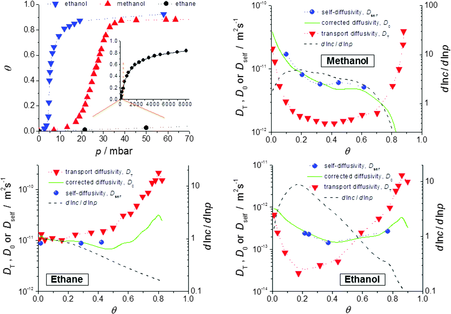 | ||
Fig. 9 Self-diffusivities (Dself) and transport diffusivities (Dt) of methanol (b), ethane (c) and ethanol (d) in a nanoporous host (metal–organic framework (MOF) of type ZIF-8) and self-diffusivities predicted viaeqn (13), with D0 ≡ D from the transport diffusivities and the inverse  of the thermodynamic factor as derived from the respective adsorption isotherms (a), plotted as a function of fractional loading of the thermodynamic factor as derived from the respective adsorption isotherms (a), plotted as a function of fractional loading  . Adapted with permission from ref. 72. Copyright©2010 American Physical Society. . Adapted with permission from ref. 72. Copyright©2010 American Physical Society. | ||
(i) Transport and self-diffusivities approach each other in the limit of small concentration, as is required since any distinction between equilibrium and non-equilibrium phenomena becomes meaningless for negligible guest–guest interaction.114
(ii) Differently shaped isotherms (methanol: S-shaped; ethane: Langmuir type) yield different values for the thermodynamic correction factors (dlnp/dlnc). Thus the transport diffusivity is smaller (methanol) or larger (ethane) than the self-diffusivity over essentially the whole range of concentrations covered. With ethanol the transport diffusivity is found to be smaller for low and larger for high concentrations. The influence of mutual attraction of the guest molecules at low loadings is thus seen to be over-compensated by their competition for free space at high concentrations.
(iii) At the upper limit of the considered range of loadings, the transport diffusivities of both ethane and ethanol are found to decrease. According to eqn (13), the contribution of the thermodynamic factor would lead to transport diffusivities increasing rather than decreasing with increasing concentration. The influence of the thermodynamic factor on the transport diffusivity is thus seen to be overcompensated by the loading dependence of the corrected (or self-) diffusivity.
(iv) Similar observations have recently been made with short-length hydrocarbons in SAPO-34.115 Such a behavior might be caused by guest-induced lattice variations which are well known to occur with nanoporous materials,67,116
Considering the passage through the windows between adjacent cavities as an “infrequent event”, by following the classical theory of absolute reaction rates,73,117 the mean jump rate out of a cage into an adjacent one is easily seen to obey the simple proportionality
 | (35) |
Eqn (35) holds also under conditions of multicomponent adsorption, now with the pressure pi(c1…cn) becoming a function of the concentrations of all components. By considering the net flux between adjacent cages under the influence of an overall concentration gradient, for a two-component system, e.g., the elements of the diffusion matrix (eqn (11)) may be shown to be given by73
 | (36) |
5.3 “Uphill” diffusion and overshooting
In recent uptake studies of light hydrocarbons by DDR-type zeolites it has been demonstrated that IFM may even be applied to selectively record concentration profiles during multicomponent adsorption provided that there is a sufficiently large difference between the diffusivities of the various components. These options are illustrated in further detail in Fig. 10 which shows the profiles measured during the adsorption of mixtures of propene/ethane and ethane/CO2. During the measurement of propene and ethane profiles (top figures), on account of its very slow diffusion, the propene concentration profile may be assumed to remain invariant during the uptake of ethane. Fig. 10(b) shows the ethane profiles during uptake under the influence of an external ethane atmosphere. Prior to the experiment the initially empty crystal was exposed to a propene atmosphere for over 7 hours, yielding the concentration profile shown in Fig. 10(a). Remarkably, after about 10 min, when the ethane concentration appears to be essentially uniform over the crystal, ethane continues to enter the pore space, now having to diffuse “uphill”. However, this behavior becomes immediately understandable when one considers the gradient of chemical potential (which depends on the concentrations of both components). Although at this point in time the concentration of ethane is essentially uniform, as a result of the presence of propene, there is still a gradient of chemical potential towards the center of the crystal, so ethane continues to diffuse in that direction leading to an “overshoot” in the ethane loading (i.e. a transient concentration in excess of the equilibrium level). This phenomenon is well known since the classical studies of Habgood119,120 (see also ref. 91 and 121) but it was only with the introduction of microimaging that uphill fluxes could be recorded directly.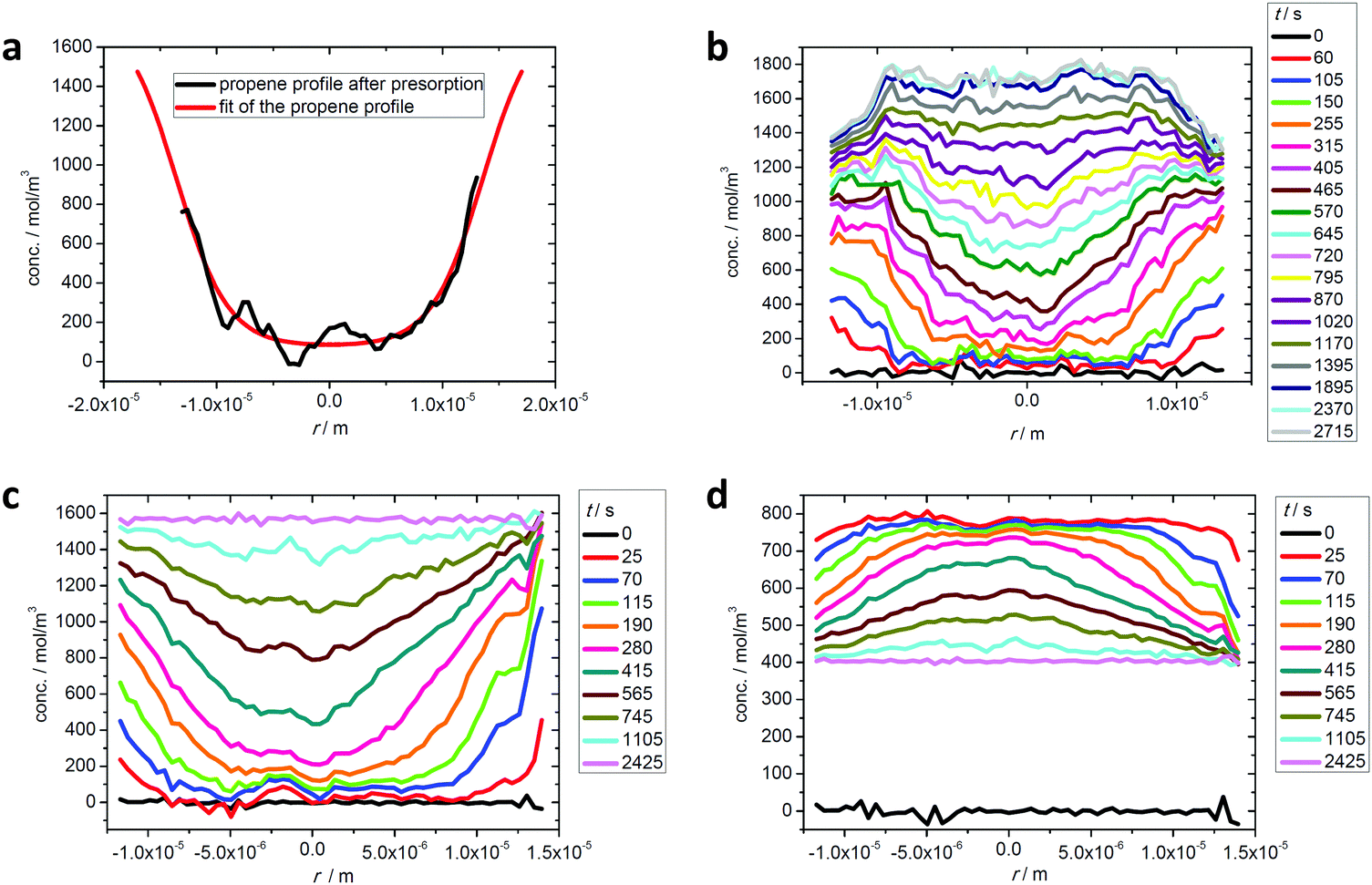 | ||
| Fig. 10 Intracrystalline transient profiles of ethane uptake (b) after propene presorption over a time span of 7 hours, with the final propene profile shown in (a), and transient profiles of ethane (c) and CO2 (d) during two-component uptake on a DDR-type zeolite crystal at room temperature. Reprinted with permission from ref. 73, CC BY 4.0. | ||
Over longer time spans, propene equilibrates throughout the pore space so that, with decreasing slope in the propene concentration, the gradient of chemical potential for ethane is reversed, with the result that the ethane flux is also reversed and the ethane concentration decreases to its equilibrium value. As a result of the very low diffusivity of propene, experiments on the required time scale would take too long for practical studies. Experiments of this type, however, are possible by considering the uptake of CO2–ethane mixtures, with ethane now as the “slow” component. In fact, with diffusivities in the range of 10−9 m2 s−1 and above,122 CO2 may be assumed to equilibrate essentially instantaneously, reaching its equilibrium concentration as determined by the (external) gas pressure of CO2 and the local ethane concentration. In this way, by correlating the respective partial pressures and concentrations via the Ideal Adsorption Solution theory,123 once again the concentration of both components may be determined separately from each other. Already for the very first profiles, the situation shown in Fig. 10(c) and (d) is similar to the situation shown by the last profile in Fig. 10(b). Thus, the entire process from the initial pressure change until final equilibration has now become accessible to direct observation.
Fig. 11 demonstrates that the simple approximations provided by eqn (35) and (36) provide a reasonable prediction of the experimental data. In fact, the small differences between theory and experiment might even be explained by structural imperfections in the DDR crystal.
 | ||
| Fig. 11 Ethane uptake under two-component adsorption experimentally observed (broken lines) and prediction from mixture adsorption data by transition state theory (eqn (36)) (full lines): as (a) the “slow” component in mixture with CO2 (situation of Fig. 10(c)) and (b) the “fast” component in mixture with propene (situation of Fig. 10(b)). Reprinted with permission from ref. 73, CC BY 4.0. | ||
6. Mass transfer in catalytic and separation processes
To illustrate the practical importance of modelling diffusion processes we present two representative examples, one of a catalytic process and the other a membrane separation.6.1 Catalytic cracking over zeolite Y
Catalytic cracking of linear hydrocarbons is generally carried out over a catalyst containing steam stabilized zeolite Y, often as a mixture of hydrogen and rare earth forms. The catalyst particles are typically of about 50–70 μm diameter, formed from zeolite crystals (1–2 μm) aggregated with a clay binder. The extent to which this important reaction is influenced by micropore and macropore diffusion was investigated by Kortunov et al.6,15Fig. 12(a) shows PFG NMR measurements of both intracrystalline and intraparticle diffusivities for n-octane. At 300 K these diffusivities are of similar magnitude but since the effective activation energy for macropore diffusion (approximately equal to the heat of adsorption) is higher than the activation energy for intracrystalline diffusion (≈33 kJ mol−1), at the reaction temperature (≈800 K) the intraparticle diffusivity is about a hundred times greater than the intracrystalline diffusivity. However, the relative importance of intraparticle and intracrystalline diffusion (with the respective diffusivities Dmacro and Dmicro) depends on the ratio of the Thiele moduli for particle and crystal (ϕp and ϕc) which is given by: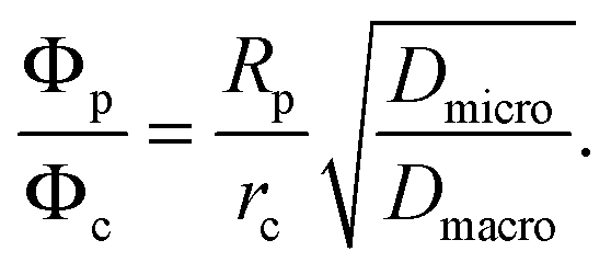 | (37) |
 | ||
| Fig. 12 Performance of zeolite Y based cracking catalysts. (a) Temperature dependence of intracrystalline and intraparticle diffusivities; (b) correlation of catalyst performance at 803 K with intraparticle diffusivity. Reprinted with permission from ref. 6. Copyright©2005 Elsevier. | ||
Fig. 12(b) shows the variation in conversion with intraparticle diffusivity for four different zeolite Y based catalysts of similar particle size, operated at the same temperature (803 K), feed composition and space time. The improvement in performance with increasing intraparticle diffusivities is clearly apparent and provides convincing evidence of intraparticle diffusion limitation under reaction conditions.
6.2 Separation by permeation through a silicalite membrane
As a second example we refer to the perm-selective separation of CH4/C2H6 mixture using a supported silicalite membrane, studied by van de Graaf et al.124 Their experimental data (flux and selectivity vs. feed composition) are shown in Fig. 13 together with the theoretical curves calculated from the Maxwell–Stefan model (eqn (16)). The equilibrium isotherm is represented by the extended Langmuir model with parameters derived from the single component data. The D0 values are also obtained from single component data and the mutual diffusivities (Đij) are estimated from the single component diffusivities using the Vignes correlation.35 It is clear that the theoretical curves calculated in this way provide an excellent representation of the observed performance of the membrane. Also shown in Fig. 13 are the theoretical curves calculated from the simplified Habgood model119,120 in which the cross coefficient terms are neglected (Đij in eqn (16) → ∞). For many small pore systems this model provides a satisfactory approximation but it is evident that this is not true for this system. This is not surprising since the nominal pore diameter of silicalite (≈0.6 nm) is significantly greater than the molecular diameters of both ethane and methane. | ||
| Fig. 13 Separation of ethane–methane mixtures by permeation through a silicalite membrane. (a) Flux and (b) selectivity vs. feed composition. Continuous lines show the predictions derived from the Maxwell–Stefan model using single component diffusivities and equilibrium parameters with mutual diffusivities estimated from the Vignes correlation.35 Broken lines show the predictions derived from the simplified (Habgood) model in which the mutual diffusion terms are neglected. Reprinted with permission from van de Graaf et al.124 Copyright©1999 John Wiley and Sons. | ||
7. Perspectives
Provided that there are no significant convective flows, transport in a uniform or statistically uniform nanoporous structure can generally be accurately described by the Fickian model. However, since the fundamental driving force for diffusive transport is the gradient of chemical potential, conformity with Fick's equations with a constant diffusivity is observed only when the relationship between concentration and thermodynamic activity is linear (i.e. within the Henry's law region). In that situation transport and self-diffusivities are numerically equal. When the equilibrium isotherm is non-linear the Fickian model still applies but the diffusivity becomes a function of concentration. The pattern of concentration dependence is determined mainly by the form of the equilibrium isotherm. For a favorable (Type 1) isotherm the transport diffusivity is greater than the self-diffusivity and increases with concentration due to the increasing thermodynamic factor. The inverse of this pattern is observed if the isotherm is unfavorable (Type 3) but this is relatively uncommon. For small pore systems the thermodynamically corrected diffusivity is approximately equal to the self-diffusivity. Its concentration dependence is less pronounced than that of the transport diffusivity. With increasing pore sizes, both the corrected and self-diffusivities (now generally deviating from each other) may follow quite different patterns of concentration dependence,28,29,103 often in conformity with the Reed- Ehrlich model.125Surface barriers are common, especially in small crystals (as a consequence of the increased area/volume ratio). In many cases they appear to arise from the complete blocking of the entrances to many of the pores, rather than from partial obstruction of the entrances or a decrease in pore diameter near the surface. For such systems the activation energies of the surface permeability and the internal diffusivity are the same and the ratio of these two resistances is independent of concentration and the same for different probe molecules. The modelling of systems in which both surface and internal resistances are important requires only a modification of the surface boundary condition (as noted by Crank13).
Internal barriers are also quite common and are generally attributable to dislocation of the pores by structural defects. The Fickian model can also be used to describe such systems but the apparent diffusivity depends on the scale of the measurements. The true “micropore” diffusivity characteristic of the ideal pore system will be observed only at length scales substantially smaller than the average distance between barriers. If the scale of the measurement is large relative to the barrier spacing the apparent diffusivity approximately follows the reciprocal addition rule (eqn (19)).
Commercial catalysts and adsorbents generally consist of small microporous crystals formed into a macro/mesoporous pellet. The transport behavior of such materials can usually be represented by the dual resistance diffusion model45,46 and the relative importance of the macro- and microscale resistances depends on the ratio of the diffusional time constants. The Fickian model can also be applied to more complex hierarchical pore systems, provided that the rate of interchange between the regions is sufficiently rapid. When the exchange rate is slow the Fickian model will no longer apply and there may be no alternative to molecular simulation.
PFG NMR offers the unique advantage that the length scale of the measurement can be adjusted arbitrarily over a wide range (100 nm–100 μm), thus making it possible to detect the presence of internal barriers and, under favorable conditions, to determine both the micro- and macroscale diffusivities in a hierarchical pore structure. Microimaging techniques, especially interference microscopy, allow direct measurement of the transient concentration profiles thus allowing more complex systems to be studied in detail. However, such techniques are time consuming and therefore unsuitable for routine characterization. For that purpose the ZLC technique has found increasing acceptance as the method of choice.
The Fickian theory and indeed the experimental techniques noted here all assume an isothermal system. This is always fulfilled for self-diffusion but, since heats of adsorption are often quite large, this condition may be violated in uptake rate or transient profile measurements. Simple calculations126 show that for measurements with a single crystal (or a few isolated crystals) heat transfer is always sufficiently rapid, even under stagnant conditions, to validate the isothermal approximation. However, this is not necessarily true for larger samples and for measurements with pelleted adsorbents. For such systems it is important to check carefully for the intrusion of heat effects since such intrusion is not always obvious from the shape of the uptake curve or the concentration profile.
Performance enhancement by reducing the diffusional resistance is presently leading to a new generation of nanoporous materials accommodating complex, integrated pore networks. Overall mass transfer in such systems obviously depends on a multitude of parameters, being determined by the geometry of the pore space and the host–guest interaction as a function of this geometry and surface chemistry. Thus, depending on the nature of the guest molecule under consideration, different ranges within the porous materials may contribute quite differently to overall molecular transport.
Quantitation of these contributions by experimental measurement is among the challenges of current research. Such efforts should benefit from the synergy attainable by combining the information provided by the microscopic techniques of single-particle tracking61–63,87,127 and of ensemble measurement such as Quasi-Elastic Neutron Scattering,102–104 PFG NMR and microimaging. More extensive measurements of these kinds are also needed to validate the theoretical predictions from molecular simulations. Just as theoretical modelling is indispensable for comprehensive understanding and for suggesting new approaches to performance enhancement, the value of any theoretical prediction becomes questionable if it is not verified experimentally.
Acknowledgements
In this review we have attempted to trace the development of diffusion studies in nanoporous materials over the last several decades with brief comments on some challenges for the immediate future. During this research we have had the privilege and pleasure to contact and collaborate with many individuals including our own highly esteemed mentors and many diligent students as well as professional colleagues. Since we cannot thank them all individually, we are pleased to dedicate this review to Professor Francois Fajula in recognition of both his own contributions to this field and his many contributions to the research community, as well as for many stimulating and encouraging personal discussions. Special thanks go to Alexander Lauerer who, in addition to completing his PhD thesis, has looked after the technical completion of this contribution. We also thank the National Science Foundations of Germany and the US, the Alexander von Humboldt Foundation, Fonds der Chemischen Industrie and ExxonMobil corporation for financial support over many years.References
- F. Jüttner, Z. Phys. Chem., 1909, 65, 595 Search PubMed.
- (a) G. Damköhler, Der Chemie-Ingenieur, 1937, 3, 359–488 Search PubMed; (b) G. Damköhler, Int. Chem. Eng., 1988, 28, 132–198 Search PubMed.
- E. W. Thiele, Ing. Eng. Chem., 1939, 31, 916 CrossRef CAS.
- (a) D. M. Ruthven, Ind. Eng. Chem. Res., 2000, 39, 2127–2131 CrossRef CAS; (b) J. Kärger, Adsorption, 2003, 9, 29–35 CrossRef.
- J. Kärger, D. M. Ruthven and D. N. Theodorou, Diffusion in Nanoporous Materials, Wiley-VCH, Weinheim, 2012 Search PubMed.
- J. Kärger and S. Vasenkov, Microporous Mesoporous Mater., 2005, 85, 195–206 CrossRef.
- J. Kärger, M. Kocirik and A. Zikanova, J. Colloid Interface Sci., 1981, 84, 240–249 CrossRef.
- P. Zeigermann, S. Naumov, S. Mascotto, J. Kärger, B. M. Smarsly and R. Valiullin, Langmuir, 2012, 28, 3621–3632 CrossRef CAS PubMed.
- N. Wakao and J. M. Smith, Chem. Eng. Sci., 1962, 17, 825–834 CrossRef CAS.
- E. L. Cussler, Diffusion: Mass Transfer in Fluid Systems, Cambridge University Press, Cambridge, 3rd edn, 2009 Search PubMed.
- J. Kärger, Adv. Colloid Interface Sci., 1985, 23, 129–148 CrossRef.
- D. Schneider, D. Kondrashova, R. Valiullin, A. Bunde and J. Kärger, Chem. Ing. Tech., 2015, 87, 1794–1809 CrossRef CAS.
- J. Crank, The Mathematics of Diffusion, Clarendon Press, Oxford, 1975 Search PubMed.
- (a) P. Weisz, J. Catal., 1962, 1, 399–406 CrossRef CAS; (b) C. N. Satterfield and T. K. Sherwood, The Role of Diffusion in Catalysis, Addison-Wesley, Reading, MA, 1963 Search PubMed; (c) E. E. Petersen, Chemical Reaction Analysis, Prentice-Hall, Englewood Cliffs, NJ, 1965 Search PubMed.
- P. Kortunov, S. Vasenkov, J. Kärger, M. F. Elia, M. Perez, M. Stöcker, G. K. Papadopoulos, D. Theodorou, B. Drescher, G. McElhiney, B. Bernauer, V. Krystl, M. Kocirik, A. Zikanova, H. Jirglova, C. Berger, R. Gläser, J. Weitkamp and E. W. Hansen, Chem. Mater., 2005, 17, 2466–2474 CrossRef CAS.
- R. Mueller, S. Zhang, C. Zhang, R. Lively and S. Vasenkov, J. Membr. Sci., 2015, 477, 123–130 CrossRef CAS.
- (a) M. Hartmann, Angew. Chem., Int. Ed., 2004, 43, 5880–5882 CrossRef CAS PubMed; (b) C. Bertrand-Drira, X.-W. Cheng, T. Cacciaguerra, P. Trens, G. Melinte, O. Ersen, D. Minoux, A. Finiels, F. Fajula and C. Gerardin, Microporous Mesoporous Mater., 2015, 213, 142–149 CrossRef CAS.
- D. Mehlhorn, R. Valiullin, J. Kärger, K. Cho and R. Ryoo, Microporous Mesoporous Mater., 2012, 164, 273–279 CrossRef CAS.
- D. Mehlhorn, R. Valiullin, J. Kärger, K. Cho and R. Ryoo, ChemPhysChem, 2012, 13, 1495–1499 CrossRef CAS PubMed.
- K. P. Möller and T. Bein, Chem. Soc. Rev., 2013, 42, 3689 RSC.
- B. Coasne, A. Galarneau, C. Gerardin, F. Fajula and F. Villemot, Langmuir, 2013, 29, 7864–7875 CrossRef CAS PubMed.
- M. Rincon Bonilla, T. Titze, F. Schmidt, D. Mehlhorn, C. Chmelik, R. Valiullin, S. K. Bhatia, S. Kaskel, R. Ryoo and J. Kärger, Materials, 2013, 6, 2662–2688 CrossRef.
- (a) R. Valiullin, P. Kortunov, J. Kärger and V. Timoshenko, J. Chem. Phys., 2004, 120, 11804–11814 CrossRef CAS PubMed; (b) R. Valiullin, M. Dvoyashkin, P. Kortunov, C. Krause and J. Karger, J. Chem. Phys., 2007, 126, 54705–54706 CrossRef PubMed; (c) R. Valiullin and M. Dvoyashkin, Adsorption, 2007, 13, 239–245 CrossRef CAS; (d) W. D. Einicke, D. Enke, M. Dvoyashkin, M. Valiullin and R. Gläser, Materials, 2013, 6, 3688–3709 CrossRef CAS.
- M. Dvoyashkin, M. Valiullin and J. Kärger, Phys. Rev. E: Stat., Nonlinear, Soft Matter Phys., 2007, 75, 41202 CrossRef PubMed.
- H. Mehrer, Diffusion in solids, Springer, Berlin, 2007 Search PubMed.
- P. V. Danckwerts, in Diffusion Processes, ed. A. V. Chadwick, W. M. Muir and F. L. Swinton, Gordon and Breach, London, 1971, vol. 2, p. 45 Search PubMed.
- S. R. DeGroot and P. Mazur, Non-Equilibrium Thermodynamics, Elsevier, Amsterdam, 1962 Search PubMed.
- J. Kärger and H. Pfeifer, Zeolites, 1987, 7, 90–107 CrossRef.
- F. J. Keil, R. Krishna and M. O. Coppens, Rev. Chem. Eng., 2000, 16, 71–197 CAS.
- (a) R. M. Barrer and W. Jost, Trans. Faraday Soc., 1949, 45, 928–930 RSC; (b) R. M. Barrer, Adv. Chem. Ser., 1971, 102, 1–36 CrossRef CAS; (c) J. Kärger, Surf. Sci., 1973, 36, 797–801 CrossRef; (d) D. Ruthven, in Physical Adsorption: Experiment, Theory and Applications, ed. J. Fraissard and C. W. Conner, Dordrecht/Boston/London, 1997, vol. 491, pp. 241–260 Search PubMed; (e) D. M. Ruthven, in Adsorption and Diffusion, ed. H. G. Karge and J. Weitkamp, Springer, Berlin, Heidelberg, 2008, vol. 7, pp. 1–43 Search PubMed; (f) R. Krishna, Chem. Soc. Rev., 2012, 41, 3099–3118 RSC.
- (a) B. Coughlan and M. A. Keane, Zeolites, 1991, 11, 483–490 CrossRef CAS; (b) A. Fick, Annu. Rev. Phys. Chem., 1855, 94, 59–86 CrossRef.
- (a) J. C. Maxwell, Philos. Mag., 1860, 19, 19–32 Search PubMed; (b) J. C. Maxwell, Philos. Mag., 1860, 20, 21–37 Search PubMed.
- J. Stefan, Wien Ber., 1872, 65, 323 Search PubMed.
- (a) R. Krishna and J. A. Wesselingh, Chem. Eng. Sci., 1990, 45, 1779–1791 CrossRef CAS; (b) R. Krishna and J. A. Wesselingh, Chem. Eng. Sci., 1997, 52, 861 CrossRef CAS.
- A. Vignes, Ind. Eng. Chem. Fundam., 1966, 189–199 CAS.
- C. Chmelik, J. van Baten and R. Krishna, J. Membr. Sci., 2012, 397–398, 87–91 CrossRef CAS.
- D. Paschek and R. Krishna, Chem. Phys. Lett., 2001, 333, 278–284 CrossRef CAS.
- H. S. Carslaw and J. C. Jaeger, Conduction of heat in solids, Oxford Science Publications, Oxford, 2004 Search PubMed.
- (a) S. J. Reitmeier, O. C. Gobin, A. Jentys and J. A. Lercher, J. Phys. Chem. C, 2009, 113, 15355–15363 CrossRef CAS; (b) S. T. Reitmeier, O. C. Gobin, A. Jentys and J. A. Lercher, Angew. Chem., Int. Ed., 2009, 48, 533–538 CrossRef CAS PubMed; (c) O. C. Gobin, S. J. Reitmeier, A. Jentys and J. A. Lercher, J. Phys. Chem. C, 2011, 115, 1171–1179 CrossRef CAS; (d) A. R. Teixeira, X. Qi, W. Conner, T. J. Mountziaris, W. Fan and P. J. Dauenhauer, Chem. Mater., 2015, 27, 4650–4660 CrossRef CAS.
- A. R. Teixeira, X. Qi, C.-C. Chang, W. Fan, C. W. Conner and P. J. Dauenhauer, J. Phys. Chem. C, 2014, 118, 22166–22180 CAS.
- (a) M. Kocirik and A. Zikanova, Ind. Eng. Chem. Fundam., 1975, 13, 347–350 CrossRef; (b) M. M. Dubinin, I. T. Erashko, O. Kadlec, V. I. Ulin, A. M. Voloshchuk and P. P. Zolotarev, Carbon, 1975, 13, 193–200 CrossRef CAS.
- R. M. Barrer, Zeolites and Clay Minerals as Sorbents and Molecular Sieves, Academic Press, London, 1978 Search PubMed.
- H. S. Sherry, Adv. Chem., 1974, 101, 350–379 Search PubMed.
- (a) S. Han, Y. Wei, C. Valente, I. Lagzi, J. J. Gassensmith, A. Coskun, J. F. Stoddart and B. A. Grzybowski, J. Am. Chem. Soc., 2010, 132, 16358–16361 CrossRef CAS PubMed; (b) S. Han, T. M. Hermans, P. E. Fuller, Y. Wei and B. A. Grzybowski, Angew. Chem., Int. Ed., 2012, 51, 2662–2666 CrossRef CAS PubMed.
- E. Ruckenstein, A. S. Vaidyanathan and G. R. Youngquist, Chem. Eng. Sci., 1971, 26, 1305–1318 CrossRef CAS.
- Y. H. Ma and T. Y. Lee, AIChE J., 1976, 22, 147–152 CrossRef CAS.
- L. K. Lee, AIChE J., 1978, 24, 531–533 CrossRef CAS.
- (a) M. Choi, H. S. Cho, R. Srivastava, C. Venkatesan, D. H. Choi and R. Ryoo, Nat. Mater., 2006, 5, 718–723 CrossRef CAS PubMed; (b) A. Galarneau, J. Iapichella, K. Bonhomme, F. Di Renzo, P. Kooyman, O. Terasaki and F. Fajula, Adv. Funct. Mater., 2006, 16, 1657–1667 CrossRef CAS; (c) G. Wang and M. O. Coppens, Chem. Eng. Sci., 2010, 65, 2344–2351 CrossRef CAS; (d) I. I. Ivanova and E. E. Knyazeva, Chem. Soc. Rev., 2013, 42, 3671 RSC.
- F. Schmidt, S. Paasch, E. Brunner and S. Kaskel, Microporous Mesoporous Mater., 2012, 164, 214–221 CrossRef CAS.
- D. Mcqueen, F. Fajula, R. Dutartre, L. V. C. Rees and P. Schulz, Stud. Surf. Sci. Catal., 1994, 84, 1339–1346 CrossRef CAS.
- (a) Mesoporous Zeolites. Preparation, Characterization and Applications, ed. J. García-Martínez and K. Li, Wiley-VCH, Weinheim, 1st edn, 2015 Search PubMed; (b) M.-O. Coppens, Curr. Opin. Chem. Eng., 2012, 1, 281–289 CrossRef CAS.
- S. M. Rao and M.-O. Coppens, Chem. Eng. Sci., 2012, 83, 66–76 CrossRef CAS.
- M.-O. Coppens and T. T. Tsotsis, Curr. Opin. Chem. Eng., 2014, 5, vii–ix CrossRef.
- (a) S. Kirkpatrick, Rev. Mod. Phys., 1973, 45, 574 CrossRef; (b) M. R. Bonilla and S. K. Bhatia, Langmuir, 2012, 28, 517–533 CrossRef CAS PubMed; (c) X. Liu, D. Newsome and M.-O. Coppens, Microporous Mesoporous Mater., 2009, 125, 149–159 CrossRef CAS.
- (a) G. K. Papadokostaki and D. N. Theodorou, Diffusion Fundamentals, 2005, 2, 1–25 Search PubMed; (b) G. K. Papadopoulos, D. N. Theodorou, S. Vasenkov and J. Kärger, J. Chem. Phys., 2007, 126, 94702 CrossRef PubMed.
- (a) V. Iyengar and M.-O. Coppens, Chem. Eng. Sci., 2004, 59, 4747–4753 CrossRef CAS; (b) M. O. Coppens and V. Iyengar, Nanotechnology, 2005, 16, S442–S448 CrossRef PubMed.
- G. Ye, X. Duan, K. Zhu, X. Zhou, M.-O. Coppens and W. Yuan, Chem. Eng. Sci., 2015, 132, 108–117 CrossRef CAS.
- (a) D. M. Ruthven, L. K. Lee and H. Yucel, AIChE J., 1980, 26, 16–23 CrossRef CAS; (b) H. Yucel and D. M. Ruthven, J. Chem. Soc., Faraday Trans. I, 1980, 76, 60 RSC; (c) H. Yucel and D. M. Ruthven, J. Chem. Soc., Faraday Trans. I, 1980, 76, 71 RSC.
- M. Eic and D. M. Ruthven, Zeolites, 1988, 8, 40–45 CrossRef CAS.
- X. Hu, S. Brandani, A. I. Benin and R. R. Willis, Ind. Eng. Chem. Res., 2015, 54, 6772–6780 CrossRef CAS.
- B. M. Weckhuysen, Angew. Chem., Int. Ed., 2009, 48, 4910–4943 CrossRef CAS PubMed.
- In situ characterization of heterogeneous catalysts, ed. B. M. Weckhuysen, themed issue Chem. Soc. Rev., 2010, 39(12), 2010.
- Single particle tracking and single molecule energy transfer, ed. C. Bräuchle, D. C. Lamb and J. Michaelis, Wiley-VCH, Weinheim, 2010 Search PubMed.
- U. Schemmert, J. Kärger, C. Krause, R. A. Rakoczy and J. Weitkamp, Europhys. Lett., 1999, 46, 204–210 CrossRef CAS.
- (a) G. Müller, T. F. Narbeshuber, G. Mirth and J. A. Lercher, J. Phys. Chem. B, 1994, 98, 7436–7439 CrossRef; (b) C. Chmelik, PhD thesis, Leipzig University, 2007; (c) F. Schueth, J. Phys. Chem., 1992, 96, 7493–7496 CrossRef CAS.
- C. Chmelik and J. Kärger, Chem. Soc. Rev., 2010, 39, 4864–4884 RSC.
- J. Kärger, T. Binder, C. Chmelik, F. Hibbe, H. Krautscheid, R. Krishna and J. Weitkamp, Nat. Mater., 2014, 13, 333–343 CrossRef PubMed.
- J. Kärger, ChemPhysChem, 2015, 16, 24–51 CrossRef PubMed.
- I. Déroche, S. Rives, T. Trung, Q. Yang, A. Ghoufi, N. A. Ramsahye, P. Trens, F. Fajula, T. Devic, C. Serre, G. Férey, H. Jobic and G. Maurin, J. Phys. Chem. C, 2011, 115, 13868–13876 Search PubMed.
- (a) A. Martucci, M. Guzman-Castillo, F. Di Renzo, F. Fajula and A. Alberti, Microporous Mesoporous Mater., 2007, 104, 257–268 CrossRef CAS; (b) T. K. Trung, P. Trens, N. Tanchoux, S. Bourrelly, P. L. Llewellyn, S. Loera-Serna, C. Serre, T. Loiseau, F. Fajula and G. Férey, J. Am. Chem. Soc., 2008, 130, 16926–16932 CrossRef CAS PubMed.
- (a) P. Kortunov, C. Chmelik, J. Kärger, R. A. Rakoczy, D. M. Ruthven, Y. Traa, S. Vasenkov and J. Weitkamp, Adsorption, 2005, 11, 235–244 CrossRef CAS; (b) L. Gueudré, T. Binder, C. Chmelik, F. Hibbe, D. M. Ruthven and J. Kärger, Materials, 2012, 5, 721–740 CrossRef.
- C. Chmelik, H. Bux, J. Caro, L. Heinke, F. Hibbe, T. Titze and J. Kärger, Phys. Rev. Lett., 2010, 104, 85902 CrossRef PubMed.
- A. Lauerer, T. Binder, C. Chmelik, E. Miersemann, J. Haase, D. M. Ruthven and J. Kärger, Nat. Commun., 2015, 6, 7697 CrossRef CAS PubMed.
- P. Kortunov, L. Heinke, S. Vasenkov, C. Chmelik, D. B. Shah, J. Kärger, R. A. Rakoczy, Y. Traa and J. Weitkamp, J. Phys. Chem. B, 2006, 110, 23821–23828 CrossRef CAS PubMed.
- C. Chmelik, L. Heinke, P. Kortunov, J. Li, D. Olson, D. Tzoulaki, J. Weitkamp and J. Kärger, ChemPhysChem, 2009, 10, 2623–2627 CrossRef CAS PubMed.
- D. R. Garg and D. M. Ruthven, Chem. Eng. Sci., 1972, 27, 417–423 CrossRef CAS.
- (a) D. Tzoulaki, L. Heinke, J. Li, H. Lim, D. Olson, J. Caro, R. Krishna, C. Chmelik and J. Kärger, Angew. Chem., Int. Ed., 2009, 48, 3525–3528 CrossRef CAS PubMed; (b) F. Hibbe, C. Chmelik, L. Heinke, S. Pramanik, J. Li, D. M. Ruthven, D. Tzoulaki and J. Kärger, J. Am. Chem. Soc., 2011, 133, 2804–2807 CrossRef CAS PubMed.
- L. Heinke and J. Kärger, Phys. Rev. Lett., 2011, 106, 74501 CrossRef PubMed.
- (a) O. K. Dudko, A. M. Berezhkovskii and G. H. Weiss, J. Chem. Phys., 2004, 121, 11283–11288 CrossRef CAS PubMed; (b) C. Tuck, Effective medium theory, Oxford University Press, Oxford, 1999 Search PubMed.
- J. Kärger and D. M. Ruthven, Zeolites, 1989, 9, 267–281 CrossRef.
- D. M. Ruthven, S. Brandani and M. Eic, in Adsorption and Diffusion, ed. H. G. Karge and J. Weitkamp, Springer, Berlin, Heidelberg, 2008, vol. 7, pp. 45–85 Search PubMed.
- F. Hibbe, J. Caro, C. Chmelik, A. Huang, T. Kirchner, D. Ruthven, R. Valiullin and J. Kärger, J. Am. Chem. Soc., 2012, 134, 7725–7732 CrossRef CAS PubMed.
- T. Titze, C. Chmelik, J. Kullmann, L. Prager, E. Miersemann, R. Gläser, D. Enke, J. Weitkamp and J. Kärger, Angew. Chem., Int. Ed., 2015, 54, 5060–5064 CrossRef CAS PubMed.
- (a) Z. Liu, P. Moreau and F. Fajula, Appl. Catal., A, 1997, 159, 305–316 CrossRef CAS; (b) A. El Kadib, R. Chimenton, A. Sachse, F. Fajula, A. Galarneau and B. Coq, Angew. Chem., Int. Ed., 2009, 48, 4969–4972 CrossRef CAS PubMed.
- D. Enke, F. Janowski and W. Schwieger, Microporous Mesoporous Mater., 2003, 60, 19–30 CrossRef CAS.
- (a) G. D. Birkhoff, Proc. Natl. Acad. Sci. U. S. A., 1931, 17, 656–660 CrossRef CAS PubMed; (b) A. Lubelski, I. Sokolov and J. Klafter, Phys. Rev. Lett., 2008, 100, 250602 CrossRef PubMed; (c) D. Froemberg and E. Barkai, Phys. Rev. E, 2013, 88, 24101 CrossRef CAS PubMed.
- F. Feil, S. Naumov, J. Michaelis, R. Valiullin, D. Enke, J. Kärger and C. Bräuchle, Angew. Chem., Int. Ed., 2012, 51, 1152–1155 CrossRef CAS PubMed.
- C. Chmelik, D. Enke, P. Galvosas, O. C. Gobin, A. Jentys, H. Jobic, J. Kärger, C. Krause, J. Kullmann, J. A. Lercher, S. Naumov, D. M. Ruthven and T. Titze, ChemPhysChem, 2011, 12, 1130–1134 CrossRef CAS PubMed.
- L. Prager, A. Dierdorf, H. Liebe, S. Naumov, S. Stojanović, R. Heller, L. Wennrich and M. R. Buchmeiser, Chem. – Eur. J., 2007, 13, 8522–8529 CrossRef CAS PubMed.
- P. B. Weisz, Science, 1973, 179, 433–440 CAS.
- T. Titze, C. Chmelik, J. Kärger, J. M. van Baten and R. Krishna, J. Phys. Chem. C, 2014, 118, 2660–2665 CAS.
- (a) K. H. Hausser and H. R. Kalbitzer, NMR in medicine and biology, Springer, Berlin, Heidelberg, New York, 1991 Search PubMed; (b) Interventional Magnetic Resonance Imaging, ed. T. Kahn and H. Busse, Springer, Berlin, Heidelberg, 2012 Search PubMed.
- (a) P. T. Callaghan, Translational Dynamics and Magnetic Resonance, Oxford University Press, Oxford, 2011 Search PubMed; (b) R. Kimmich, Principles of Soft-Matter Dynamics, Springer, London, 2012 Search PubMed.
- (a) P. T. Callaghan and A. Coy, Phys. Rev. Lett., 1992, 68, 3176–3179 CrossRef CAS PubMed; (b) I. Y. Chang, F. Fujara, B. Geil, G. Hinze, H. Sillescu and A. Tolle, J. Non-Cryst. Solids, 1994, 172, 674–681 CrossRef; (c) P. Galvosas, F. Stallmach, G. Seiffert, J. Kärger, U. Kaess and G. Majer, J. Magn. Reson., 2001, 151, 260–268 CrossRef CAS; (d) K. Ulrich, P. Galvosas, J. Kärger and F. Grinberg, Phys. Rev. Lett., 2009, 102, 37801 CrossRef PubMed; (e) M. Dvoyashkin, A. Wang, A. Katihar, J. Zang, G. Yucelen, S. Nair, D. Sholl, C. Bowers and S. Vasenkov, Microporous Mesoporous Mater., 2013, 178, 119–122 CrossRef CAS.
- S. Vasenkov and J. Kärger, Microporous Mesoporous Mater., 2002, 55, 139–145 CrossRef CAS.
- S. Vasenkov, W. Böhlmann, P. Galvosas, O. Geier, H. Liu and J. Kärger, J. Phys. Chem. B, 2001, 105, 5922–5927 CrossRef CAS.
- K. Cho, H. S. Cho, L. C. de Menorval and R. Ryoo, Chem. Mater., 2009, 21, 5664–5673 CrossRef CAS.
- W. Heink, J. Kärger, H. Pfeifer, K. P. Datema and A. K. Nowak, J. Chem. Soc., Faraday Trans., 1992, 88, 3505–3509 RSC.
- (a) J. Kärger and R. Valiullin, Chem. Soc. Rev., 2013, 42, 4172–4197 RSC; (b) R. Valiullin, Annu. Rep. NMR Spectrosc., 2013, 79, 23–72 CrossRef CAS.
- (a) J. C. Groen, W. Zhu, S. Brouwer, S. J. Huynink, F. Kapteijn, J. A. Moulijn and J. Perez-Ramirez, J. Am. Chem. Soc., 2007, 129, 355–360 CrossRef CAS PubMed; (b) F. C. Meunier, D. Verboekend, J.-P. Gilson, J. C. Groen and J. Pérez-Ramírez, Microporous Mesoporous Mater., 2012, 148, 115–121 CrossRef CAS; (c) L. Gueudré, M. Milina, S. Mitchell and J. Pérez-Ramírez, Adv. Funct. Mater., 2014, 24, 209–219 CrossRef.
- H. Jobic, in Catalyst Characterization: Physical Techniques for Solid Materials, ed. B. V. J. C. Imelik, Plenum Press, New York, 1994, pp. 347–376 Search PubMed.
- H. Jobic, in Adsorption and Diffusion, ed. H. G. Karge and J. Weitkamp, Springer, Berlin, Heidelberg, 2008, vol. 7, pp. 207–233 Search PubMed.
- H. Jobic, J. Kärger and M. Bee, Phys. Rev. Lett., 1999, 82, 4260–4263 CrossRef CAS.
- H. Jobic and D. Theodorou, Microporous Mesoporous Mater., 2007, 102, 21–50 CrossRef CAS.
- N. Rosenbach, H. Jobic, A. Ghoufi, T. Devic, M. M. Koza, N. Ramsahye, C. J. Mota, C. Serre and G. Maurin, J. Phys. Chem. C, 2014, 118, 14471–14477 CAS.
- (a) H. Jobic, M. Bee, J. Caro, M. Bülow and J. Kärger, J. Chem. Soc., Faraday Trans., 1989, 85, 4201–4209 RSC; (b) J. Caro, M. Bülow, H. Jobic, J. Kärger and B. Zibrowius, Adv. Catal., 1993, 39, 351–414 CAS.
- H. Jobic, J. Kärger, C. Krause, S. Brandani, A. Gunadi, A. Methivier, G. Ehlers, B. Farago, W. Haeussler and D. M. Ruthven, Adsorption, 2005, 11, 403–407 CrossRef.
- (a) H. Paoli, A. Methivier, H. Jobic, C. Krause, H. Pfeifer, F. Stallmach and J. Kärger, Microporous Mesoporous Mater., 2002, 55, 147–158 CrossRef CAS; (b) H. Jobic, W. Schmidt, C. Krause and J. Kärger, Microporous Mesoporous Mater., 2006, 90, 299–306 CrossRef CAS; (c) A. Feldhoff, J. Caro, H. Jobic, C. B. Krause, P. Galvosas and J. Kärger, ChemPhysChem, 2009, 10, 2429–2433 CrossRef CAS PubMed.
- J. Kärger and D. M. Ruthven, J. Chem. Soc., Faraday Trans. 1, 1981, 77, 1485–1496 RSC.
- (a) S. Yashonath, P. Demontis and M. L. Klein, Chem. Phys. Lett., 1988, 153, 551–556 CrossRef CAS; (b) P. Demontis, E. S. Fois, G. Suffritti and S. Quartieri, J. Phys. Chem., 1990, 94, 4329–4334 CrossRef CAS; (c) R. L. June, A. T. Bell and D. N. Theodorou, J. Phys. Chem., 1990, 94, 8232–8240 CrossRef CAS; (d) S. J. Goodbody, K. Watanabe, D. MacGowan, J. P. B. Walton and N. Quirke, J. Chem. Soc., Faraday Trans., 1991, 87, 1951–1958 RSC; (e) P. Demontis, G. B. Suffritti, S. Quartieri, A. Gamba and E. S. Fois, J. Chem. Soc., Faraday Trans., 1991, 87, 1657–1663 RSC; (f) S. Fritzsche, R. Haberlandt, J. Kärger, H. Pfeifer and K. Heinzinger, Chem. Phys. Lett., 1992, 198, 283–287 CrossRef CAS; (g) R. Q. Snurr, A. T. Bell and D. N. Theodorou, J. Phys. Chem., 1993, 97, 13742–13752 CrossRef CAS; (h) T. J. H. Vlugt, C. Dellago and B. Smit, J. Chem. Phys., 2000, 113, 8791–8799 CrossRef CAS.
- J. Caro, M. Bülow, W. Schirmer, J. Kärger, W. Heink, H. Pfeifer and S. P. Zhdanov, J. Chem. Soc., Faraday Trans. 1, 1985, 81, 2541–2550 RSC.
- (a) U. Hong, J. Kärger, H. Pfeifer, U. Müller and K. K. Unger, Z. Phys. Chem., 1991, 173, 225–234 CrossRef CAS; (b) U. Hong, J. Kärger, R. Kramer, H. Pfeifer, G. Seiffert, U. Müller, K. K. Unger, H. B. Lück and T. Ito, Zeolites, 1991, 11, 816–821 CrossRef CAS.
- (a) J.-M. Simon, J. B. Bellat, S. Vasenkov and J. Kärger, J. Phys. Chem. B, 2005, 109, 13523–13528 CrossRef CAS PubMed; (b) A. F. Combariza and G. Sastre, J. Phys. Chem. C, 2011, 115, 13751–13758 CrossRef CAS; (c) N. E. R. Zimmermann, B. Smit and F. J. Keil, J. Phys. Chem. C, 2010, 114, 300–310 CrossRef CAS; (d) N. E. R. Zimmermann, S. P. Balaji and F. J. Keil, J. Phys. Chem. C, 2012, 116, 3677–3683 CrossRef CAS; (e) N. E. R. Zimmermann, T. J. Zabel and F. J. Keil, J. Phys. Chem. C, 2013, 117, 7384–7390 CrossRef CAS; (f) J.-M. Simon, J.-P. Bellat and J. M. Salazar, Mol. Simul., 2014, 40, 52–57 CrossRef CAS.
- I. Prigogine, The end of certainty, The Free Press, New York, London, Toronto, Sydney, 1997 Search PubMed.
- J. Cousin Saint Remi, A. Lauerer, G. Baron, C. Chmelik, J. Denayer and J. Kärger, Nat. Mater., 2015 DOI:10.1038/nmat4510.
- (a) C. Gücüyener, J. van den Bergh, J. Gascon and F. Kapteijn, J. Am. Chem. Soc., 2010, 132, 17704–17706 CrossRef PubMed; (b) G. Ferey and C. Serre, Chem. Soc. Rev., 2009, 38, 1380–1399 RSC; (c) C. A. Fyfe, H. Strobl, H. Gies and G. T. Kokotailo, Can. J. Chem., 1988, 66, 1942–1947 CrossRef CAS; (d) R. Q. Snurr, A. T. Bell and D. N. Theodorou, J. Phys. Chem., 1994, 98, 5111–5119 CrossRef CAS; (e) O. Tezel and D. Ruthven, J. Colloid Interface Sci., 1990, 139, 581–583 CrossRef CAS.
- (a) S. Gladstone, K. J. Laidler and H. Eyring, The Theory of Rate Processes, New York, 1941 Search PubMed; (b) D. M. Ruthven and R. I. Derrah, J. Chem. Soc., Faraday Trans. 1, 1972, 68, 2332–2343 RSC; (c) J. Kärger, H. Pfeifer and R. Haberlandt, J. Chem. Soc., Faraday Trans. 1, 1980, 76, 1569–1575 RSC.
- C. Chmelik and J. Kärger, Microporous Mesoporous Mater., 2016, 225, 128–132 CrossRef CAS.
- H. W. Habgood, Can. J. Chem., 1958, 36, 1384 CrossRef CAS.
- L. Bertsch and H. W. Habgood, J. Phys. Chem., 1963, 67, 1621–1628 CrossRef CAS.
- (a) J. Kärger and M. Bülow, Chem. Eng. Sci., 1975, 30, 893–896 CrossRef; (b) R. Krishna, Microporous Mesoporous Mater., 2014, 185, 30–50 CrossRef CAS; (c) R. Krishna, Chem. Soc. Rev., 2015, 44, 2812–2836 RSC.
- T. Binder, C. Chmelik, J. Kärger, A. Martinez-Joaristi, J. Gascon, F. Kapteijn and D. M. Ruthven, Microporous Mesoporous Mater., 2013, 180, 219–228 CrossRef CAS.
- A. L. Myers and J. M. Prausnitz, AIChE J., 1965, 11, 121–130 CrossRef CAS.
- J. M. van de Graaf, F. Kapteijn and J. A. Moulijn, AIChE J., 1999, 45, 497–511 CrossRef CAS.
- D. A. Reed and G. Ehrlich, Surf. Sci., 1981, 102, 588 CrossRef CAS.
- L. Heinke, C. Chmelik, P. Kortunov, D. B. Shah, S. Brandani, D. M. Ruthven and J. Kärger, Microporous Mesoporous Mater., 2007, 104, 18–25 CrossRef CAS.
- (a) J. Kirstein, B. Platschek, C. Jung, R. Brown, T. Bein and C. Bräuchle, Nat. Mater., 2007, 6, 303–310 CrossRef CAS PubMed; (b) A. Zürner, J. Kirstein, M. Döblingern, C. Bräuchle and T. Bein, Nature, 2007, 450, 705–709 CrossRef PubMed.
| This journal is © The Royal Society of Chemistry and the Centre National de la Recherche Scientifique 2016 |