A coarse-grained thermodynamic model for the predictive engineering of valence-selective membranes
Received
31st May 2016
, Accepted 28th July 2016
First published on 10th August 2016
Abstract
Membrane-based filtration has shown promise in the treatment of municipal and industrial water supplies. Most existing filtration membranes rely on size-selective rejection mechanisms and do not offer a systematic means to tune the chemistry of the membrane and, in turn, the rejection of solutes based on chemical factors. Technological advancements in copolymer self-assembly have permitted the creation of highly porous membranes through arrested microphase separation. The resulting structures exhibit nanoscale pores whose size and chemistry are controlled by the macromolecular architecture of the copolymer precursors. Here, we examine in detail how the structure and chemistry of charge-functionalized copolymers affect their performance as nanofiltration membranes through experiments and coarse-grained molecular simulation of membranes formed from poly(acrylonitrile-r-oligo(ethylene glycol) methyl ether methacrylate-r-glycidyl methacrylate) (P(AN-r-OEGMA-r-GMA)). Charge-selective moieties were introduced into the membranes through reactions with diamine salts of varying length, enabling these membranes to offer preferential rejection of multivalent ionic species. Using a minimal model, we explore the essential thermodynamics features of salt rejection in these membranes, and develop a model capable of linking the performance of the membranes to their molecular character through measurement of the underlying free energy profile. Our key result is an effective membrane porosity which quantitatively describes experiments for a wide variety of situations after calibrating a single parameter. These results demonstrate that at moderate ion concentrations and flow rates, the selection of ions is driven predominantly by equilibrium thermodynamics. Going forward, the ability of the model to capture the rejection of dissolved solutes can be leveraged to design optimized membranes for targeted performance profiles in silico before undertaking time consuming batteries of Edisonian experiments.
Design, System, Application
The design of effective water treatment membranes with a high degree of charge selectivity is critical to improving the performance of membranes in desalination, decontamination, and reclamation processes. Here, we discuss the application of postfabrication chemical modifications to membranes derived from self-assembled copolymers to improve their salt rejection capabilities. Using pH-sensitive diamine salts to functionalize copolymer membranes, recent works have demonstrated the generation of high efficiency membranes capable of selecting ions based on their valence. The spacer-arm within the diamine salt has a significant effect on throughput properties, but thus far this effect has been difficult to quantify in a theoretical framework. We offer here a minimal model capable of explaining these effects in purely thermodynamic terms, validating versus both spacer length and pH data. In order to guide the future design of membranes, predictions for the charge-selective behavior of the membrane in yet-untested limits are offered. The chief results of this are (a) a method for obtaining a high degree of specificity in charge-based solute rejection, and (b) a computationally cheap model suitable for the predictive engineering of functionalized copolymer membranes.
|
1. Introduction
Selective ion transport is critical to many technologies used to provide sustainable supplies of energy and water. Biological systems, such as the tetrameric cation channels in cellular membranes that can conduct K+ while selecting against Na+ (ref. 1) provide the most exquisite examples of materials capable of transporting ions selectively. Due to their stability and simple processing strategies, synthetic ion-exchange materials are widely used in established (fuel cells and batteries2,3) and emerging energy applications.4,5 These ion-exchange membranes, which possess pores lined by charged moieties, conduct counter-ions (i.e., those with the opposite charge as the membrane) while repelling co-ions (i.e., those with the same charge as the membrane).6 Due to the high efficiencies of some membrane separations,7,8 charge functionalized membrane materials are an attractive option for several applications that produce potable water from contaminated and saline sources. The key metrics of performance for any functional separation membrane are flux and selectivity;9 in water treatment applications this implies that salt and other impurities should be rejected at as high a rate as possible under high-throughput conditions. Reverse osmosis (RO) membranes, which rely on size-selectivity, hinder hydrated ion transport across the membrane, permitting only water to permeate.10,11 RO membranes necessarily reject all dissolved ions to large extents.12 Problematically, not all treatment processes require the indiscriminant removal of all ions provided by RO membranes and the use of RO membranes in these processes results in relatively low throughputs. Chemical functionalization of membranes with larger free volume elements to impart preferential ion rejection resulting in higher throughput but comparable rejection of multivalent ions is thus desirable in some applications.
Techniques currently exist to systematically modify the surface chemistry of membranes through layer-by-layer assembly of polyelectrolytes.13,14 Control over ion transport has also been demonstrated through nanoparticle functionalized membranes where ligands have been attached to the gold nanoparticles and modified in order to tune the membrane charge and hence the ion transport properties of the membrane.15 The functionality imparted to such membranes can be unstable and suffer from leaching in prolonged use. Owing to their tunable chemical properties, narrow pore size distribution and high porosity, copolymer-derived membranes are attractive candidates as substrates for further chemical functionalization. First, copolymers may undergo microphase separation owing to the dissimilarity of the monomer units. If cleverly designed, the self-assembled material can serve as a structural template for highly size-selective ultrafiltration membranes.16–26 Recent efforts have begun to introduce functional chemical moieties into the pores of copolymer membranes with well-defined nanoporous structure. For example, in a recent study,27 stable charge-functionalized membranes with covalently attached functional groups were fabricated from self-assembled poly(acrylonitrile-r-oligo(ethylene glycol) methyl ether methacrylate-r-glycidyl methacrylate) (P(AN-r-OEGMA-r-GMA)) copolymer and chemically modified post-fabrication. During membrane fabrication, the copolymer undergoes microphase separation and the PGMA moieties line the membrane surfaces. Subsequently, they can be modified using a ring opening reaction (aminolysis, which may be followed by sulfonation). Thus, chemical functionalization of the membrane may be used to introduce charge-selective filtration of solutes without reducing the pore size and in turn the water permeability of the membrane. Importantly, if these effects are achieved with ionizable acidic or basic groups, the pH of the feed solution may be used to tune the explicit ionic throughput of a given membrane.
It is thus reasonable to expect that one can design more effective water filtration membranes with a high degree of charge selectivity from copolymer precursors by rationally engineering the post fabrication modification. A variety of nanostructural characteristics can be modified using postfabrication techniques. For example, spacer arm length can be changed to distribute functionality away from the pore walls. This method has been used to improve the anti-fouling properties of membranes,28–30 the performance of charge-functionalized ultrafiltration membranes,31 and membrane adsorbers.32,33 However, its impact on the performance of charge-functionalized nanofiltration membranes has not been investigated. In order to engineer these membranes from the macromolecular scale up, it is highly desirable to unify the filtering properties of copolymer membranes with ion selectivity. This requires a more complete understanding of the essential physical properties of these membranes, and what conditions lead to optimal rejection and selection. Yet, capturing the effects of spacer-arm length on the performance of membranes is difficult to do using continuum models. Here, we perform coarse-grained molecular dynamics (MD) simulations, which represent the membrane and amine grafts as a set of beads and springs in a minimalist representation matching the important length and energy scales, together with directed experiments which probe their applicability. We find that, up to a single calibration parameter, we are able to closely capture the quantitative dependence of ion rejection on a wide variety of membrane properties, including spacer arm length, density, solution pH, and ion valence. These results are important first steps in the development of a predictive model that may be used to design bespoke membrane properties. Importantly, our minimal model provides a sound basis on which to initiate systematic studies of membranes that distinguish between species through a combination of steric, electrostatic, and chemical factors.
2. Charge-functionalized copolymer membranes: experiments and modeling
2.1 Membrane fabrication and functionalization
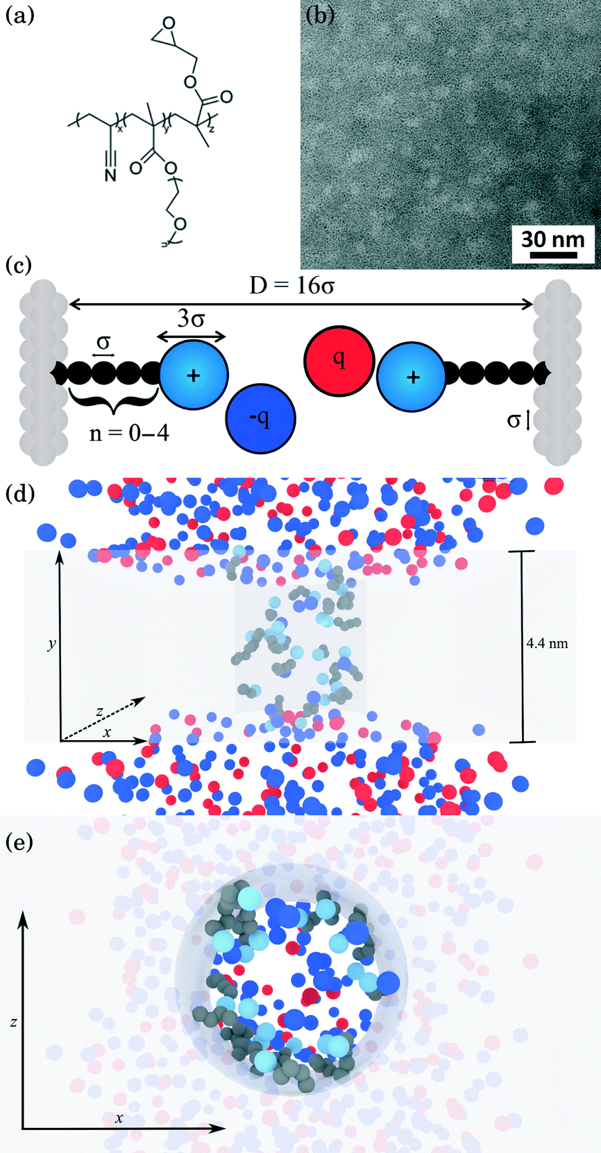
Detailed descriptions of the methodologies used to synthesize and characterize the poly(acrylonitrile-r-oligo(ethylene glycol) methyl ether methacrylate-r-glycidyl methacrylate) (P(AN-r-OEGMA-r-GMA)) copolymer [Fig. 1(a)] are provided in a prior study.27 The P(AN-r-OEGMA-r-GMA) copolymer was designed as a membrane precursor so that the mechanically robust polyacrylonitrile (PAN) material forms the rigid matrix of the membranes; the water permeable polyethylene oxide (PEO) is used to template the porous structure of the membrane; and the polyglycidyl methacrylate (PGMA) is incorporated because it allows for the facile functionalization of the membrane after fabrication. The P(AN-r-OEGMA-r-GMA) copolymer used in this study had an overall molecular weight of 250 kDa, and contained 40%, 40%, and 20% (by weight) of the PAN, POEGMA, and PGMA materials, respectively. P(AN-r-OEGMA-r-GMA) copolymer membranes were fabricated using a non-solvent induced phase separation method. The copolymer was dissolved in dimethyl sulfoxide (DMSO) at a solids concentration of 18.5% (by weight). Prior to casting, the solution was degassed overnight. To cast a P(AN-r-OEGMA-r-GMA) membrane, a 67 μm-thick layer of solution was spread on a PAN-400 (Nanostone Water, Oceanside, CA) support membrane using a doctor blade. After a 5 min evaporation period, the cast membrane was plunged into a non-solvent isopropanol bath. After soaking in the non-solvent bath for at least 10 minutes, membranes were transferred to and stored in a fresh bath of isopropanol prior to functionalization. The microphase separation of the copolymer material produces membranes that possess porous domains around 5 nm in size [Fig. 1(b)]. The micrographs in Fig. 1(b) were obtained using a FEI Titan transmission electron microscope (TEM) operating at 300 kV. Samples were prepared for TEM analysis by drop casting 5 μL of a 1% (by weight) P(AN-r-OEGMA-r-GMA) in DMSO solution onto a carbon coated copper grid. The samples were then stained using ruthenium tetroxide (RuO4) vapor for 1 h. RuO4 was produced in situ by adding excess sodium periodate to ruthenium oxide (RuO2).
 |
| | Fig. 1 Physical description of the membrane and model system. (a) Chemical structure of the P(AN-r-OEGMA-r-GMA) copolymer used to fabricate charge-functionalized membranes (b) TEM bright-field micrograph negative of the P(AN-r-OEGMA-r-GMA) membrane material. The continuous PAN that forms the matrix of the membrane appears as the dark regions and the POEGMA-PGMA material that template the charge functionalized pores appears as the light regions. Dark patches indicate inhomogeneities in the membrane thickness. (c) Coarse-grained schematic of a pore in the copolymer membrane. The side chains attached to the pore walls of the membrane represent the diamines of varying length studied here. Each dark bead in the side chain represents an ethylene repeat unit whereas the light blue sphere at the chain end was coarse grained to represent a protonated amine group. All ions are coarse-grained to represent the size of a hydrated ion. The diameter of amine end groups, free ions, and graft beads was set to 3σ, 3σ, and σ respectively, where σ = 0.256 nm. The diameter of the pore was set to 16σ. (d, e) Snapshots of a simulation from system 1 (see text for description) with spacer length n = 10 (note the n in (c) refers to number of beads not spacer length n), ρgraft = 20 grafts in the pore and MgCl2 concentration of ∼160 mM. The space occupied by the membrane atoms is greyed out in order to depict the structure of the pore more clearly. Red and blue spheres represent cations and anions, respectively, light blue spheres represent the amine end groups, and dark spheres represent the carbon groups in the spacer arm backbone. In (d), all atoms are shown from a side-on perspective, while (e) presents a top-down perspective of the membrane with ions in front of the membrane removed for clarity. | |
Charge functionalized membranes were generated by reacting a P(AN-r-OEGMA-r-GMA) membrane in an aqueous solution containing a dissolved diamine. The nucleophilic ring-opening of the epoxide moieties in the PGMA by the diamine allowed for the covalent attachment of one end group onto the pore walls of the membrane. The other end group extended into the center of the pore and imparted a positive charge to the membrane. Membranes with diamine spacer arm lengths (defined as the number of carbon atoms between the amine end groups) of n = 2, 3, 6, 8 were prepared by soaking epoxy-functionalized membranes in 2 M 1,2-diaminoethane, 1,3-diaminopropane, 1,6-diaminohexane, 1,8-diaminooctane solutions, respectively, at room temperature for 3 h. To produce a membrane functionalized with a diamine spacer arm length of n = 10, 1,10-diaminodecane was dissolved in water at 65 °C. Subsequently, an epoxy-functionalized membrane was immersed in the 2 M diamine solution at 65 °C for 2 h. The elevated temperature was necessary to increase the solubility of the 1,10-diaminodecane. Jeffamine side chains were grafted to the pore walls by submerging an epoxy-functionalized membrane in a mixture of 40 mL Jeffamine ED600 (Huntsman, The Woodlands, TX) and 40 mL DI water at 60 °C for 8 h. After each reaction, the membranes were rinsed with and stored in DI water.
2.2 Molecular dynamics simulation-coarse grained membrane system
Functionalized copolymer membranes are complex systems involving thousands of atoms that span micrometer length scales. In order to capture the molecular selectivity, a fully atomistic model would appear to be an ideal representation. However, for molecular dynamics simulations at atomic resolution, we may expect—at best—to obtain timescale resolution of the membrane dynamics on the order of a few microseconds, even with the significant speed of modern hardware.34 Considering that charge-selective membranes frequently achieve rejection rates of 90% or higher,27,35 only a few ions can be expected to complete passage through the membrane on microsecond timescales, which offers insufficient statistics to understand essential properties of the rejection process. In combination these facts suggest that for molecular simulations on larger timescales that are relevant to the performance of copolymer membranes, a system must be coarse grained while retaining the salient features of the membrane pores. One must group multiple atoms together into a single unit (often also using implicit solvent) and sets the properties of the unit to resemble those of the structures that were replaced.36,37 Parameters for the coarse-grained model are determined by the application; some models are minimal and match only the properties identified as essential to the physical process. Other models invoke schemes for iterative thermodynamic optimization to match key macroscopic properties.38 In either case, the resulting model is computationally efficient, permitting exploration of larger length and time scales. One will also attempt to look at the smallest possible version of a system to maximize ergodic sampling. Such an approach is beneficial for functionalized copolymer membranes. While graft placements are necessarily discrete, an ensemble averaged pore will exhibit no granularity in their placement; further one should expect that over the full length of a membrane, there is on average no preferential placement of grafts. This suggests that a molecular simulation performed on a system with a shortened pore would provide the necessary physical details to capture membrane performance.
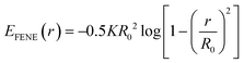
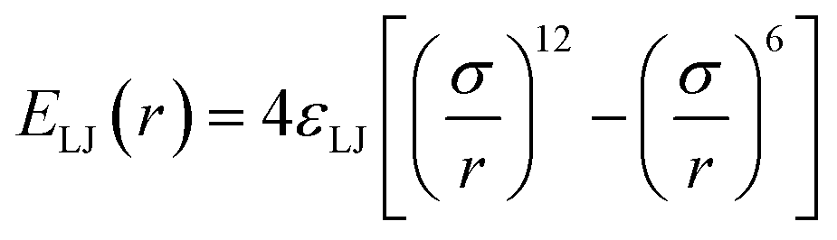
Our simulations model the porous nanostructure of the unfunctionalized copolymer membrane by using an impermeable rectangular block of stationary beads placed on an FCC lattice with a single cylindrical pore hollowed from the block by deleting the relevant beads [see Fig. 1(c)]. The scaffold beads are neutral and structural only, exhibiting simple steric repulsion. No chemical details are present that would affect ion adsorption or permit uptake through glassy regions of the membrane. Polymer grafts of different lengths representing n-alkyl-amines were attached inside the pore at randomly selected positions to achieve approximately uniform coverage of the pore interior. The repeat units of these grafts are approximated by coarse-grained beads representing ethylene repeat units, each having the length of two carbon bonds, connected by FENE springs. The last bead represents a hydrated amine terminus whose charge may be fractional to represent the ensemble average charge at a given pH. Salt ion species are coarse-grained as beads with charges, commensurate with the restricted primitive model (RPM) electrolyte.39 Our simulations use a force-field described by eqn (1), which represents the total potential energy of the system as a sum of three contributions. One is due to molecular bonds, here represented by FENE springs40 one is due to steric repulsions, and one is due to charge interactions.
| |  | (1) |
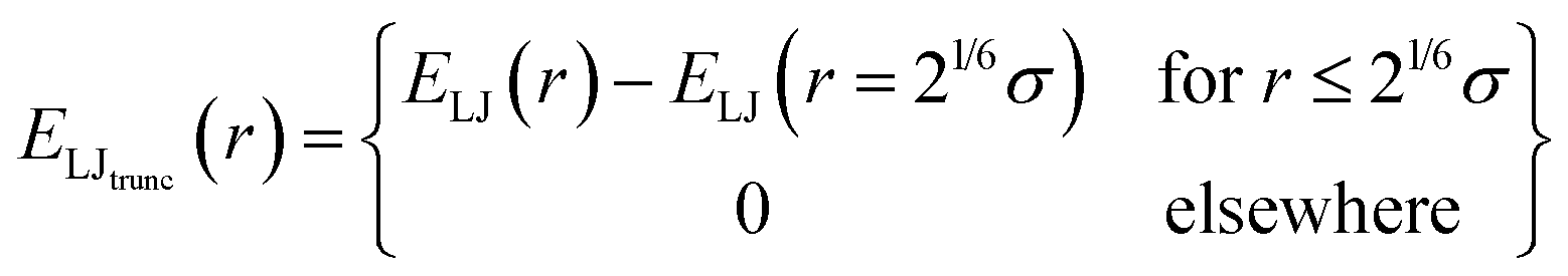
While dispersion interactions and solvation forces will play a role in the transport of solutes through the membrane, we use this minimal interaction model to first ascertain how much of the solute transport behavior may be attributed solely to the largely species-independent contributions of charge and steric repulsions. We use a ‘soft-sphere’ shifted-truncated Lennard–Jones repulsion
| | 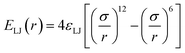 | (2) |
| | 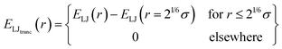 | (3) |
with the coupling constant
εLJ set by the thermal energy scale (Boltzmann's constant times temperature,
kBT). This model thus lacks specific chemical information beyond molecular size and charge. While the scaffold beads that constitute the matrix of the membrane are subject to a holonomic constraint, the connectivity of the molecular grafts is modeled by FENE springs (
eqn (4)).
| |  | (4) |
Here,
R0 is the maximum extent of the FENE bond,
K is a spring-strength constant. To represent the various alkyl-diamines, we set the size of all uncharged beads (both neutral wall and graft beads) by the length associated with two carbon–carbon single bonds,
σ = 0.256 nm.
41 No angles or torsions are defined, thus these chains are more flexible than the amine salts used in experiment.
Charged species (end groups and free ions) are modeled using the hydrated ion radius, which is reasonably approximated by 3σ for a large variety of mono- and di-valent ionic species.42 FENE bonds characterized by a spring constant  and a maximal length R0 = 2σ were utilized for simulations. Beads which are bonded also experienced the shifted-truncated Lennard-Jones interaction with constant
  and diameter set to the arithmetic mean of the two bonded species (σ or 2σ for ethylene–ethylene and ethylene–amine bonds, respectively). In addition to free salt species, used in the rejection experiments, additional monovalent ions were added to neutralize the charges within the membrane pores.
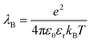
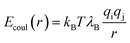
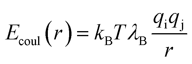
The energy scale for electrostatic interactions in the aqueous medium was matched using the Bjerrum length, λB, which is equal to 7.18 Angstroms in water at 300 K.42 This length encodes the distance at which monovalent charges have an interaction strength equal to thermal energy.
| |
| (5) |
where e is the elementary charge,
kBT is the thermal energy scale, Boltzmann's constant times temperature, and
εr is the dielectric constant. To account for the dielectric and viscous properties of the medium we utilized an implicit solvent, which is held at constant temperature of 300 K
via a Langevin thermostat and whose dielectric constant matches that of water
εr = 77.7.
43 In terms of simulated units, the resulting Bjerrum length is 2.8
σ.
41 The resulting Coulombic repulsion is given by
| |  | (6) |
where
qi and
qj are the charges on atoms +2, +1, and −1 for Mg
2+, NH
3+ and Cl
− respectively. The long-range forces in
eqn 6 are handled by the particle–particle—particle–mesh method
44 using the cutoff parameter of 5
σ and setting the dimensionless accuracy in the calculated electrostatic forces as 10
−5.
According to our identification of σ with the carbon backbone of the spacer arms, the diameter of the pore was set to 16σ commensurate with a 4 nm pore size.27 The density of grafts inside the pore ρgraft is defined as the grafts per pore with units of grafts nm−3. Typical configurations, displaying both ions and grafts (with the membrane atoms represented by a transparent shaded volume for clarity) for side-on and top-down views are given in Fig. 1(d) and (e).
The membrane and pore are centered at the Cartesian origin (0,0,0). We utilized two different sizes of simulation box with the dimensional ratios 1![[thin space (1/6-em)]](https://www.rsc.org/images/entities/char_2009.gif) :2:1. A larger box, 12.86 nm × 25.73 nm × 12.86 nm was used in initial studies, while a smaller volume 6.43 nm × 12.86 nm × 6.43 nm was used for extensive statistical data gathering. We explicitly verified that the size of box does not quantitatively affect our results. Still, we label results from system 1 and system 2 where each is used in our study. The coarse grained membrane used in the simulations was of dimensions 12.86 nm × 4.4 nm × 12.86 nm and 6.43 nm × 4.4 nm × 6.43 nm in system 1 and system 2 respectively. All boundaries are periodic. The temperature was held at 300 K via Langevin dynamics.45
:2:1. A larger box, 12.86 nm × 25.73 nm × 12.86 nm was used in initial studies, while a smaller volume 6.43 nm × 12.86 nm × 6.43 nm was used for extensive statistical data gathering. We explicitly verified that the size of box does not quantitatively affect our results. Still, we label results from system 1 and system 2 where each is used in our study. The coarse grained membrane used in the simulations was of dimensions 12.86 nm × 4.4 nm × 12.86 nm and 6.43 nm × 4.4 nm × 6.43 nm in system 1 and system 2 respectively. All boundaries are periodic. The temperature was held at 300 K via Langevin dynamics.45
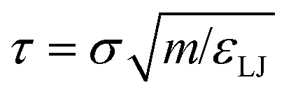
All simulations were run in the LAMMPS parallel molecular dynamics package.46 The mass of all species, in reduced units, was set to 1. The timestep length was δt = 0.005τ in reduced units, where  . This may be translated into real time and length scales using
 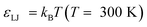 , σ = 0.256 nm and m = 28 amu (corresponding to molecular weight of ethylene), resulting in δt = 4.183 femtoseconds. Unless otherwise specified both systems were equilibrated for 1500τ (1.254 nanoseconds). After this, statistics were collected over a 4500τ (3.764 nanoseconds) for system 1 and 5500τ (4.601 nanoseconds) for system 2.
2.3 Solute rejection relates to effective membrane porosity
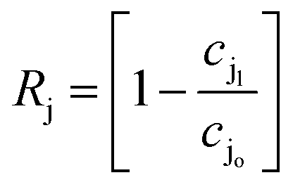
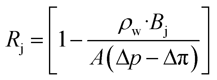
In desalination and filtration applications, a key property of interest is the fraction of a particular species (here, j) rejected by the membrane. This is calculated experimentally using the ratio of the solute concentration in the effluent to that in the feed solution, and may be expressed as,47| |  | (7) |
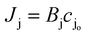
where cjl and cjo is concentration of ionic species j leaving the downstream effluent side of the membrane and entering the feed side of the membrane, respectively. Assuming a dilute solution and a membrane that rejects solute effectively (i.e., cjl ≪ cjo), the molar salt flux, Jj, through the membrane is expressed as,| |  | (8) |
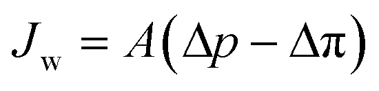
where Bj is the salt permeability constant. The mass flux Jw of water through the membrane can be written as| | 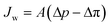 | (9) |
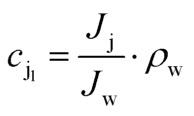
where Δp is the applied pressure that drives permeation, Δπ is the osmotic pressure across the membranes, and A is the hydraulic permeability. The hydraulic permeability is an intrinsic constant for a given membrane that encompasses the particular properties of solvent permeation through a given channel.48 A classical fluid dynamics analog is the geometric constants in pressure-driven Hagen–Poiseuille flow. Assuming a well-mixed effluent, cjl can be expressed as| |  | (10) |
where ρw is the density of the water and thus, we obtain the relevant definition for the fraction of ionic species rejected.47| | 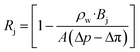 | (11) |
We note that in eqn (11), there are three types of terms—adjustable experimental parameters (ρw, Δp, Δπ), a flow-specific parameter determined by the geometry of the membrane (A), and a term defined by the interactions between the solute and the membrane (Bj). We aim to characterize this last term for charge functionalized membranes, as for pores with a given aperture, we posit only Bj will be affected by functionalization. This simplifying assumption is expected to hold for low to moderate pressure conditions and salt concentrations. Importantly, we can connect it directly to the porosity of the membrane in the limit of an un-functionalized membrane, suggesting that an effective porosity may be defined through molecular interactions that can characterize the filtration behavior of the system.
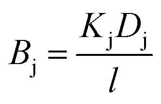
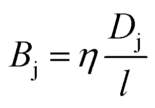
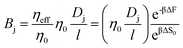
We first break the permeability constant down into standard parameters for the solution-diffusion model of transport,47 separating the solute diffusivity (D) in the membrane from the solute partition coefficient (K), and including a fundamental diffusive length scale l.
| |  | (12) |
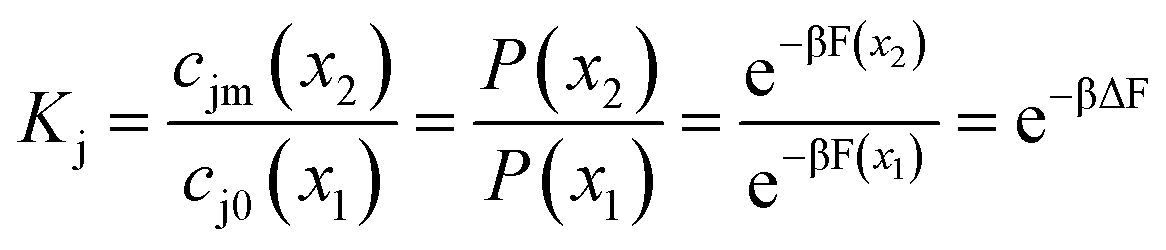
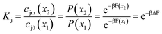
The salt partition coefficient can be calculated if one knows the concentration of salt on both sides of the feed interface. If we assume that the pores are featureless, and the solvent is ideal, equating the chemical potentials on each side of the interface relates these concentrations to the Boltzmann probability for an ion to reside inside or outside a membrane pore,
| |  | (13) |
where
x2 and
x1 denote the locations inside and outside a uniform pore, respectively,
β = 1/
kBT, and
F is the Helmholtz free energy.
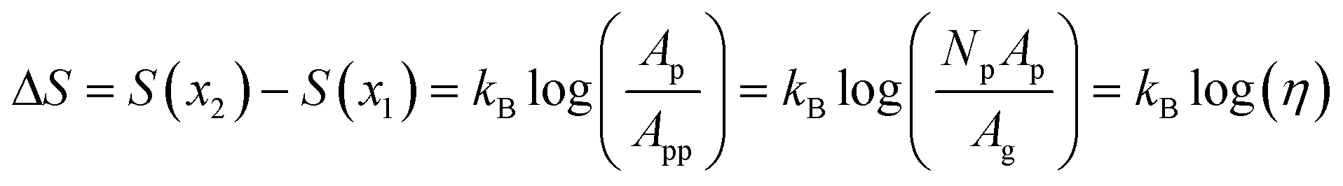
We can infer valuable information about our membranes by considering the case of a prototypical “molecular sieve”, where selection is purely entropic (ΔF = ΔU – TΔS = −TΔS). In our experimental system of interest, this would correspond to the limit of an unfunctionalized membrane. Here, a connection may be established between the membrane porosity η, defined as the ratio of pore area to membrane area, and the free energy barrier ΔF experienced by solutes traversing the membrane. In the ideal limit, the entropy difference between the two locations, x2 and x1 , is related to the ratio of local free volumes; for a small length Δx, this becomes the ratio of the accessible membrane cross-sectional area to the average area associated with a single pore.
| |  | (14) |
where
Ap is the cross-sectional area of a single pore and the per-pore area
App =
Ag/
Np is the projected geometrical area of the membrane
Ag divided by the total number of pores
Np. Importantly, through
eqn (12)–(14), this relates the membrane porosity directly to the salt permeability constant.
| |  | (15) |
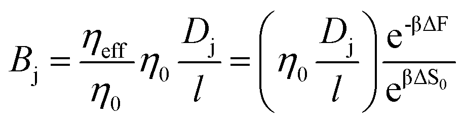
Note that we have neglected all interactions that depend on the size or chemistry of the solute; it is essentially an ideal gas. We can extend this intuition to the more general situation by appealing to an effective porosity, defined through the relative free energies of ions inside and outside the membrane pores. The perspective is useful, in that it intuitively implies a hierarchical narrowing of membrane pores after functionalization with charged moieties, and yields a direct relationship for the lower bound “molecular sieve” performance of a given membrane. Importantly,
| |  | (16) |
where the subscript 0 refers to the molecular-sieve limit of the un-functionalized membrane. This suggests that we may compute the performance of an arbitrary membrane by computing the entropy change entering an analogous bare membrane and calibrating to experimental values for the same. We adopt this method in the following section, utilizing the computation of free energy in a bare pore, which is dominated by the entropy associated with ion entry into the pore, to calibrate the permeability for cases where the membrane is functionalized with diamine salts of varying length. Practically, then, we may compute the transport through such membranes by combining
eqn (11) with
eqn (12) and
(13) the solute rejection can be rewritten as
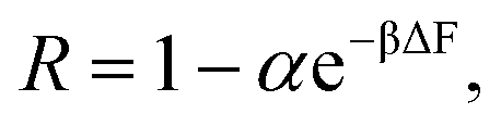
| |  | (17) |
with
α a prefactor representing the grouped constants from
eqn (11) and
(12). Therefore,
eqn (17) provides a way to calculate the rejection values of dissolved ionic species from the free energy barrier for ion entry obtained from the MD simulation.
3. MgCl2 rejection experiments, simulations, and comparison
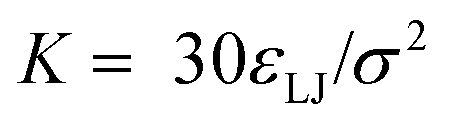
The protocol for measuring ion rejection experimentally follows the methodologies detailed in prior literature.27 Briefly, a 1-in diameter sample of membrane was punched out using a circular hole punch, and placed in a 10 mL Amicon 8010 stirred cell (Millipore). 10 mL of a MgCl2 aqueous solution at a prescribed concentration was then poured into the stirred cell. The MgCl2 solution was filtered through the membrane at an applied pressure of 50 psig while stirring the solution at 600 rpm. The feed solution was stirred vigorously to reduce the effects of concentration polarization.49 1 mL samples of the solutions that permeated through the membrane were collected in clean glass vials. In some experiments, solute rejection was tested as a function of pH using the same stirred cell system. Hydrochloric acid or sodium hydroxide solutions were added to adjust the pH of the feed solutions down or up, respectively. An Accumet AP115 portable pH meter (Fisher Scientific, Waltham, MA) was used to measure pH values. In all experiments, a 1 mL sample of the feed solution was collected. MgCl2 retention was determined by measuring the concentration of Mg2+ in the effluent and feed solution samples using a Perkin Elmer Optima 8000 Inductively Coupled Plasma Optically Emitting Spectra (ICP-OES). Eqn (7) was then used to calculate the retention ratio.
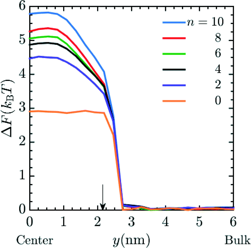
Unless otherwise noted, simulations were performed in system 1 with 400 magnesium and 800 + qNg chloride ions and in system 2 with 43 magnesium and 86 + qNg chloride ions where q is the charge on the amine, and Ng is the number of total amine grafts. The resulting ionic strength is 480 mM. As defined in the model section above, the bare, unfunctionalized membrane corresponds to n = 0 graft length, and addition of 1,2-diaminoethane adds two carbons (for n = 2) as does every spacer arm thereafter (n = 4, 6, 8 and 10). The graft density for the simulations was set at ρgraft = 20 grafts per pore (∼0.4 grafts nm−3), which is comparable to the experimental conditions.27 Potential of mean force (PMF) calculations, were performed for the insertion of Mg2+ ions into the pore. These calculations were performed using a combination of umbrella sampling50 and the Weighted Histogram Analysis Method (WHAM).51,52 An umbrella spring constant of 50 εLJ/σ2 was utilized to constrain sampling of the y-coordinate for a single magnesium ion, which characterizes the extent of transport into the membrane pores [the x and z coordinates sample freely]. A total of 90 windows were utilized, with this value chosen to optimize overlapping statistics and yield a smooth PMF. After a configuration is made, the system is allowed to equilibrate before gathering statistics on the position of the chosen ion. The WHAM algorithm was applied in post-processing using the software OPT-MHM.52 The plotted free energies are calculated from an average over three independent configurations of the grafts within a pore to reduce the degree of selection bias and to produce values that better represent the free energy values in the experimental system. The results are presented in Fig. 2 and indicate that the greatest free energy barrier for entry of Mg2+ into the pore corresponds to the longest spacer arm length while the PMF values obtained from an un-functionalized membrane (labeled as ‘n = 0’) exhibit the lowest barrier. Between these two values, a monotonic increase in the size of the barrier is observed with increasing chain lengths. The reasons for this are twofold: longer chains imply more excluded volume within the pore and concomitantly push the terminal charges toward the center of the pore, increasing the repulsive coverage of the amine group. These PMFs are quite smooth; in Fig. 3 we plot the bootstrapped error50,53 associated with the n = 4 PMF;52 this estimated at less than ∼3% of the magnitude of the PMF barrier. This is indicative of the error expected in the free energy value at the center of the pore obtained from the simulation data.
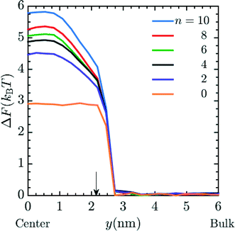 |
| | Fig. 2 PMF profile for the entry of a Mg2+ ion into the pore of a membrane when I ∼ 480 mM MgCl2 salt is present in the system, where I represents the ionic strength. Each line represents the free energy barrier for the entry of a Mg2+ ion into the pore. The final free energy profile calculated was the average of 3 different cases of graft placements inside the pore. These simulations were done in system 1. The orange line represents a bare (unfunctionalized) membrane, n = 0. The other lines correspond to functionalized membranes with increasing spacer length labeled in the legend. Here, y = 0 nm and y = 6 nm corresponds to the membrane pore center and the bulk phase, respectively. The arrow shows the interface between the membrane and the bulk solution. The ρgraft in the membrane for the simulation was 20 grafts per pore. | |
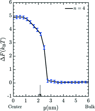 |
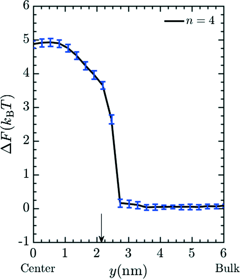
| | Fig. 3 Typical error in PMF values (see Fig. 2) obtained via bootstrap resampling for the n = 4 spacer. | |
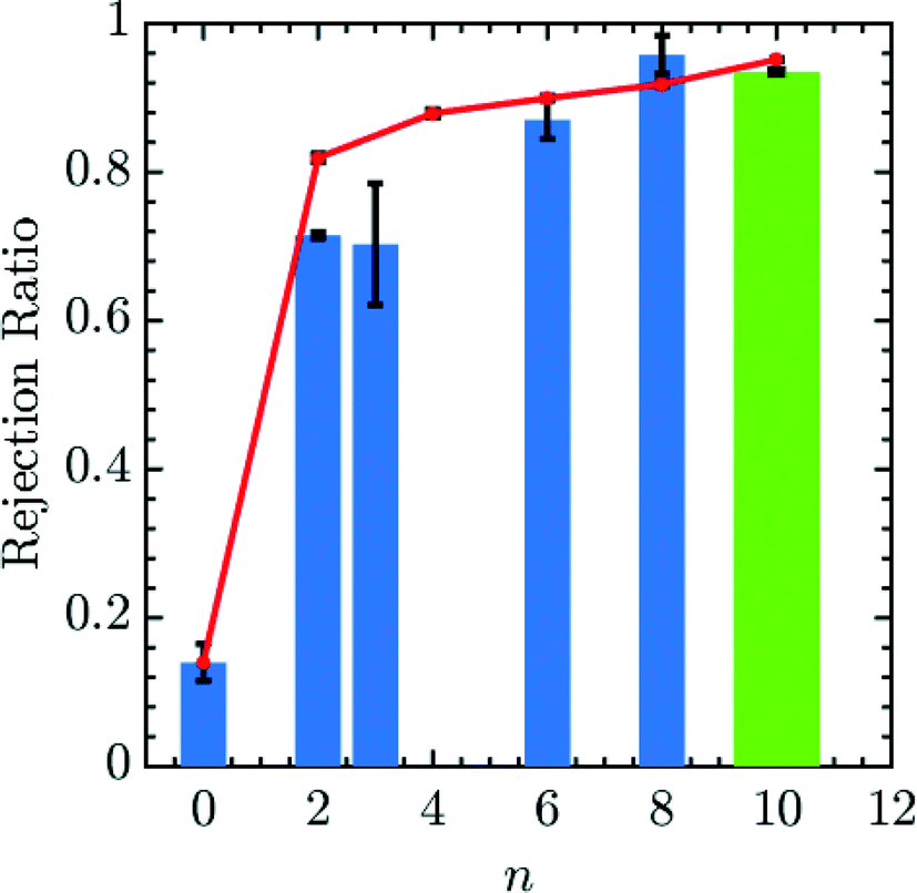
Fig. 4 demonstrates that the rejection of Mg2+ ions increases with increments in the number of spacers in the grafted amines. PMF values at the center of the pore may be translated to a value for the fraction of ions rejected using eqn (16) and (17). We first calibrate a bare membrane simulation data to the bare membrane experimental data to obtain the prefactor α in eqn (17). Subsequently, the rejection values of Mg2+ for increasing spacer-arm lengths, n, is calculated by comparing ΔF to this reference state. The comparison between the calculated rejection ratio values and the experimental values27 for the Mg2+ ion is presented in given in Fig. 4. Even though the experimental data was obtained under flow conditions imposed by an applied pressure of 50 psi,27 and the simulation model does not include hydrodynamic effects, the PMF values from simulations are able to predict the experimental rejection values of Mg2+ with good accuracy. This is in part due to the fact that hydrodynamic effects enter eqn (17) only through the calibration factor α. However, it still indicates that rejection of ionic species under moderate flow conditions is largely dependent upon equilibrium thermodynamics resulting from interaction between the ionic solutes and the membrane, which is reflected in the free energy profile for the entry of Mg2+ ion into the pore. In particular, the improved Mg2+ rejection, at a constant pore size, results because the spacer acts to spread the charge away from the pore walls and toward the center of the pore, effectively reducing the membrane porosity. The simulation result obtained with n = 10 is compared in Fig. 4 with experimental data for membranes functionalized with Jeffamine D600 polyetheramine (∼600 gram per mole).54 The different chemistry is necessitated to solubilize the amine salts, which leads to problems in membrane functionalization at and above n = 10. Though the molecular weight of Jeffamine D600 is higher than the molecular weight of the 1,10-diaminodecane (∼172 gram per mole) which would be used to generate functionalized membrane with spacer length n = 10, we should expect the increased solubility to yield comparable grafting densities to the large n limit of 1,n diaminoalkanes. The increased flexibility of the longer Jeffamine appears to be represented quite well by our model.
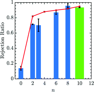 |
| | Fig. 4 Simulated and experimental rejection ratio for Mg2+ plotted as a function of spacer arm length (n). The prefactor α is obtained by calibrating with the bare membrane n = 0. Simulation results (red lines) are able to qualitatively and quantitatively predict membrane performance with variable spacer arm length. The bar lines, representing experimental data, are listed according to the spacer arm length between the free amine end groups and the wall-binding site. n equal to 0, 2, 3, 6 and 8 (blue bar lines) are for membranes functionalized with standard diamine salts, while the green bar line is obtained from membranes functionalized with Jeffamine D600. Experimental rejection ratios were determined by comparing the concentration of Mg2+, measured by ICP-OES, in the solution that permeated through a membrane to that in a 10 mM MgCl2 feed solution. An applied pressure of 50 psi was used in the experiments. | |
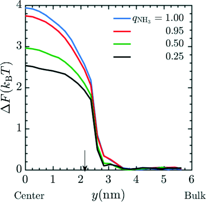
Next, we attempt to capture the effects of partial charging on membrane performance; this allows us to predict the performance of a membrane under variable pH conditions. We again calculated the insertion energy of Mg2+ at a fixed spacer arm length (n = 6) and graft density of 20 grafts per pore, here using fractional charges to represent the ensemble-average charge, chosen to be consistent with the fraction of amine moieties protonated at various values of the pH. The simulations were performed in system 2 with qNH3 = (1.00, 0.95, 0.5, 0.25). The conditions for umbrella sampling were the same as used to produce Fig. 2. The plotted free energies are calculated from an average over three independent configurations of the grafts within a pore. PMF curves are given in Fig. 5 and indicate that the ΔF decreases as the fractional charge decreases, which is consistent with the reduced electrostatic interactions between the positively-charged Mg2+ and the membrane pore.
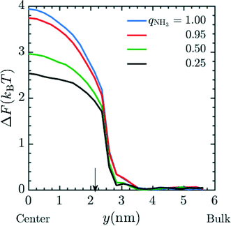 |
| | Fig. 5 PMF profile for the entry of Mg2+ into a pore with fractional charge on amine beads (qNH3) when MgCl2 is present as the salt in the system. The final free energy profile calculated was the average of 3 different cases of graft placement inside the pore. These simulations were done in system 2. In the simulation, the ρgraft in the pore was set to 20 grafts per pore and n = 4. Amines were given fractional charges to represent the ensemble average charge at different values of pH. The result indicates an increase in the free energy barrier corresponding to a decrease in the pH of the environment. Here, y = 0 nm and y = 6 nm corresponds to the membrane pore center and the bulk phase, respectively. The arrow corresponds to the interface between the membrane and the bulk solution. | |
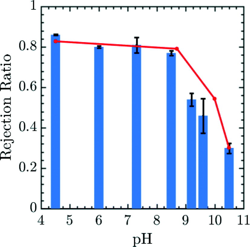
The results may be correlated to experimental data using the Henderson–Hasselbalch equation to relate pH and q.55 The prefactor α was obtained in this case by calibrating the 0.25 amine charge data to the pH 10.5 experimental data27 and rejection ratio values for different pH was obtained from simulations using the pore center PMF values in conjunction with eqn (17). The comparison of experimental rejection values with simulation rejection values is given in Fig. 6. The experimental data in Fig. 6 demonstrate that using charge-functionalized membranes the rejection of the ionic species can be tuned by altering the pH of the surrounding environment. Despite its simplicity, our coarse grained model predicts variations in the rejection ratio impressively under variable pH conditions.
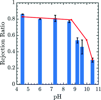 |
| | Fig. 6 Simulated (red lines) and experimental rejection ratio (blue bar lines) for Mg2+ plotted as a function of pH. α is obtained by calibrating 0.25 amine charge simulation data to the pH 10.5 experimental data.27 The error bars correspond to experimental data. The diamine spacer length was n = 6 in both simulation and experiment corresponding to membrane generated by soaking epoxy-functionalized membrane in a 1,6-diaminohexane solution. This comparison in particular suggests a high degree of robustness for the model presented in the paper. Experimental rejection ratios were measured for a 10 mM MgCl2 solution over a pH range from 2.5 to 10.5. The pH of the feed solution was adjusted by adding HCl and NaOH as needed. The Mg2+ concentration in permeate and feed solutions were measured by ICP-OES. | |
It should be noted that the experimental and simulation results that are compared in Fig. 4 and 6 are in quite good agreement with no empirical fitting parameters, and no attempt to match the experimental system beyond length and charge energy scales, suggesting an impressive level of robustness and predictive capabilities in this model. Hence, our model can offer expectations for the rejection of ionic species under different conditions, which can be leveraged to design membranes in silico before undertaking time consuming batteries of experiments. Modeling and optimizing the membrane system with current continuum models would be difficult as the thermodynamics arising from the interactions between the solutes and the membrane would not be accurately accounted for as the spacer arm length was varied, which, as indicated by the comparison results, plays major role in the transport of the dissolved solutes. As such, the use of MD simulations provides a way to capture these interactions accurately and efficiently. In the case of the charge-functionalized membranes examined here, the simulations provide information on how to control ion rejection through careful selection of the spacer arm length. In future efforts, having such an efficient MD model is an indispensable tool for furthering membrane design, as it is able to include essential molecular-scale information that continuum models currently in use cannot be easily modified to account for.
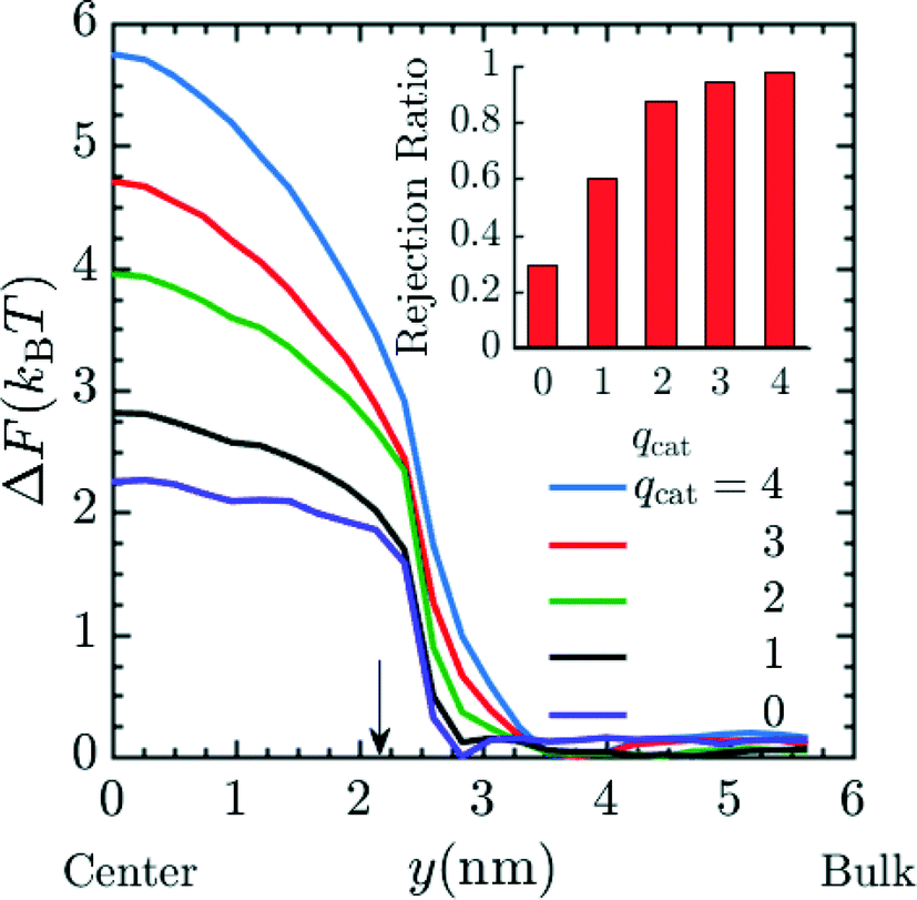
So far we have only investigated the variation of spacer length and pH on the rejection of the Mg2+, but it is possible that ionic species of different valence could be present in the contaminated water or one would like to preferentially reject ions of higher valence, as is done for K+ and Na+ relative to Mg2+ and Ca2+ in conventional water-softening technology.56,57 Hence, we performed additional simulations in order to predict the rejection of ionic species of different valence by these functionalized membranes. The results presented in Fig. 7 utilize system 2 with 20 grafts per pore, and n = 4. The number of cations present in the system in order of increasing qcat from 1 to 4 were 86, 43, 29 and 22 respectively along with their corresponding counter ions of charge −1e. For the case of qcat = 0, a total of 172 neutral beads representing neutral solute were present in the system corresponding to total number of solute particles (cations + anions) in qcat = 1 simulations. The diameter of neutral solutes in the simulation was 3σ such that the steric interaction in qcat = 1 and the qcat = 0 simulations were similar and the simulations differed in electrostatic interaction only. Fig. 7 depicts an increase in the free energy barrier (suggested by PMF values at y = 0 nm) for the entry of the cation as the qcat increases. The result indicates that the probability for the rejection of cation increases with higher charge as suggested by eqn (17). This rejection probability can be quantified in terms of rejection ratio values by calibrating the qcat = 2 simulation data with n = 6 experimental data presented in Fig. 4, to obtain α and then rest of the rejection values for varying qcat was calculated using eqn (17). The rejection ratio values for varying qcat are presented as red bar plot in the inset of Fig. 7, which suggests higher rejection with higher cationic charge. Our simulation results in Fig. 7 predict that higher-valence metal ions are rejected far more readily; importantly, the predicted rejection of between monovalent and divalent ions closely matches our recent experiments, with a predicted rejection of approximately 60% for monovalent cations and 90% for divalent cations (cf.Fig. 4 of ref. 27). We would like to mention here that although we did not perform simulations for different chemical species with the same valence number, such as K+ and Na+, such simulations could be performed with the current model by introducing appropriate van der Waals parameters for each ion.58,59 We expect that with such minor modification, good rejection estimates for K+ and Na+ or other ions with similar valence but different chemical identity could be produced.
 |
| | Fig. 7 PMF profile for entry of cation with increasing charge (qcat) into the pore, suggestive of higher free energy barrier for cations with higher charge and hence increased rejection due to lower Boltzmann probability of the cation to reside inside the pore. The number of cations present in the system in order of increasing qcat from 1 to 4 were 86, 43, 29 and 22 respectively along with their corresponding coarse grained counter ions of charge −1e. For the case of qcat = 0, a total of 172 neutral beads representing neutral solute were present in the system. The graft density and spacer length (n) in the simulation were 20 grafts per pore and 4 respectively. Here, y = 0 nm and y = 6 nm corresponds to the membrane pore center and the bulk solution, respectively. The arrow corresponds to the interface between the membrane and the bulk solution. The inset plot provides the expected rejection values obtained from the free energy values at the center of the pore. The qcat = 2 data was calibrated with n = 6 experimental data from Fig. 4 to obtain α and rest of the rejection values were obtained by using eqn (17). | |
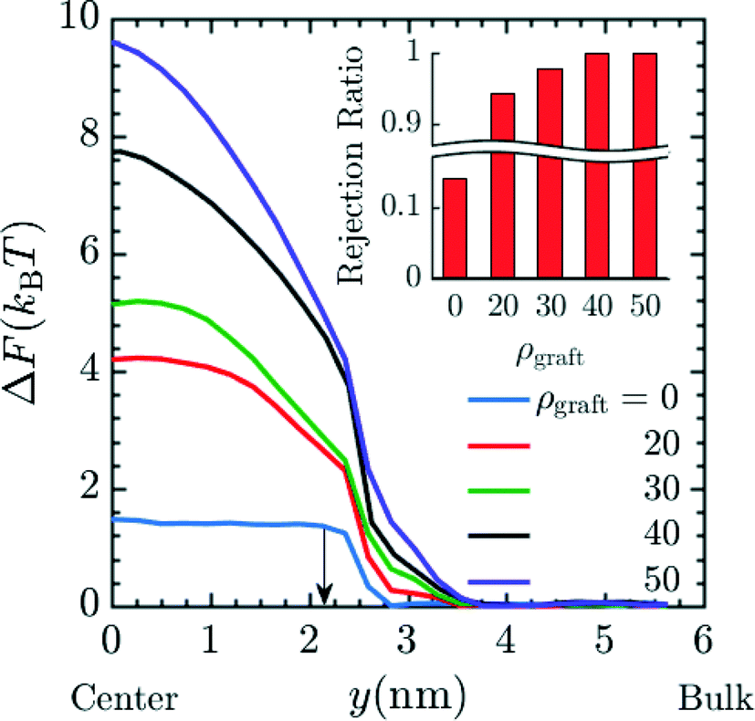
Finally, we investigated varying the number of grafts inside a pore. Such variations could be realized by increasing the PGMA content of the membrane, which can be accomplished by rational design of the precursor copolymer composition. The results in Fig. 8 correspond to simulations with n = 4 in system 2 for insertion of Mg2+ into the pore. These results suggest that the free energy barrier increases and that the charged species will be rejected to greater extents as the number of grafts inside the pore is increased. This can be attributed to the reduction in effective membrane porosity from the concomitant increases in steric repulsion and electrostatic force from protonated amines. This combined effect leads to ionic species being strongly rejected. The rejection ratio values expected when the number of grafts inside the pore is increased can be calculated by calibrating the ρgraft = 0 simulation data in Fig. 8 with the bare membrane (n = 0) experimental data (Fig. 4) to obtain α. The resulting rejection ratios are presented in the inset of in Fig. 8. The rejection ratio of a bare membrane compared to that of a membrane with 20 grafts per pore (∼0.4 grafts nm−3) suggests that introducing charged moieties along the pore wall leads to the most significant increase in the rejection ratio. Comparing the relative change in the rejection ratio going from 20 grafts per pore to 30 grafts per pore (∼0.5 grafts nm−3), 30 grafts per pore to 40 grafts per pore (∼0.7 grafts nm−3), and 40 grafts per pore to 50 grafts per pore (∼0.9 grafts nm−3) demonstrates that increases in graft density beyond a range of 30–40 grafts per pore or ∼0.5–0.7 grafts nm−3 leads to diminishing returns in terms of rejection values, which suggests that this range is sufficient for optimal performance.
 |
| | Fig. 8 Effect of increasing the graft density i.e. grafts per pore (ρgraft) on the free energy barrier for entry of Mg2+ into the pore again signifying lower probability of the Mg2+ to reside inside the pore, hence suggestive of higher rejection of Mg2+ with increasing graft density. The increase in graft density represents increase in number of grafts per pore ranging from 0 grafts per pore/bare membrane to 50 grafts per pore or ∼0.9 grafts nm−3. The carbon length n was set to 4 in the simulation. This result also indicates that increase in graft density has strong positive effect on the free energy barrier for the entry of Mg2+ with the value going up to 10 kBT in the case of ρgraft = 50. Here, y = 0 nm and y = 6 nm corresponds to the membrane pore center and the bulk solution, respectively. The arrow corresponds to the interface between the membrane and the bulk solution. The inset plot provides the expected rejection values obtained from the free energy values at the center of the pore. The ρgraft = 0 data was calibrated with n = 0 experimental data from Fig. 4 to obtain α and rest of the rejection values were obtained by using eqn (17). | |
Summary
Here, we have presented a MD model capturing the essential equilibrium thermodynamics of the salt rejection process. The experimental results show that by altering the spacer arm length of the grafted amine functionality the rejection of ionic species in these membranes may be optimized. Using an effective membrane porosity, which results from changes in the free energy barrier due to variation in the spacer arm length or local pH conditions, our model is able to predict the rejection of ionic species. Calibration of a single parameter with the experimental data that accounts for the average internal membrane structure and pressure differentials, yielded exceptional agreement between model predictions and experimental data. This suggests impressive predictive capabilities in our MD model, which can be utilized to design membranes in silico by accounting for information that cannot be accurately represented in current continuum models. We subsequently applied our model to make further predictions involving variable graft numbers and charge valence.
The results are highly encouraging; improvements to the model should be expected given less coarse estimates for the grafting density, incorporation of more explicit solvation effects, and explicit accounting of pH-mediated surface charges. The model we have developed presents a good starting point for examining the vast phase space available for membrane optimization that is too time consuming to address experimentally. A completed membrane model would have the capabilities to help researchers develop membranes suited to many different applications where ion selective transport is critical (e.g., water filtration) and hence could be of significant use to address global water and energy issues.
Acknowledgements
VSR and JKW acknowledge computational resources at the Notre Dame Center for Research Computing (CRC). The development of free energy algorithms for this work was supported by MICCoM, as part of the Computational Materials Sciences Program funded by the U.S. Department of Energy, Office of Science, Basic Energy Sciences, Materials Sciences and Engineering Division, under grant #0J-30521-0009A. Experimental investigations in this work were made possible with support from the National Science Foundation (NSF) through the Chemical and Biological Separations Program (Award Number: 1512089), and we appreciatively acknowledge this support. WAP gratefully acknowledges support from the 3 M non-Tenured Faculty Award. We thank Hythem Sidky (Notre Dame) for technical assistance. We would like to thank the Notre Dame Integrated Imaging Facility (NDIIF) and the Center for Environmental Science and Technology (CEST) at Notre Dame; portions of this research were performed with instruments at these facilities.
References
- S. Liu and S. W. Lockless, Equilibrium Selectivity Alone Does Not Create K+-Selective Ion Conduction in K+ Channels, Nat. Commun., 2013, 4, 2746 Search PubMed.
- M. Y. Kariduraganavar, R. K. Nagarale, A. A. Kittur and S. S. Kulkarni, Ion-Exchange Membranes: Preparative Methods for Electrodialysis and Fuel Cell Applications, Desalination, 2006, 197(1–3), 225–246 CrossRef CAS.
- C. Cao, W. Liu, L. Tan, X. Liao and L. Li, Sodium-Ion Batteries Using Ion Exchange Membranes as Electrolytes and Separators, Chem. Commun., 2013, 49(100), 11740–11742 RSC.
- G. M. Geise, M. A. Hickner and B. E. Logan, Ammonium Bicarbonate Transport in Anion Exchange Membranes for Salinity Gradient Energy, ACS Macro Lett., 2013, 2(9), 814–817 CrossRef CAS.
- B. E. Logan and M. Elimelech, Membrane-Based Processes for Sustainable Power Generation Using Water, Nature, 2012, 488, 313–319 CrossRef CAS PubMed.
- T. Xu, Ion Exchange Membranes: State of Their Development and Perspective, J. Membr. Sci., 2005, 263(1–2), 1–29 CrossRef CAS.
- W. J. Koros, Evolving beyond the Thermal Age of Separation Processes: Membranes Can Lead the Way, AIChE J., 2004, 50(10), 2326–2334 CrossRef CAS.
- E. L. Cussler and B. K. Dutta, On Separation Efficiency, AIChE J., 2012, 58(12), 3825–3831 CrossRef CAS.
- K. Yoon, K. Kim, X. Wang, D. Fang, B. S. Hsiao and B. Chu, High Flux Ultrafiltration Membranes Based on Electrospun Nanofibrous PAN Scaffolds and Chitosan Coating, Polymer, 2006, 47(7), 2434–2441 CrossRef CAS.
- M. Elimelech and W. A. Phillip, The Future of Seawater Desalination: Energy, Technology, and the Environment, Science, 2011, 333(6043), 712–717 CrossRef CAS PubMed.
- M. Busch and W. E. Mickols, Reducing Energy Consumption in Seawater Desalination, Desalination, 2004, 165, 299–312 CrossRef CAS.
- R. Rautenbach and T. Linn, High-Pressure Reverse Osmosis and Nanofiltration, a “zero Discharge” Process Combination for the Treatment of Waste Water with Severe Fouling/scaling Potential, Desalination, 1996, 105(1–2), 63–70 CrossRef CAS.
- C. Cheng, N. White, H. Shi, M. Robson and M. L. Bruening, Cation Separations in Electrodialysis through Membranes Coated with Polyelectrolyte Multilayers, Polymer, 2014, 55(6), 1397–1403 CrossRef CAS.
- Y. Jiang and W. C. Wang, Functional Membranes Prepared by Layer-by-Layer Assembly and Its Metal Ions Adsorption Property, Polym. Adv. Technol., 2011, 22(12), 2509–2516 CrossRef CAS.
- E. Barry, S. P. McBride, H. M. Jaeger and X.-M. Lin, Ion Transport Controlled by Nanoparticle-Functionalized Membranes, Nat. Commun., 2014, 5, 5847 CrossRef CAS PubMed.
- E. A. Jackson and M. A. Hillmyer, Nanoporous Membranes Derived from Block Copolymers: From Drug Delivery to Water Filtration, ACS Nano, 2010, 4(7), 3548–3553 CrossRef CAS PubMed.
- W. A. Phillip, B. O'neill, M. Rodwogin, M. A. Hillmyer and E. L. Cussler, Self-Assembled Block Copolymer Thin Films as Water Filtration Membranes, ACS Appl. Mater. Interfaces, 2010, 2(3), 847–853 CAS.
- H. Uehara, M. Kakiage, M. Sekiya, D. Sakuma, T. Yamonobe, N. Takano, A. Barraud, E. Meurville and P. Ryser, Size-Selective Diffusion in Nanoporous but Flexible Membranes for Glucose Sensors, ACS Nano, 2009, 3(4), 924–932 CrossRef CAS PubMed.
- E. E. Nuxoll, M. A. Hillmyer, R. Wang, C. Leighton and R. A. Siegel, Composite Block Polymer-Microfabricated Silicon Nanoporous Membrane, ACS Appl. Mater. Interfaces, 2009, 1(4), 888–893 CAS.
- W. A. Phillip, M. Amendt, B. O'Neill, L. Chen, M. A. Hillmyer and E. L. Cussler, Diffusion and Flow Across Nanoporous Polydicyclopentadiene-Based Membranes, ACS Appl. Mater. Interfaces, 2009, 1(2), 472–480 CAS.
- W. Xie, H. B. Park, J. Cook, C. H. Lee, G. Byun, B. D. Freeman and J. E. McGrath, Advances in Membrane Materials: Desalination Membranes Based on Directly Copolymerized Disulfonated Poly(arylene Ether Sulfone) Random Copolymers, Water Sci. Technol., 2010, 61, 619–624 CrossRef CAS PubMed.
- Y. H. Cho, H. W. Kim, S. Y. Nam and H. B. Park, Fouling-Tolerant Polysulfone-Poly(ethylene Oxide) Random Copolymer Ultrafiltration Membranes, J. Membr. Sci., 2011, 379(1–2), 296–306 CrossRef CAS.
- C. H. Lee, B. D. McCloskey, J. Cook, O. Lane, W. Xie, B. D. Freeman, Y. M. Lee and J. E. McGrath, Disulfonated Poly(arylene Ether Sulfone) Random Copolymer Thin Film Composite Membrane Fabricated Using a Benign Solvent for Reverse Osmosis Applications, J. Membr. Sci., 2012, 389, 363–371 CrossRef CAS.
- Y. Zhang, J. L. Sargent, B. W. Boudouris and W. A. Phillip, Nanoporous Membranes Generated from Self-Assembled Block Polymer Precursors: Quo Vadis?, J. Appl. Polym. Sci., 2015, 132(21), 41683 CrossRef.
- P. Bengani, Y. Kou and A. Asatekin, Zwitterionic Copolymer Self-Assembly for Fouling Resistant, High Flux Membranes with Size-Based Small Molecule Selectivity, J. Membr. Sci., 2015, 493, 755–765 CrossRef CAS.
- A. Asatekin and C. Vannucci, Self-Assembled Polymer Nanostructures for Liquid Filtration Membranes: A Review, Nanosci. Nanotechnol. Lett., 2015, 7, 21–32 CrossRef.
- S. Qu, T. Dilenschneider and W. A. Phillip, Preparation of Chemically-Tailored Copolymer Membranes with Tunable Ion Transport Properties, ACS Appl. Mater. Interfaces, 2015, 7(35), 19746–19754 CAS.
- L. Shao, Z. X. Wang, Y. L. Zhang, Z. X. Jiang and Y. Y. Liu, A Facile Strategy to Enhance PVDF Ultrafiltration Membrane Performance via Self-Polymerized Polydopamine Followed by Hydrolysis of Ammonium Fluotitanate, J. Membr. Sci., 2014, 461, 10–21 CrossRef CAS.
- D. Rana and T. Matsuura, Surface Modifications for Antifouling Membranes, Chem. Rev., 2010, 110(4), 2448–2471 CrossRef CAS PubMed.
- A. Asatekin and A. M. Mayes, Oil Industry Wastewater Treatment with Fouling Resistant Membranes Containing Amphiphilic Comb Copolymers, Environ. Sci. Technol., 2009, 43(12), 4487–4492 CrossRef CAS PubMed.
- A. Mehta and A. L. Zydney, Effect of Spacer Arm Length on the Performance of Charge-Modified Ultrafiltration Membranes, J. Membr. Sci., 2008, 313(1–2), 304–314 CrossRef CAS.
- H. C. S. Chenette, J. R. Robinson, E. Hobley and S. M. Husson, Development of High-Productivity, Strong Cation-Exchange Adsorbers for Protein Capture by Graft Polymerization from Membranes with Different Pore Sizes, J. Membr. Sci., 2012, 423, 43–52 CrossRef PubMed.
- S. Bhattacharjee, J. Dong, Y. Ma, S. Hovde, J. H. Geiger, G. L. Baker and M. L. Bruening, Formation of High-Capacity Protein-Adsorbing Membranes through Simple Adsorption of Poly(acrylic Acid)-Containing Films at Low pH, Langmuir, 2012, 28(17), 6885–6892 CrossRef CAS PubMed.
- R. Elber, Perspective: Computer Simulations of Long Time Dynamics, J. Chem. Phys., 2016, 144(6), 060901 CrossRef PubMed.
- J. R. Werber, A. Deshmukh and M. Elimelech, The Critical Need for Increased Selectivity, Not Increased Water Permeability, for Desalination Membranes, Environ. Sci. Technol. Lett., 2016, 3(4), 112–120 CrossRef CAS.
- F. Müller-Plathe, Coarse-Graining in Polymer Simulation: From the Atomistic to the Mesoscopic Scale and Back, ChemPhysChem, 2002, 3(9), 754–769 CrossRef.
- B. Roux and T. Simonson, Implicit Solvent Models, Biophys. Chem., 1999, 78, 1–20 CrossRef CAS PubMed.
- J. C. Fogarty, S. W. Chiu, P. Kirby, E. Jakobsson and S. A. Pandit, Automated Optimization of Water–Water Interaction Parameters for a Coarse-Grained Model, J. Phys. Chem. B, 2014, 118(6), 1603–1611 CrossRef CAS PubMed.
- D. M. Heyes, Molecular Dynamics Simulations of Restricted Primitive Model 1:1 Electrolytes, Chem. Phys., 1982, 69(1–2), 155–163 CrossRef CAS.
- Q. Zhou and R. Akhavan, Cost-Effective Multi-Mode FENE Bead-Spring Models for Dilute Polymer Solutions, J. Non-Newtonian Fluid Mech., 2004, 116(2–3), 269–300 CrossRef CAS.
-
P. C. Hiemenz and T. P. Lodge, Polymer Chemistry, CRC Press, 2007 Search PubMed.
-
J. N. Israelachvili, Intermolecular and Surface Forces, 3rd edn, Academic Press, 2010 Search PubMed.
- C. G. Malmberg and A. Maryott, Dielectric Constant of Water from 00 to 1000 C, J. Res. Natl. Bur. Stand., 1956, 1, 1–8 CrossRef.
-
R. W. Hockney and J. W. Eastwood, Computer Simulation Using Particles, IOP Publishing Ltd., 1988 Search PubMed.
- B. G. de Grooth, A Simple Model for Brownian Motion Leading to the Langevin Equation, Am. J. Phys., 1999, 67(12), 1248–1252 CrossRef CAS.
- S. Plimpton, Fast Parallel Algorithms for Short-Range Molecular Dynamics, J. Comput. Phys., 1995, 117(1), 1–19 CrossRef CAS.
-
R. W. Baker, Membrane Technology and Applications, Wiley, 2012 Search PubMed.
- C. Fernández-Pineda and F. Serrano, A Study of Membrane Hydraulic Permeability Obtained by Different Procedures, J. Membr. Sci., 1984, 19(3), 325–332 CrossRef.
-
R. W. Baker, Concentration Polarization, in Membrane Technology and Applications, 2004, pp. 161–190 Search PubMed.
-
D. Frenkel and B. Smit, Understanding Molecular Simulation: From Algorithms to Applications, Academic Press, 2002 Search PubMed.
- S. Kumar, J. M. Rosenberg, D. Bouzida, R. H. Swendsen and P. A. Kollman, The Weighted Histogram Analysis Method for Free-Energy Calculations on Biomolecules. I. The Method, J. Comput. Chem., 1992, 13(8), 1011–1021 CrossRef CAS.
- T. Bereau and R. H. Swendsen, Optimized Convergence for Multiple Histogram Analysis, J. Comput. Phys., 2009, 228(17), 6119–6129 CrossRef CAS.
-
B. Efron and R. J. Tibshirani, An Introduction to the Bootstrap (Chapman & Hall/CRC Monographs on Statistics and Applied Probability), 1st edn, Chapman and Hall/CRC, 1993 Search PubMed.
- Huntsman Diamine Products, http://www.huntsman.com/performance_products/a/Products/Amines/, (accessed May 31, 2016).
- H. N. Po and N. M. Senozan, The Henderson-Hasselbalch Equation: Its History and Limitations, J. Chem. Educ., 2001, 78(11), 1499 CrossRef CAS.
- L. Llenas, X. Martinez-Llado, A. Yaroshchuk, M. Rovira and J. de Pablo, Nanofiltration as Pretreatment for Scale Prevention in Seawater Reverse Osmosis Desalination, Desalin. Water Treat., 2011, 36, 310–318 CrossRef CAS.
- S. Bequet, T. Abenoza, P. Aptel, J.-M. Espenan, J.-C. Remigy and A. Ricard, New Composite Membrane for Water Softening, Desalination, 2000, 131(1–3), 299–305 CrossRef CAS.
- K. Heinzinger, Computer Simulations of Aqueous Electrolyte Solutions, Physica B+C, 1985, 131(1–3), 196–216 CrossRef CAS.
- D. E. Smith and L. X. Dang, Computer Simulations of NaCl Association in Polarizable Water, J. Chem. Phys., 1994, 100(5), 3757 CrossRef CAS.
Footnote |
| † These authors contributed equally. |
|
| This journal is © The Royal Society of Chemistry 2016 |
Click here to see how this site uses Cookies. View our privacy policy here. 

 and a maximal length R0 = 2σ were utilized for simulations. Beads which are bonded also experienced the shifted-truncated Lennard-Jones interaction with constant
 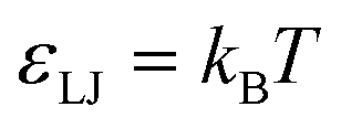 and diameter set to the arithmetic mean of the two bonded species (σ or 2σ for ethylene–ethylene and ethylene–amine bonds, respectively). In addition to free salt species, used in the rejection experiments, additional monovalent ions were added to neutralize the charges within the membrane pores.
 . This may be translated into real time and length scales using
 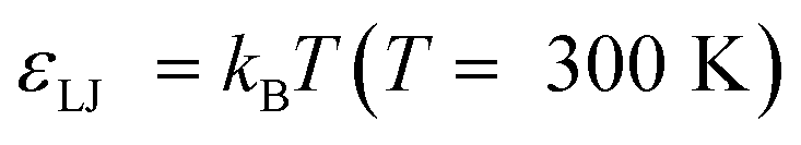 , σ = 0.256 nm and m = 28 amu (corresponding to molecular weight of ethylene), resulting in δt = 4.183 femtoseconds. Unless otherwise specified both systems were equilibrated for 1500τ (1.254 nanoseconds). After this, statistics were collected over a 4500τ (3.764 nanoseconds) for system 1 and 5500τ (4.601 nanoseconds) for system 2.