 Open Access Article
Creative Commons Attribution 3.0 Unported Licence
Dynamics of bacterial streamers induced clogging in microfluidic devices†
Mahtab
Hassanpourfard
a,
Ranajay
Ghosh
b,
Thomas
Thundat
a and
Aloke
Kumar
*c
aDepartment of Chemical and Materials Engineering, University of Alberta, Edmonton, Canada
bDepartment of Mechanical and Aerospace Engineering, University of Central Florida, FL 32816, USA
cDepartment of Mechanical Engineering, University of Alberta, Edmonton, Canada. E-mail: aloke.kumar@ualberta.ca
First published on 19th September 2016
Abstract
Using a microfabricated porous media mimic platform, we investigated the clogging dynamics of bacterial biomass that accumulated in the device due to the formation of bacterial streamers. Particularly, we found the existence of a distinct clogging front which advanced via pronounced ‘stick-slip’ of the viscoelastic bacterial biomass over the solid surface of the micro pillar. Thus, the streamer, the solid surface, and the background fluidic media defined a clear three-phase front influencing these advancing dynamics. Interestingly, we also found that once the clogging became substantial, contrary to a static homogenous saturation state, the clogged mimic exhibited an instability phenomena marked by localized streamer breakage and failure leading to extended water channels throughout the mimic. These findings have implications for design and fabrication of biomedical devices and membrane-type systems such as porous balloon catheters, porous stents and filtration membranes prone to bacteria induced clogging as well as understanding bacterial growth and proliferation in natural porous media such as soil and rocks.
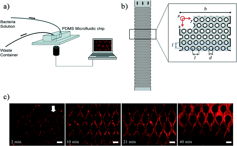
Bacterial streamers, which are microscopically slender filamentous aggregates primarily composed of bacterial cells encased in a matrix of self-secreted extra-cellular polymeric substances (EPS) are typically formed due to the action of sustained hydrodynamic flows on bacterial soft matter.1–4 Although, streamers are known to form under a wide range of hydrodynamic conditions, including turbulent flow conditions (Re > 1000) and creeping/Stokes flow (Re ≪ 1) conditions,3–9 their formation and implications are issues that are yet to be fully resolved. Recent investigations, especially those using porous microfluidic devices2,3,7,8 indicated that streamers development has two mutually distinct phases. The initial phase, which is soon after formation, is characterized by streamers which appear morphologically similar to slender strings with a high length (ls) to diameter (ds) ratio (ls/ds ∼ O(10)). Once formed, the streamers continue to accrue mass from the background flow thereby thickening (decreasing aspect ratio), finally maturing into a biomass that covers the entire pore-space of the device2,3 thereby transitioning into the later ‘clogging’ phase. In the context of the present work, the latter phase is characterized by the streamer diameter becoming of the same order as the pore-scale (l) i.e. (ds ∼ l) (Fig. 1). These thickened streamers which make their appearance at a later stage of the flow experiment are termed ‘mature streamer’ to distinguish them from the initial slender streamers.
Recent research indicates that an important impact of streamer formation in creeping flow regime (Re ≪ 1) is the rapid mass accrual and catastrophic clogging of porous media,2,3 biomedical devices2,10 and filtration units.8 In this context, this clogging phase can disrupt the performance of numerous medical devices such as catheters, heart stents and filtration membranes that can be vital for patients.10 Moreover, their ability to detach, and then form aggregates elsewhere poses the potential risk for severe infections.11,12 In contrast to these biomedical concerns, recent investigations of streamer formation in microfluidic porous media mimics have also been motivated by the need to understand microbial growth and proliferation in natural porous media such as soil and rocks.3,13
While the above-mentioned studies establish the acute relevance of the clogging phase, the clogging phenomena itself is yet to be fully explored and understood. In fact, fostering a deeper understanding of the relationship between background flow and the streamers' short and intermediate time scale dynamics is critical in the design, fabrication and operation of such medical devices. In this context, the understanding of biological macromolecular interfaces in such systems, which affect the relative motion of mature streamer vis-à-vis device walls, needs to be advanced.
Here we investigate clogging dynamics of bacterial streamers using a microfabricated pseudo-porous platform. Our device employs pore sizes that are O(10−5) m, a range that is often found in artificial and natural porous structures such as membranes1 and soil.13,14 We observed that mature structures formed from bacterial streamers have three-phase interface (bacterial biomass, media and solid interface) that show a ‘stick-slip’ behavior in their movement in the channel. These mature structures eventually undergo failure if the volume flow rate in the device is kept constant and this can lead to the formation of distinct water channels. Two bacterial strains viz. Pseudomonas fluorescens, a soil-dwelling bacterium,15–17 and Pseudomonas aeruginosa, an opportunistic pathogen,10 were employed and they exhibited similar dynamical response.
In our experiments, a microfluidic device fabricated from polydimethylsiloxane (PDMS, Sylgard 184, Dow Corning, NY, USA) was used as a platform to mimic porous media. To fabricate this device, we followed the steps of conventional photolithography process and soft lithography process to create PDMS stamps. The microfluidic devices themselves were created by finally bonding a glass coverslip and PDMS stamp by oxygen plasma process. The fabrication details are standard practice in nanofabrication and interested readers can refer to Hassanpourfard et al.7 for process details. Fig. 1a demonstrates our microfluidic set up. The microfluidic device contains a channel with arrays of PDMS micro-pillars. Fig. 1b shows a porous section of the device which contains 400 micropillars. The arrangement of micropillars allows the device to function as rough two-dimensional analog of a porous media. SEM image of pillars shows that the pillars are very regular and perpendicular structures (Fig. S1†). Using the syringe pump (Harvard Apparatus, MA, USA), fluid laden with bacterial flocs of wild type (WT) strain of P. fluorescens was introduced into the device with a constant volume flow rate of the fluid (Q) for each experiment. The genetically modified WT strain expressed green fluorescent protein (GFP) constitutively and hence was green fluorescent. The velocity scale (U) corresponding to an imposed flow rate is given by U = Q/(b × h), where b and h are channel width and height respectively. To prepare bacterial flocs, the bacterial solutions were prepared by firstly streaking the −80 °C bacterial stocks of P. fluorescens onto the LB agar plate. The agar plate was incubated in the incubator overnight at 30 °C. One colony from agar plate was transferred into the LB broth and it was placed into shaker incubator at 30 °C for about 2 days, until the optical density at 600 nm (OD600) reached a value of approximately 0.7. The longer incubation period was adopted so that nutritional stress condition results in the formation of bacterial flocs.2 Bacterial flocs are an aggregative mode of bacterial growth, where bacterial cells are embedded in EPS. Unlike biofilms, flocs do not necessarily form at a liquid–solid interface and instead can be found suspended in a liquid environment.18 In our experiment, the equivalent diameter of flocs was measured in the quiescent media and their quantification was shown as a relative frequency histogram. The result shows that the mode for these flocs is approximately 21.5 μm (Fig. S2†).
Once bacterial flocs were introduced into the microfluidic device, some of them adhered to the micro-pillar walls and were stretched by hydrodynamic shear forces into streamers. The time-scale of such streamer formation (ts) was only a few seconds. The initial formation phase which was characterized earlier by Hassanpourfard et al.2 was once again clearly visible. These slender structures then thickened into ‘mature streamers’ increasingly occupying the pore space thereby causing clogging of the device. The clogging time-scale (tclogging) was reported to be of the order of 103 seconds. In order to image the dynamics of the biomass, the original bacteria solution was seeded with red fluorescent amine coated polystyrene (PS) particles with 200 nm diameter. We should note at this point that typically only the cells (length scale ∼ few microns) are visible under fluorescence illumination, and the EPS itself is invisible, thus posing a challenge for tracking the movement of the entire streamer biomass. PS particles, which easily seed the EPS, were added to overcome the challenge of tracking the biomass. Thus, the 200 nm PS beads aid in streamer visualization. The temporal change in the morphology of streamers is shown in Fig. 1c.
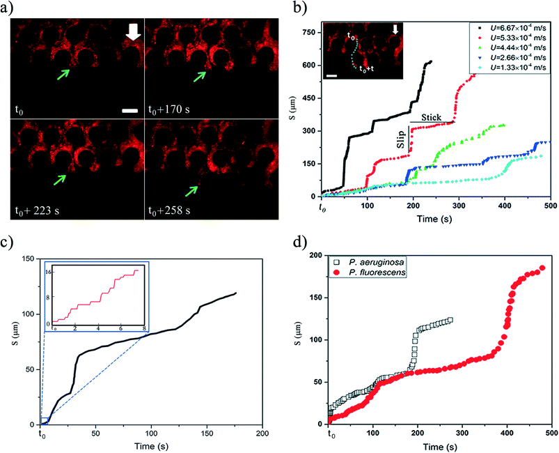
The mature streamers which clog the pore-space, also show the formation of a three-phase front (biomass, pillar walls and liquid media). These streamers start to flow with different velocity from the background flow, as shown previously2 aiding their movement downstream. In this study, we observed that this movement is not smooth, but rather proceeds through a ‘stick-slip’ mechanism (see Fig. 2a for time series data and Video S1†). To further quantify this stick-slip phenomena, we tracked the movement of a Lagrangian point (i.e. a trapped PS particle) in the mature streamer close to the three-phase contact line (Fig. 2b inset). Then we calculated the cumulative arc length (s) that travelled by the Lagrangian point as a function of time  . Fig. 2b depicts the temporal variation of s for various flow speeds. The x-axis for Fig. 2b is translated by a time (t0), which indicates the time elapsed since the beginning of the stick-slip behavior. This was different for different flow rates (Table S1†). Fig. 2b, clearly shows that s increased in steps, indicating a stick-slip behavior. In order to ensure that the stick-slip behavior was not a result of intermittency caused by the pump, a separate experiment was also conducted where gravity assisted pressure driven flow was used. Even in this case, the results demonstrate a stick-slip movement of the mature streamer (Fig. S3†). A further matter of interest would be the deformation of the pillars themselves under the flow loading. To this end, we found that the PDMS micropillars demonstrated no noticeable deformation (within imaging uncertainty) during any of our experiments as confirmed through time-resolved microscopy. Fig. 2b reveals a gross stick-slip behavior, although regions with linear behaviors can also be discerned. Even for these regions, we find that when the time-scales for particle tracking are refined, the stick-slip behavior occurs at smaller time-scales (Fig. 2c). This stick-slip motion was also observed for P. aeruginosa. This shows that this behavior may be a more general mechanical phenomena and independent of the bio-physical issues associated with bacterial strains (Fig. 2d). Another interesting aspect of these experiments is that despite the inherent heterogeneity of biological samples, the overall phenomena are quite repeatable. We found this to be a general aspect of this types of experiments reported both in our previous reported works2,3,7,19 as well as many similar experiments as part of our ongoing research effort. All our experiments were repeated at least 3 times (Table S2†) and similar behavior was observed for different replications (Fig. S4†).
Stick-slip behavior is fairly common between sliding surfaces and often attributed to multiple causes.20–26 Moreover, viscoelastic materials can experience stick-slip or spurt flows due to instabilities.21,27–29 Recently, Gashti et al.30 also noticed that biofilms subject to continuous shear can show a non-monotonic velocity, which they attributed to possible non-Newtonian behavior of the biofilm.30 However, in the current case, this behavior may have far more complex origins due to both the multiphasic nature of the interface and material nonlinearities typical of in situ bacterial streamers. Therefore a more detailed characterization has been left for a future work.
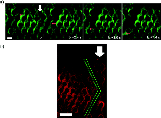
While Fig. 2 depicts the behavior of the advancing front of the clogging biomass, interestingly, the bulk of the clogging biomass also shows interesting behavior. Since, the syringe pump enforces a constant volumetric flow rate (Q), clogging led to increased flow velocities in the clogged portion leading to a non-uniform flow field within the clogged device. This resulted in failure and breakage of mature streamers (Fig. 3a) at critical locations, leading to the formation of water-channels in the biomass, whose length scale was found to be several times that of the pore-length scale (l) (Fig. 3b) (also see Video S2†). Water channel formation depends on the imposed flow speeds. Water channels were observed for velocity scales of 1.33 × 10⁻⁴, 2.66 × 10⁻⁴ and 5.33 × 10⁻⁴ m s−1 after 3 h injection of P. fluorescens bacterial solution while no visible water channel was observed for U = 4.44 × 10⁻⁵ m s−1 (Fig. S5†). Furthermore, water channels also formed in a microchip clogged with P. aeruginosa strongly indicating a mechanical origin of these phenomena (Fig. S6†). The origin of this mode of failure is not yet fully understood.
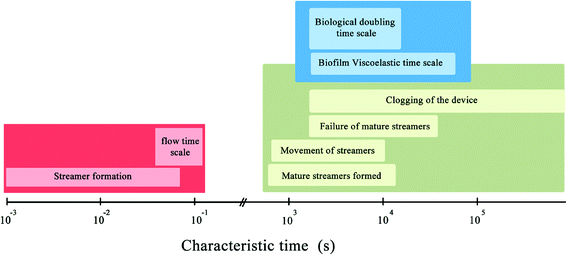
Fig. 4 summarizes the characteristic time-scales of various phenomena observed in our experiments. It is important to note that various events such as clogging of the device, failure and breakage of biomass have the same time-scale as the biological cell doubling time-scale. This suggests that mechanical effects are the dominant contributors to the observed phenomena. Interestingly, no direct correlation between the cross sectional area and the character of the stick-slip behavior was revealed from the experiments. In ‘stick-slip’ motion, during the stick stage, there is no relative motion between two surfaces and during the slip stage motion occurs; this pattern usually repeats itself.31 In this context, note that in spite of the topical similarity of certain regions of the deformation time plot (Fig. 2c and d) with a viscous or viscoelastic material, when taken in totality they do not support a purely material origin of this behavior. This is confirmed through visual data which indicates pronounced sliding at interfaces as well as looking into the myriad jumps in the plots at different time resolutions of the stick-slip plots (Fig. 2c and d). This is because such sudden changes in deformation characteristics are typically associated with instabilities and phase changes whose consequences are often prominently visible in the structure such as necking failure.19 However, in the case of stick-slip, we observe no substantial changes in material constitution near the tracking points with the same regularity as the jumps (which appeared at even finer time scales). Thus, we conclude that the sudden changes in deformations (the spurting ‘slip’ and the sudden arrest of it through ‘stick’) primarily reflect a more global motion aided by the onset and arrest of sliding at the interfaces, further confirmed through microscopy data. Therefore, in this paper the nomenclature of stick-slip as used by Zhang & Li,31 where stick-slip processes are defined for two sliding surfaces has been adopted. A more detailed investigation of the observed phenomena would require substantial bulk and interfacial characterization and is left as an exercise for the future.
In conclusion, in this work we revealed important yet unreported aspects of the dynamics of bacterial streamer induced clogging in a microfluidic device. Particularly, we discovered a highly nonlinear stick-slip type advance of the mature streamer structure which causes the clogging front to move in spurts rather than following a continuous advance. In addition, we also find that even after the onset of substantial clogging in the device, the biomass retains a highly complex dynamic state characterized by marked instabilities and failures which result in extended distinct water channels in the device.
References
- A. Karimi, D. Karig, A. Kumar and A. M. Ardekani, Lab Chip, 2015, 15, 23–42 RSC.
- M. Hassanpourfard, Z. Nikakhtari, R. Ghosh, S. Das, T. Thundat, Y. Liu and A. Kumar, Sci. Rep., 2015, 5, 13070 CrossRef CAS PubMed.
- A. Valiei, A. Kumar, P. P. Mukherjee, Y. Liu and T. Thundat, Lab Chip, 2012, 12, 5133–5137 RSC.
- R. Rusconi, S. Lecuyer, L. Guglielmini and H. A. Stone, J. R. Soc., Interface, 2010, 7, 1293–1299 CrossRef PubMed.
- P. Stoodley, R. Cargo, C. J. Rupp, S. Wilson and I. Klapper, J. Ind. Microbiol. Biotechnol., 2002, 29, 361–367 CrossRef CAS PubMed.
- P. Stoodley, Z. Lewandowski, J. D. Boyle and H. M. Lappin-Scott, Biotechnol. Bioeng., 1998, 57, 536–544 CrossRef CAS PubMed.
- M. Hassanpourfard, X. Sun, A. Valiei, P. Mukherjee, T. Thundat, Y. Liu and A. Kumar, J. Visualized Exp., 2014, e51732 Search PubMed.
- A. Marty, C. Roques, C. Causserand and P. Bacchin, Biofouling, 2012, 28, 551–562 CrossRef PubMed.
- S. Yazdi and A. M. Ardekani, Biomicrofluidics, 2012, 6, 044114 Search PubMed.
- K. Drescher, Y. Shen, B. L. Bassler and H. A. Stone, Proc. Natl. Acad. Sci. U. S. A., 2013, 110, 4345–4350 CrossRef CAS PubMed.
- K. Okuda, T. Kato and K. Ishihara, Oral Dis., 2004, 10, 5–12 CrossRef CAS PubMed.
- C. A. Fux, S. Wilson and P. Stoodley, J. Bacteriol., 2004, 186, 4486–4491 CrossRef CAS PubMed.
- C. E. Stanley, G. Grossmann, X. Casadevall i Solvas and A. J. deMello, Lab Chip, 2016, 16, 228–241 RSC.
- M. Hajnos, J. Lipiec, R. Świeboda, Z. Sokołowska and B. Witkowska-Walczak, Geoderma, 2006, 135, 307–314 CrossRef.
- P. R. Hardoim, L. S. van Overbeek and J. D. v. Elsas, Trends Microbiol., 2008, 16, 463–471 CrossRef CAS PubMed.
- S. Zuber, F. Carruthers, C. Keel, A. Mattart, C. Blumer, G. Pessi, C. Gigot-Bonnefoy, U. Schnider-Keel, S. Heeb and C. Reimmann, Mol. Plant-Microbe Interact., 2003, 16, 634–644 CrossRef CAS PubMed.
- P. Vidhyasekaran and M. Muthamilan, Plant Dis., 1995, 79, 782–786 CrossRef.
- H. Salehizadeh and S. A. Shojaosadati, Biotechnol. Adv., 2001, 19, 371–385 CrossRef CAS PubMed.
- I. Biswas, R. Ghosh, M. Sadrzadeh and A. Kumar, Sci. Rep., 2016, 6, 32204 CrossRef CAS PubMed.
- O. Ben-David, S. M. Rubinstein and J. Fineberg, Nature, 2010, 463, 76–79 CrossRef CAS PubMed.
- M. M. Denn, Annu. Rev. Fluid Mech., 2001, 33, 265–287 CrossRef.
- C. M. Mate, G. M. Mcclelland, R. Erlandsson and S. Chiang, Phys. Rev. Lett., 1987, 59, 1942–1945 CrossRef CAS PubMed.
- D. Orejon, K. Sefiane and M. E. R. Shanahan, Langmuir, 2011, 27, 12834–12843 CrossRef CAS PubMed.
- A. Socoliuc, R. Bennewitz, E. Gnecco and E. Meyer, Phys. Rev. Lett., 2004, 92, 134301 CrossRef CAS PubMed.
- D. Tomanek, W. Zhong and H. Thomas, Europhys. Lett., 1991, 15, 887 CrossRef CAS.
- H. Yoshizawa and J. Israelachvili, J. Phys. Chem., 1993, 97, 11300–11313 CrossRef CAS.
- M. M. Denn, Annu. Rev. Fluid Mech., 1990, 22, 13–34 CrossRef.
- M. M. Denn, Cam Chem Engn, 2008, pp. 199–216, DOI:10.1017/Cbo9780511813177.
- S. Q. Wang and P. A. Drda, Macromolecules, 1996, 29, 2627–2632 CrossRef CAS.
- M. P. Gashti, J. Bellavance, O. Kroukamp, G. Wolfaardt, S. M. Taghavi and J. Greener, Biomicrofluidics, 2015, 9, 041101 CrossRef PubMed.
- S. L. Zhang and J. C. M. Li, Mater. Sci. Eng., A, 2003, 344, 182–189 CrossRef.
Footnote |
| † Electronic supplementary information (ESI) available. See DOI: 10.1039/c6lc01055e |
| This journal is © The Royal Society of Chemistry 2016 |


