
 Open Access Article
 This Open Access Article is licensed under a
 Creative Commons Attribution 3.0 Unported Licence
Smart hydrogels as storage elements with dispensing functionality in discontinuous microfluidic systems†
Sebastian
Haefner
a,
Philipp
Frank
a,
Martin
Elstner
b,
Johannes
Nowak
c,
Stefan
Odenbach
c and
Andreas
Richter
*ab
aPolymeric Microsystems, Institute of Semiconductors and Microsystems, Technische Universität Dresden, 01062 Dresden, Germany. E-mail: andreas.richter7@tu-dresden.de; Fax: +49 351 463 37021; Tel: +49 351 463 36336
bCenter for Advancing Electronics Dresden (cfaed), Technische Universität Dresden, 01062 Dresden, Germany
cChair of Magnetofluiddynamics, Measuring and Automation Technology, Technische Universität Dresden, 01062 Dresden, Germany
First published on 12th September 2016
Abstract
Smart hydrogels are useful elements in microfluidic systems because they respond to environmental stimuli and are capable of storing reagents. We present here a concept of using hydrogels (poly(N-isopropylacrylamide)) as an interface between continuous and discontinuous microfluidics. Their swelling and shrinking capabilities allow them to act as storage elements for reagents absorbed in the swelling process. When the swollen hydrogel collapses in an oil-filled channel, the incorporated water and molecules are expelled from the hydrogel and form a water reservoir. Water-in-oil droplets can be released from the reservoir generating different sized droplets depending on the flow regime at various oil flow rates (dispensing functionality). Different hydrogel sizes and microfluidic structures are discussed in terms of their storage and droplet formation capabilities. The time behaviour of the hydrogel element is investigated by dynamic swelling experiments and computational fluid dynamics simulations. By precise temperature control, the device acts as an active droplet generator and converts continuous to discontinuous flows.
1 Introduction
Lab-on-a-chip systems have great potential for applications in the broad field of scientific research. Scaling down the liquid volume shortens the mixing and reaction time and reduces costs.1 Because of the possibility of handling small volumes of liquid very precisely, microfluidic systems are potentially interesting to speed up applications in chemistry, biochemistry and biology.2–5 A particularly interesting field is the point-of-care application, where a variety of reagents need to be stored on-chip in order to be ready for use by the patient.6,7 This reagent integration is one of the key challenges and two basic principles have been established.8 On the one hand, reagents can be integrated into the device during the fabrication process;9,10 on the other hand, reagents can be integrated into the device after the fabrication process by external injection e.g. with a pump.Alongside the integration of the reagents comes the challenge of carrying out the discharge and dosing of the material. To control the volume of the discharged liquid, valves can be used in combination with a chamber system or a constant liquid flow.11,12 Another possibility is the on-chip integration of liquid-filled glass ampoules as reported for labs-on-discs. After breaking open the ampoule, the dosed volume can be controlled by the time and rotation speed.13 In digital microfluidics, the dosing problem is solved in a way wherein droplets can be dispensed out of a reservoir by a special electrode configuration. By altering this configuration or the number of dispensing steps, the total amount of the dispensed volume can be controlled.14 However, the usage of hydrogels has shown their potential to solve the reagent integration and dosing problem.6,15
Hydrogels are three-dimensional polymer networks with the capability of taking up an aqueous solution containing dissolved ions and molecules. They can be functionalised with varying binding sites to trap small molecules and protect them from degradation.16–19 Hydrogels can store buffer solutions to keep enzymes in an active state,20 they are biocompatible, which is important for cell assays or applications as scaffolds in tissue engineering,21,22 and they are directly accessible from commercial substances. Another advantage is that hydrogels can be lithographically structured by means of photopolymerisation or photocrosslinking. This makes them useable for microsystems engineering.23,24 Furthermore, their mechanical properties25 can be tuned to make them manageable.
Conventional hydrogels store water as well as dissolved molecules and discharge them by diffusion. A special type of hydrogels (known as smart hydrogels) shows a volume phase transition behaviour. This behaviour is based on the low critical solution temperature (LCST), which means that the gels collapse if the environmental temperature exceeds a certain value. During this collapsing process, the hydrogels expel water and dissolved molecules taken up in the swelling process. For poly(N-isopropylacrylamide) PNIPAAm hydrogels in distilled water, the LCST is 32 °C.26–28 Because of the thermal response behaviour, electrical control of the degree of swelling of the hydrogels via an electrochemical interface (e.g. resistive microheater) is possible.29 This possibility has led to the development of micro-electro-mechanical-system elements like valves,30–32 chemostats,33,34 micropumps,35 thermally responsive microlens arrays36 and also an autonomous chemo-fluidic oscillator.37
A diffusion pump with a focus on propagation was published by Richter et al.35 showing that five PNIPAAm segments acting as a sequence of serially connected storage elements are capable of propagating a liquid. Recently published articles demonstrated the application of PNIPAAm hydrogels as storage devices with a dispensing functionality in paper-based microfluidic systems.15,20 However, these publications show the usage of PNIPAAm hydrogels as dynamic memory elements in continuous microfluidic systems.
We introduce here a new approach for using smart hydrogels as dynamic storage elements in microfluidic systems and as an interface from continuous to discontinuous microfluidics. Varying hydrogel sizes in two different channel structures are studied in terms of their dispensing functionality in discontinuous microfluidics. Furthermore, device principles and time behaviour are discussed using computational fluid dynamics (CFD) simulations and dynamic swelling measurements, respectively.
2 Materials and methods
2.1 Materials
N-Isopropylacrylamide (NIPAAm), photoinitiator Irgacure® 2959, N,N′-methylene-bis-acrylamide (BIS), 3-(trimethoxysilyl)propyl methacrylate and sodium fluorescein were purchased from Sigma-Aldrich (St. Louis, USA). NIPAAm was recrystallised from hexane and other chemicals were used as received. The negative dry film photoresist (DFR), developer and rinser for master fabrication were purchased from Elga Europe (Ordyl SY355, Elga Europe, Milan, Italy). Digital temperature sensors DS18S20 (Texas Instruments, Dallas, USA) and Arduino™ Uno micro-controller board (Smart Projects S.R.L., Strambino, Italy) were used for on-chip temperature control. Poly(dimethylsiloxane) (PDMS) RTV-615 for chip fabrication was purchased from Momentive Performance Materials Inc. (Waterford, USA). Span® 80 (Sigma-Aldrich, St. Louis, USA) was added to mineral oil SpectraSyn™ 10 (Exxon Mobile, Irving, USA) for droplet surface stabilisation in 1% w/w relation. For solution preparation and rinsing, deionised water with an electrical conductivity of 0.056 μS cm−1 (Barnstead GENPURE PRO, Thermo Scientific, Langenselbold, Germany) generated by ion exchange was used.2.2 Methods
A hydrogel polymerisation solution, consisting of 2.122 g of NIPAAm monomer and 0.058 g of BIS in 15 mL of water, was mixed in a flask and flushed for 30 min with a stream of argon. After flushing, the solution was transferred into an argon filled glove box and the photoinitiator (0.042 g) was added. The flask was sealed with a septum and protected from light with aluminium foil. For polymerisation, a methacrylate functionalised cover slip was used. For hydrogel polymerisation, the activated cover slip, two glass slides (26 mm × 76 mm, Menzel-Gläser, Gerhard Menzel GmbH, Braunschweig, Germany), a sheet of black poly(ethylene terephthalate) (PET) and a polymer film mask with the hydrogel structures were used. The mask, the activated cover slip and the first glass slide were aligned by hand and the first chamber part was assembled with 3 layers of adhesive tape SCOTCH® Magic Tape (Fig. 1d). The final height of the chamber was 150 μm. After assembling the first chamber part, the components were transferred into a glove box and the chamber was filled with the polymerisation solution (Fig. 1e).
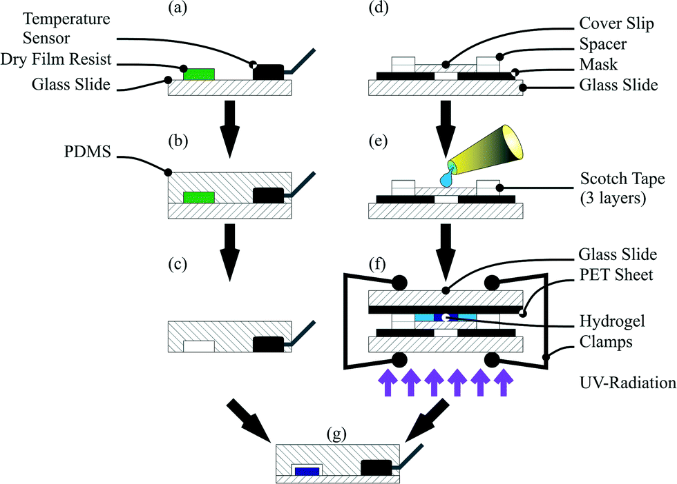 | ||
| Fig. 1 Device fabrication process. PDMS was poured on the master with a temperature sensor (a). After curing, the PDMS chip with the integrated sensor (b) was peeled off from the master (c). The chamber for hydrogel polymerisation was set up (d), filled with the polymerisation solution under an argon atmosphere, sealed with a sheet of black PET, clamped and exposed to UV light for conducting the polymerisation process (f). Finally the hydrogel was integrated and the channel was closed by plasma activation of both components and aligned under a microscope by hand (g). | ||
Finally the polymerisation chamber was closed with a sheet of black PET and the second glass slide and clamped together. For the polymerisation process, the chamber was taken out of the glove box and directly exposed to UV light in an ice cooled water bath following a previously published process.38 Irradiation was carried out for 60 s for every hydrogel size (Fig. 1f). After the polymerisation process, the cover slip with the polymerised hydrogel on top was washed with water and immersed in water overnight to wash out non-polymerised monomers.
![[thin space (1/6-em)]](https://www.rsc.org/images/entities/char_2009.gif) :1 ratio) was added, degassed and cured for 3 h at 60 °C. For sensor integration, the DS18S20 was mounted on the master with hot glue (Fig. 1a and b). After cross-linking, the PDMS chip could be peeled off from the master with the integrated temperature sensor (Fig. 1c). Finally the cover slip with the hydrogel and the PDMS chip were plasma activated, aligned under a microscope by hand and baked for 48 h at 60 °C (Fig. 1g).
:1 ratio) was added, degassed and cured for 3 h at 60 °C. For sensor integration, the DS18S20 was mounted on the master with hot glue (Fig. 1a and b). After cross-linking, the PDMS chip could be peeled off from the master with the integrated temperature sensor (Fig. 1c). Finally the cover slip with the hydrogel and the PDMS chip were plasma activated, aligned under a microscope by hand and baked for 48 h at 60 °C (Fig. 1g).
Device dimensions where chosen starting from the widest channel of 1 mm. Taking into account the fact that hand alignment is required for hydrogel integration, the hydrogel diameter was chosen to be 200 μm smaller than the corresponding channel width (see Fig. 2). Down-scaling of the hydrogel size was conducted to 400 μm diameter, because this hydrogel size can be fabricated and aligned with sufficient precision by hand. By using the dimension relations in Fig. 2, the sizes of the other features are described. For the dimensions of the third chip, the hydrogel diameter used was chosen as the middle value between the largest (800 μm) and the smallest hydrogel diameter (400 μm).
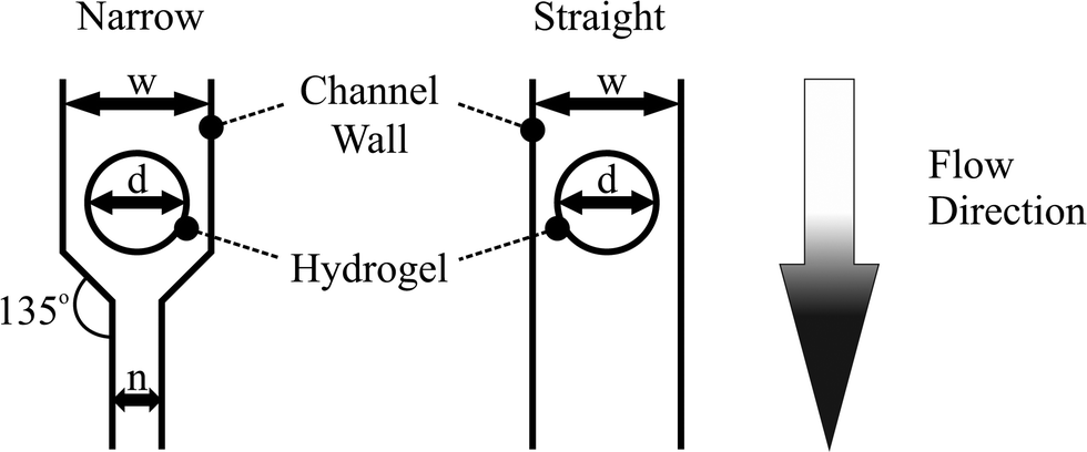 | ||
| Fig. 2 Device dimensions and structures for the active droplet generator. The values for w (channel width) and n (narrow channel width) can be calculated from the hydrogel diameter d. w corresponds to the hydrogel diameter w = d + 200 μm. The width of the narrow channel is n = w/2. | ||
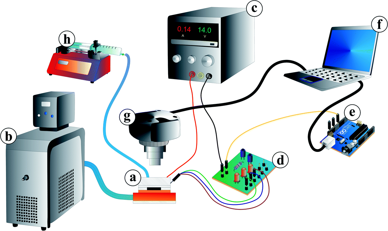 | ||
| Fig. 3 Measuring setup consisting of the microfluidic chip mounted on top of SMD resistors and the resistors on top of a cooler insulated by a 50 μm thick double sided tape (a). The cooler is connected to a thermostat (b) acting as a heat sink. The resistors are coupled to a laboratory voltage supply (c) for Joule heating. The on-chip temperature sensor is wired via a customised control circuit (d) and an Arduino™ Uno board (e) to a computer (f). For observation and video recording, a camera was mounted over the chip (g). For fluid supply, a syringe pump (h) was connected to the microfluidic chip. | ||
For the temperature control, the microfluidic chip (a) was mounted on surface-mount device (SMD) resistors for Joule heating. The resistors were thermally coupled to a water cooling system including a thermostat (Haake A10, Thermo Scientific, Germany) as a heat sink (b). They were also electrically wired to a laboratory power supply (BASETech BT-305, Conrad Electronic, Hirschau, Germany) (c). For controlling the Joule heating, the on-chip temperature sensor was wired via a customised control circuit (d) and a micro-controller board (Arduino™) (e) to a computer (f). The software for the temperature control system was in-house developed Arduino™ software for the proportional-integral-derivative controller and a Python script for the user interface.
For fluorescein excitation, a lamp (KL 1500 LCD, Opto Sonderbedarf GmbH, Gräfelfing/Munich) with a filter (475 ± 21.5 nm, Thorlabs, Dachau/Munich, Germany) for blue light was used (see Fig. 4). Video recording was conducted with a camera (UI-3580LE-C-HQ, IDS Imaging Development Systems GmbH, Obersulm, Germany) (Fig. 3(g)) including a filter (530 ± 17.5 nm, Thorlabs, Dachau/Munich, Germany) adapted to the fluorescein emission spectra. The camera was mounted over the microfluidic chip to observe droplet formation and hydrogel swelling. Video recording via a computer was carried out at 19 fps (frames per second) for swelling kinetic measurements and 49 fps for droplet generation measurements, respectively. For video evaluation, a Matlab® 2014a script for the swelling kinetics measurements and ImageJ open-source software for droplet size measurements were used.
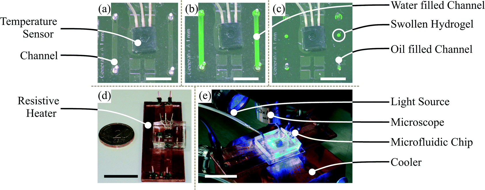 | ||
| Fig. 4 Microfluidic chip with an integrated temperature sensor and hydrogel (a)–(c) (white bar = 5 mm) together with the resistors for Joule heating (d) (black bar = 20 mm) with a close-up view of the measurement setup (e) (white bar = 20 mm). | ||
Fluid supply was enabled by a syringe pump (LA-100, Landgraf Laborsysteme, Langenhagen, Germany) (Fig. 3(h)) connected to the chip with a syringe (12 mL, NORM-JECT® Luer, Henke-Sass Wolf GmbH, Tuttlingen, Germany), a polyethylene tubing (ϕinner = 1 mm, Rotilabo®, Carl Roth GmbH & Co. KG, Karlsruhe, Germany) and dispense needles (ϕinner = 0.838 mm, PK Elektronik Vertrieb GmbH, Ettlingen, Germany).
2.3 Dispensing measurements
The dispensing measurements were conducted by swelling the hydrogels in fluorescein dyed water. After the swelling process, an exchange of the water environment to mineral oil was performed. To monitor the environmental change, video recording was started. Hydrogel shrinking was conducted in a 3-step heating program. First, the on-chip temperature was set to 35 °C (step 1) and directly turned back to 20 °C to stop the heating process (step 2). Because of overshooting from the temperature control system, the shrinking process was initiated for a few seconds. By letting the gel swell again and setting the temperature to 35 °C (step 3) after a few seconds of waiting, the drawback of the skin effect can be avoided (see section 3.1.2). Therefore the maximum water content of the hydrogel can be expelled.After the collapse, an oil flow supplied by a syringe pump was applied at 1 μl min−1 and increased stepwise (1 μl min−1 per step). The flow rate was held for 30 s and the generated water droplets were recorded via the camera setup. After the formation of the sixth droplet, video recording was stopped and droplet measurement was carried out with ImageJ software. Experiments were conducted three times and the droplet size and pinch-off flow rate were averaged. The dispensing functionality was studied for varying hydrogel sizes in two different channel structures (see Fig. 2) to investigate the dispensing behaviour.
2.4 CFD simulations
COMSOL Multiphysics® software was used to carry out stationary 2D microfluidic simulations to explore the velocity field, the velocity direction and also the shear rate for the demonstrated microfluidic channel structures. Structures were designed with AutoDesk® Inventor software. Hydrogels were modelled as cylinders which are transverse to the direction of the flow with a diameter corresponding to the polymerisation mask aperture. Laminar, incompressible flow with no-slip wall boundary conditions at 35 °C was chosen. For the mineral oil with Span® 80, the dynamic viscosity was selected to be 0.067 Pa s (see ESI† S1) and the density to be 0.822 g cm−3. Rheological measurements were conducted with an Anton Paar MCR 301 (Anton Paar, Graz, Austria) rheometer using a cone/plate measurement geometry (49.964 mm diameter, cone opening angle 0.995°). The temperature was varied from 10 °C to 60 °C with a constant shear rate of 100 s−1. The mesh size for the CFD simulations was set to “fine”.2.5 Swelling kinetics
The hydrogels were shrunken in water dyed with fluorescein following the three-step heating process. After the complete shrinking process, video recording was started. 30 s later, the heating was switched off so that the hydrogel can start to swell in the water. The swelling process was observed for 28 min. For the swelling kinetic measurement, a Matlab® image processing script was developed (see Movie S01). The so-defined swelling curves were measured three times, averaged and finally used for calculating the time constant τswell, the degree of swelling Q (based on hydrogel sizes in top view, see eqn (8)) and the cooperative diffusion coefficient Dcoop. Swelling kinetics and coefficient calculations were carried out for all three hydrogel sizes used in the dispensing functionality measurements.3 Results
3.1 Device operation
Smart hydrogels demonstrate storage functionality in microfluidic devices including a dispensing functionality. The dispensing functionality refers to the droplet sizes at different flow rates for the two channel structures and the varying hydrogel sizes. In the following, we divide the device operation into three parts. First we show the hydrogel shrinking in an oil environment and discuss the shrinking related phenomena during this process. In the second part, we demonstrate the dispensing functionality of the microfluidic structures and discuss the basic parameters which influence the dispensing functionality. Finally we compare the amount of stored water inside a hydrogel with the total dispensed water volume during the dispensing procedure by the storage efficiency K.For the dispensing, the three-step heating process (see section 2.3) was executed so that the expelled water forms one water reservoir on top of the shrunken hydrogel. By an oil flow firstly the formed water reservoir is pushed downstream and secondly water droplets can be pinched off. Without heating, no droplets can be formed even at high oil flow rates (see ESI† S3). This behaviour is obvious because of the heterophase (water and oil) system. The oil is hydrophobic and the swollen hydrogel is hydrophilic, resulting in a phase barrier. Without a driving force, the water will not be expelled from the hydrogel. The driving force for water expelling is induced by the heating procedure. But only heating will not result in droplet formation. For this, an additional force is necessary and this force is applied by a convective oil flow (see section 3.1.2).
The dispensing procedure is illustrated in Fig. 5 and the dispensing functionality in Fig. 6. Water expelling after the first heating step is demonstrated in Fig. 5(a) and in Fig. 5(b) the formed water reservoir in the oil flow direction is shown. The convective flow pinches off the water from the hydrogel forming water-in-oil droplets (see Fig. 5(c and d)). The remaining water (see Fig. 5(d)) was used to form the next droplet with an increased flow rate.
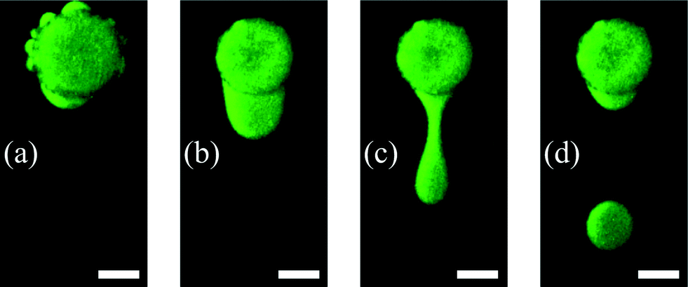 | ||
| Fig. 5 Dispensing process including the first heating step. Because of the fast hydrogel shrinking, water comes out of the pores of the hydrogel forming small satellite water reservoirs (a). After the third heating step one big reservoir is formed on top of the shrunken hydrogel. By an oil flow firstly the formed water reservoir is pushed to the downstream side of the shrunken hydrogel (b) and secondly water droplets can be pinched off (c and d) (scale bar = 200 μm). | ||
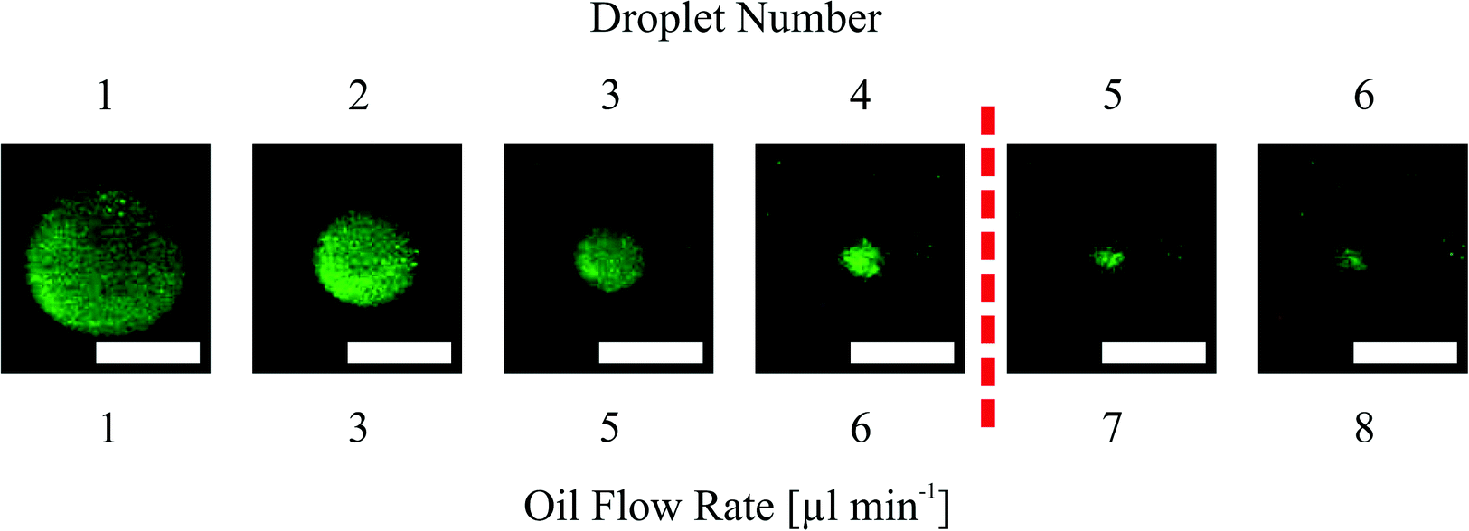 | ||
| Fig. 6 Dispensing functionality by pinched off droplets in a narrowed channel structure with an 800 μm hydrogel. At the far left is shown the first droplet and at the far right the sixth pinched off droplet. The red dashed line indicates the threshold at 1 nl droplet volume. Flow rates beneath the pictures refer to the pinching off flow rates during the experiment (white bar = 200 μm). | ||
The small satellite water reservoir shown in Fig. 5(a) originates from water which was preferentially expelled from the hydrogel through bigger pores or more permeable locations. To form one big reservoir, the 3-step heating procedure has to be executed (see section 2.3). Another necessity for the heating procedure is the prevention of the skin effect. The skin effect results from a dense layer which is formed by collapsed polymer chains. This layer acts as a barrier and prevents the shrinking process by separating the inner swollen part from the outer part. The reason for the skin effect is the time–distance problem of simultaneously occurring diffusion processes where the diffusion coefficient of low molecular weight species is faster compared to the cooperative diffusion of the gel network.39 A stronger degree of collapse for the hydrogel can be observed by comparing the hydrogel diameters in Fig. 5(a) and (b). This difference results from the skin effect which can be prevented by executing the heating protocol as described before, so that the hydrogel shrinkage becomes maximal as well as the size of the expelled water reservoir.
Fig. 7 shows the dispensing characteristics of 6 microfluidic chips. The curves indicate that the dispensing characteristics of all chips are an exponential function based curve progression. The sampled droplet volume is overall smaller for the narrowed channel structure compared to the straight channel structure. By plotting the total amount of dispensed water volume for each device over the polymerisation mask aperture (Fig. 8), it is demonstrated that with a bigger hydrogel (e.g. 800 μm) more water can be sampled (37.26 nl for an 800 μm large gel in the straight channel) which indicates that a bigger hydrogel can store more water than a smaller one (e.g. 10.45 nl for a 400 μm large gel in the straight channel).
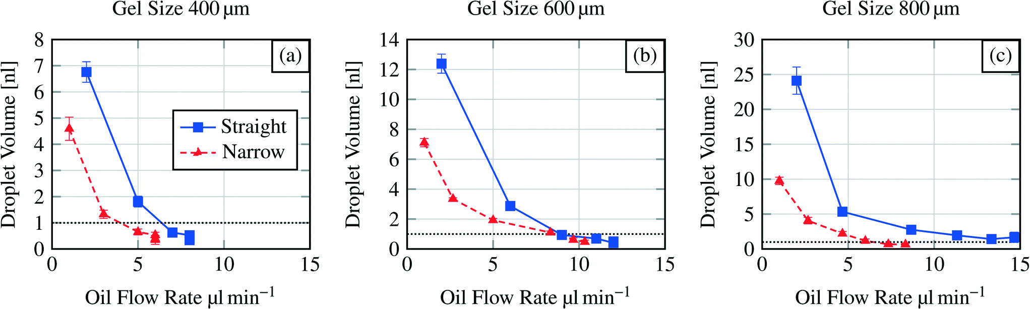 | ||
| Fig. 7 Dispensing functionality for three different hydrogel sizes (400 μm to 800 μm) in various microfluidic channel structures (see Fig. 2). Y-axis scales vary due to exponential curve progression. Dashed horizontal line indicates the threshold at 1 nl droplet volume. | ||
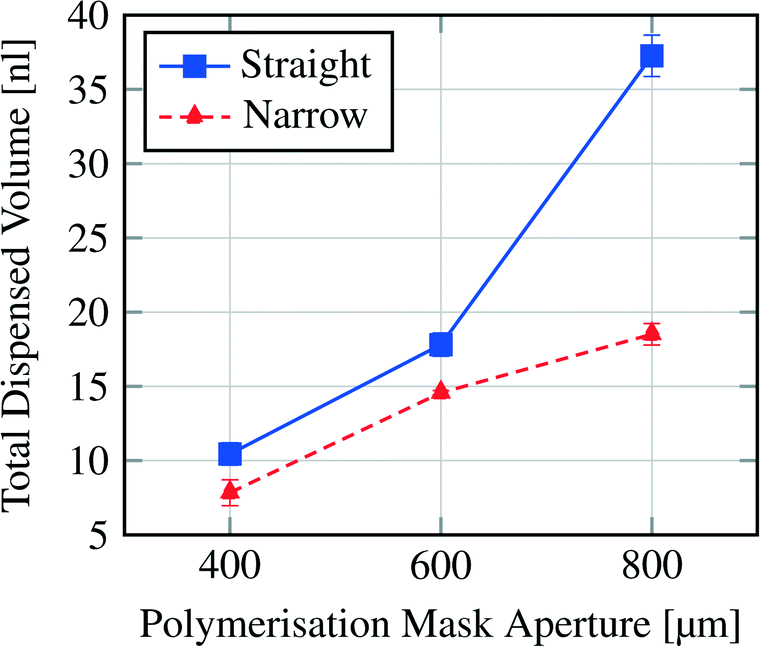 | ||
| Fig. 8 Total dispensed volume per hydrogel size and channel structure (see Fig. 2). | ||
We also compare different microfluidic structures in terms of the size of the first two generated droplets (see Table 1). For the straight channel structure the averaged relation was 4.2:1 whereas for the narrowed channel the relation was 2.6:1. This means that bigger droplets can be generated with the straight channel structure in the first step compared to the narrowed channel structure at a constant hydrogel size. For the 400 μm hydrogel the relation for the first two droplets is nearly the same.
| Chip designation | 1st droplet volume [nl] | 2nd droplet volume [nl] | Droplet volume ratio | Mean |
|---|---|---|---|---|
| Straight, 400 μm gel | 6.76 | 1.81 | 3.7:1 |
4.2:1 |
| Straight, 600 μm gel | 12.39 | 2.87 | 4.3:1 |
|
| Straight, 800 μm gel | 24.11 | 5.34 | 4.5:1 |
|
| Narrow, 400 μm gel | 4.59 | 1.33 | 3.4:1 |
2.6:1 |
| Narrow, 600 μm gel | 7.11 | 3.35 | 2.1:1 |
|
| Narrow, 800 μm gel | 9.75 | 4.06 | 2.4:1 |
|
To conclude on the design parameters, we have shown that with altering the hydrogel size the sampled water volume can be changed and that a variation in the microfluidic channel structure also influences the droplet formation from bigger droplets (straight channel) to smaller (narrowed channel) and the storage efficiency K.
As for the operational parameters, the most important factor is the flow rate. Regarding the exponential curve progression in Fig. 7, we can observe that the sampled volume depends also on the flow rate. For a hydrogel size of 400 μm (Fig. 7(a)) the last three droplets are pinched off at the same flow rate. The formation of more than one droplet at the same flow rate is referred here as a jetting behaviour. In this regime the droplet formation can not be well controlled and therefore should be avoided in applications. The same jetting behaviour was found for the sixth droplet in the straight channel structure for a 600 μm sized hydrogel (Fig. 7b). Standard deviations of the formed droplets are in the order of 1% to 11% indicating that the droplet formation or dispensing functionality is reproducible.
Comparing the pinch off flow rate for the sixth droplet, it can be seen that the flow rate necessary for the pinch off increases with the chip dimensions and differs also for the channel structures. This is an effect of the structures and the increasing dimensions (see section 3.2). One exception is shown for the narrowed channel structure and the hydrogel sizes 600 μm and 800 μm. Here the flow rate for the sixth droplet is higher for the smaller hydrogel. As mentioned before, controlling the devices at higher flow rates is hardly possible.
In the presented study we only investigate the volume of the first six formed droplets. The first structure we investigated was the straight channel with the 800 μm diameter hydrogel where we expected the biggest droplets. Here we found that it is hardly possible to measure formed droplets smaller than a certain size (1 nl threshold, see below). This size was reached for the fifth and sixth droplets. Therefore we set the maximum number of measured droplets to six for each dispensing functionality measurement because for all other structures we expected that the 1 nl threshold will be at lower droplet numbers as what the results also show (see Fig. 7).
Measuring droplet sizes below 1 nl is complicated because of their fast movement through the channel. Fig. 6 indicates that the shape of the formed droplets below 1 nl is influenced by the high velocity. The velocity-influenced shape altering, the fast movement and the size itself sufficiently hinder the precise measurements of the droplet size. Therefore, we conclude that for channel structures with a 400 μm hydrogel the first two generated droplets in one cycle (see Fig. 7(a)) are applicable for further processing. Using a 600 μm hydrogel the first three (straight channel) or four (narrowed channel) droplets and for an 800 μm hydrogel the first four (narrowed channel) or all six (straight channel) droplets should be used regarding the threshold at 1 nl.
Overall the operational parameters allow broad control of the device behaviour. We can state that low flow rates are beneficial for generating well-defined droplet sizes. At higher flow rates the jetting regime becomes dominant generating rather widely distributed droplet sizes.
| Vstor = Aswollen·hswollen − Ashrunken·hshrunken | (1) |
 | (2) |
 | (3) |
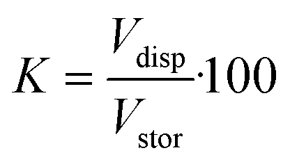
For the devices with a hydrogel of 400 μm diameter we estimate the factor K (eqn (3)). The stored volume is calculated to be 10.51 nl; for the straight channel structure the total amount of dispensed volume is measured to be 10.45 nl and for the narrowed channel 7.84 nl, thus the storage efficiency for the straight channel is 99.4% and that for the narrowed channel is 74.6%. It is important to take into account the fact that the total amount of dispensed volume was calculated after six pinched off droplets so that the storage efficiency shown here is the efficiency after the formation of six droplets. Nevertheless, these results show that for the straight channel structure nearly the whole stored water volume is dispensed after six droplets whereas for the narrowed channel structure ca. 25% remain in the hydrogel.
3.2 Device simulations
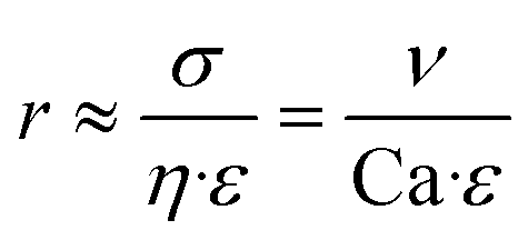
CFD simulations were conducted to investigate the reason for the different dispensing functionalities of the two channel structures (design parameter).Simulations were carried out for the 400 μm hydrogel diameter and a flow rate of 2 μl min−1. For the cross section view, sections were chosen in a way that they are 50 μm or 200 μm away from the outer hydrogel boundary in the flow direction (see Fig. 9). According to droplet generating device theories, the capillary number Ca is important to describe the behaviour of these devices (eqn (4)).40,41
 | (4) |
 | ||
| Fig. 9 Two-dimensional CFD simulations (top view) of the two different channel structures at an oil flow of 2 μl min−1 (a, b). Two channel cross-sections at a distance of 50 μm (c) and 200 μm (d) from the downstream hydrogel boundary showing the shear rate in the channels. Zero for the y-distance direction is set at the channel middle. | ||
Here, η refers to the dynamic viscosity, ν to the velocity of the continuous phase and σ to the interfacial tension. The capillary number describes the relationship between forces generated by the continuous flow and forces due to the surface tension. Therefore, a certain velocity of the continuous phase is required to form water-in-oil droplets. The capillary number relates to the droplet diameter so that at higher capillary numbers smaller droplets are formed (eqn (5)).42
 | (5) |
Here, r refers to the droplet radius and ε to the shear rate. In the demonstrated devices, a gradient in the velocity field (=shear rate) induces shear stress on the water expelled by the hydrogels. The equation implies that with a higher shear rate of the continuous phase the droplet radius decreases.
Results of the 2D simulations are shown in Fig. 9 together with cross-section views of the shear rate. The arrows in the plots represent the velocity field magnitude and direction. Following the simulations and especially the cross-section views of the shear rates (channel middle for the y-direction is set to zero) it is demonstrated that the shear rate for the narrowed structure is around two times higher (∼19 s−1) than the shear rate for the straight channel structure (∼9 s−1) at the same position (channel middle, 50 μm downstream hydrogel boundary).
200 μm downstream the hydrogel boundary, the shear rate decreases in the channel middle to ∼6 s−1 (narrowed channel) or ∼3 s−1 (straight channel), respectively, which is twice as much. A bigger and more important distinction occurs at the site walls of the channel structures. Here, the shear rate constitutes for the narrowed channel to ∼55 s−1 and differs sevenfold for the straight channel (∼8 s−1). Therefore, stronger shear stress pinches an expelled water droplet in the narrowed structure in this part of the channel.
The overall maximum shear rate emerges for both channel structures at the most narrow channel parts. The distance between the hydrogel boundary and the channel wall is 100 μm following the design in Fig. 2. For the same hydrogel size, the maximum shear rate is equal, independent from the channel structure.
Referring to eqn (5) showing that with higher shear rates (=velocity field gradient) the droplet size decreases, the varying dispensing behaviour of the channel structures becomes clear. In the narrowed channel we have obtained at the same flow rate higher shear rates and therefore higher shear stress resulting in the formation of smaller droplets. Another difference is observed for the directions of the velocity field. The flow direction also alters the size of the formed droplets at the same capillary number.43 Comparing the two channel structures with common droplet generating microfluidic structures, the narrowed channel corresponds to a flow-focusing device and the straight channel corresponds to a co-flow/coaxial-flow structure.
3.3 Hydrogel time behaviour
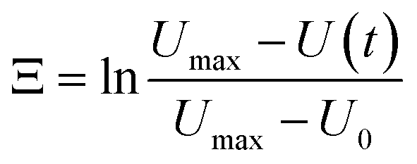
The most crucial characteristics of storage devices are the writing and read-out time. For the devices introduced here the writing time is determined by the swelling time constant τswell of the hydrogels (loading speed) and the read-out time by the dispensing time including the shrinking process. The swelling and shrinking processes are diffusion-based processes and are equally fast.44 Nevertheless, there are scenarios in which the swelling and shrinking time behaviour can be different. These scenarios are a) counter forces on the expanding hydrogel, b) covalent attachment of the hydrogel to a surface and c) limitations in the swelling medium supply. In our microfluidic devices we have on the one hand a counter force on the expanding hydrogel by the channel top as soon as the swelling hydrogels touches the top of the channel. On the other hand the hydrogels are also covalently attached to the glass surface. Therefore scenarios a) and b) apply to our system leading to a slow swelling process compared to the shrinking process. Consequently the shrinking and droplet formation is fast compared to the swelling process (see ESI† S5), so the most time consuming step for device performance is the loading process. Hence we focus on the swelling process for the hydrogel characterisation.From the swelling kinetics theory published by Tanaka et al.44,45 it is known that the time constant for the swelling process can be calculated from the swelling curves obtained by measuring the degree of swelling as a function of time (see S1† and Fig. 10d). Eqn (6) describes the change of the hydrogel size Ξ in dependence on time due to the swelling process.39
 | (6) |
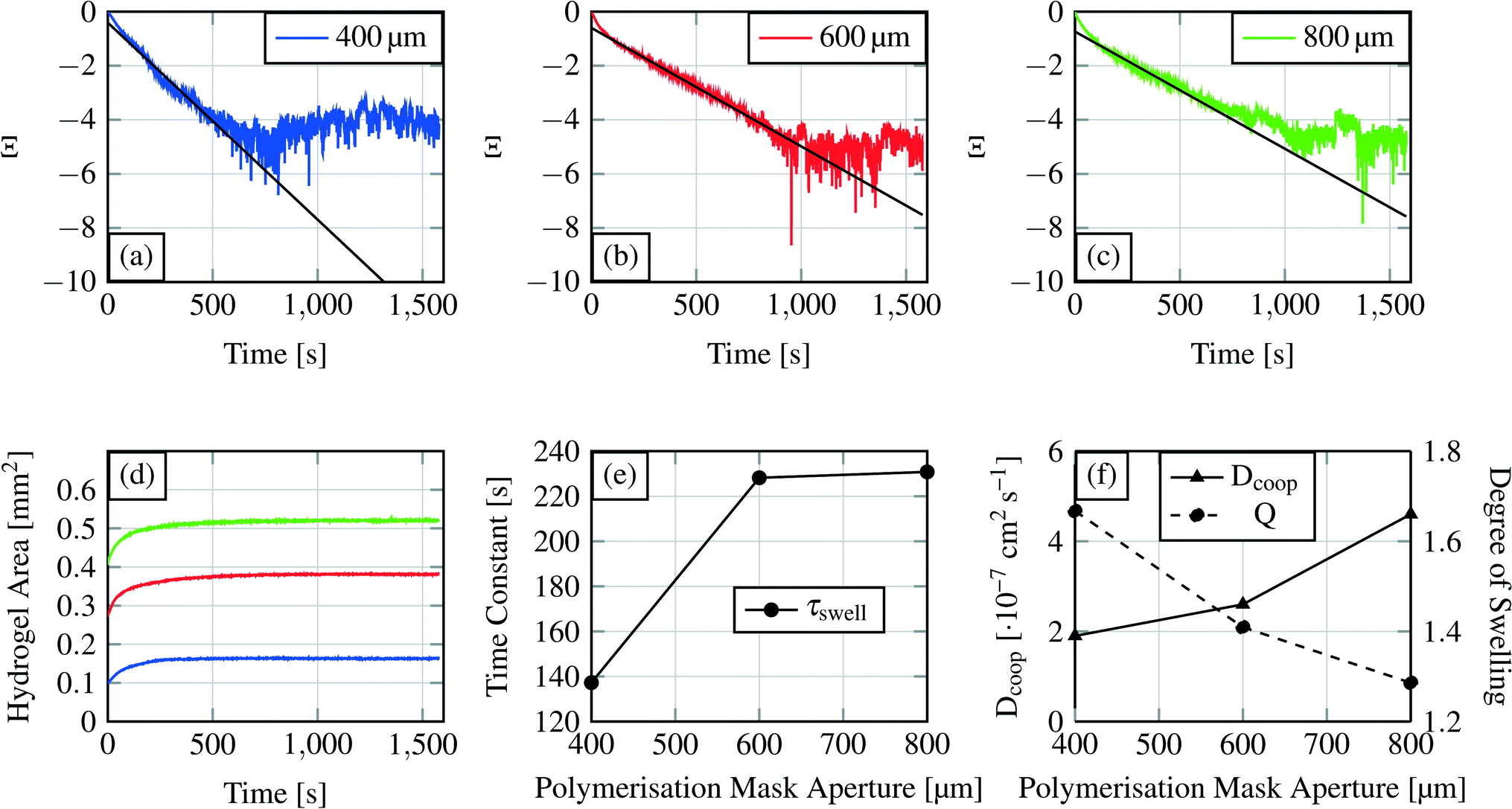 | ||
| Fig. 10 Swelling curves (d) for each hydrogel size and the recalculated swelling curves following eqn (6)) (a–c). The first part of these curves was used for linear curve fitting and calculation of the time constant for the swelling process. Time constant τ for the different hydrogel sizes is shown in (e), where the time constants are plotted over the polymerisation mask aperture. The degree of swelling and the cooperative diffusion coefficient are shown in (f). | ||
U max refers to the maximum size of the hydrogel, U(t) to the hydrogel size at a certain time t and U0 to the hydrogel size at the beginning of the swelling process. With a linear fit in the corresponding curves shown in Fig. 10(a–c) the time constant can be calculated (eqn (7)).
 | (7) |
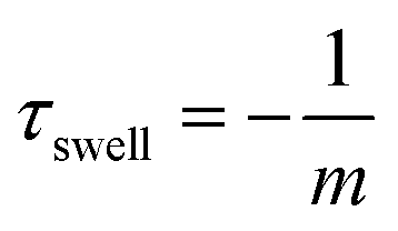
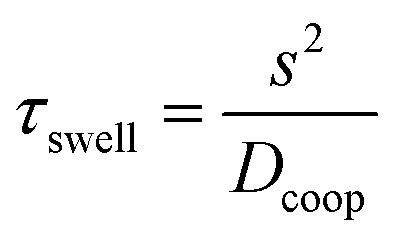
From the linear fit, we can estimate the slope m and calculate the time constant τswell, which scales also with the gel dimensions (see eqn (10)). The time constants for the different hydrogel sizes are plotted in Fig. 10(e). The graph shows that with increasing hydrogel size the time constant also increases. The smallest hydrogel exhibits the shortest time constant which implies that the smallest hydrogel is also the fastest one in the swelling process. Taking into account the fact that the swelling process is a diffusion-driven process, this result seems apparent.
Subsequently we compare the hydrogel with an electric capacitance and its dynamic characteristics.46 The calculated time constant refers to the time required to achieve 63% of the final degree of swelling. In analogy to electronics, a capacitor is considered as fully loaded after a time of 5 × τswell (=99% loaded). For the device time behaviour we concluded that a device with a 400 μm gel needs around 11 min (660 s) as the writing time and devices with the other two hydrogel sizes around 19 min (1140 s).
The similarity of the time constants for 600 μm and 800 μm hydrogels results from a large difference in the cross-linking density of these hydrogels. For the explanation we calculate the cooperative diffusion coefficient Dcoop and the degree of swelling Q (eqn (8)).
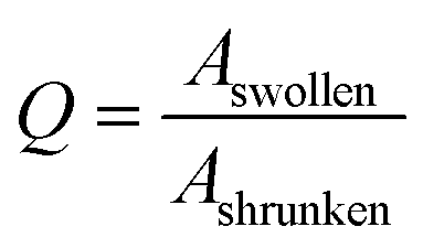 | (8) |
In eqn (8) the Aswollen (top view area of the swollen hydrogel) and the sizeshrunken (top view area of the shrunken hydrogel) are the sizes of the hydrogels in the beginning of the swelling process (Fig. 10d) and the biggest size in the swelling curve, respectively. For the calculation of the cooperative diffusion coefficient, the following equation was used (eqn (9)).39
 | (9) |
Here, Dcoop refers to the cooperative diffusion coefficient and l to the half of the polymerisation mask aperture.
The cross-linking density affects the cooperative diffusion coefficient, the time constant and also the degree of swelling. With higher cross-linking density the cooperative diffusion coefficient will increase whereas the time constant and the degree of swelling will decrease.39Fig. 10(e and f) demonstrate this behaviour. Dcoop increases nearly linear with increasing hydrogel size which is a hint for an increasing cross-linking density.39 From previous publications it is known that the cooperative diffusion coefficient for PNIPAAm lies at 2.3 × 10⁻⁷ to 3.6 × 10⁻⁷ cm2 s−1 so the shown results fit well to this data.47 With higher cross-linking density the degree of swelling decreases so that a hydrogel reaches its maximum degree of swelling faster.
The degree of swelling and the cooperative diffusion coefficient imply that the time constant similarity for the two bigger gels is an effect of the increasing cross-linking density. A bigger hydrogel exhibits a longer time constant than smaller hydrogels if their cross-linking densities are comparable. If the cross-linking densities differ too much (e.g. a higher density for the bigger gel) a bigger hydrogel can become faster in the swelling process than a smaller gel. The reason for the cross-linking density differences lies in the polymerisation process. At the same polymerisation time, a hydrogel with a bigger polymerisation mask aperture will develop a higher degree of cross-linking compared to the one with a smaller mask aperture. This observation gives us the possibility to alter a material parameter (device parameters, see section 3.1.2) by the mask aperture or the polymerisation time. The cooperative diffusion coefficient describes a material parameter inside a device.
With the results presented in this section we demonstrated that the mask aperture influences the hydrogel properties and thereby also a material parameter. The reasons for the influence of the mask aperture on the cross-linking density are the light scattering effects at the mask boundaries and diffraction. The effect can be compared with a standard photolithography process. Here it is almost known that the exposure time required for suitable feature sizes depends on the mask aperture. With decreasing feature sizes the exposure time has to be increased. For the photopatterning of hydrogels, the effect is quite similar. We used a black PET sheet to absorb scattered light to enhance the pattern fidelity.38 Therefore, less light will be available for starting the polymerisation process at smaller mask apertures. We chose a constant exposure time for all three hydrogel sizes causing the bigger hydrogels to be overexposed by tendency. The over exposure of the hydrogels becomes apparent when the time constants are calculated for each system as shown in section 3.1.1. The by tendency over exposure of bigger hydrogels needs to be considered when dimensioning a system and can be specifically used to adjust the dynamic properties.
In a previous publication the authors show that the size of a uniform UV beam used for photopatterning of hydrogels influences the polymer formation process. As Park et al.48 stated, there are still open questions regarding the process. They expressed the assumptions that the gelation and the sample thickness (chamber height) affect the polymerisation procedure. In the first investigations we found that the Young's modulus of photo-patterned PNIPAAm hydrogels differs for the boundary and the gel's centre. At the boundary, the gel is softer than in the middle, indicating that at the boundary the cross-linking density is smaller. We assume that this is also a result of scattered light at the mask boundaries.
4 Conclusions
We introduce a new microfluidic device concept which allows the storage and also dispensing of aqueous solutions and reagents on a chip. By combining hydrogels with the approach of discontinuous microfluidic systems, the devices show promising features for microfluidic application like well-defined volume and reagent storage and the possibility of dispensing the stored molecules, all these in an evaporation-protected oil environment. With a complex setup for precise temperature control, it is possible to collapse the hydrogels and form water-in-oil droplets, which makes this microfluidic system also a continuous to discontinuous microfluidic interface like a droplet generating structure. Using simulations and swelling measurements different parameters like material parameters (hydrogel polymerisation), time behaviour and dispensing functionality were investigated. With the inherent scalability, this device concept can become interesting for solving microfluidic storing problems.Currently the time behaviour of the device is limited by the swelling process. However, because of the diffusion-based time performance hydrogel technology provides the possibility of scaling the time behaviour by the device dimensions. By down-scaling the system dimensions and especially the hydrogel size, the swelling time performance and therefore the device time behaviour can be sped up (see eqn (10)). The characteristic time constant τswell scales to the square of the characteristic diffusion dimension s of the gel component.49 For example, with a two times reduction in the gel size the required time for swelling will be reduced by a factor of four. In other words, if we scale down the 400 μm hydrogel considered in the measurements to 50 μm (=factor of eight) the time constant will decrease from 132 s to 2 s. Fabrication of hydrogels with a diameter of 50 μm can be conducted by ink-jet printing technologies.50 Another possibility of accelerating the hydrogel swelling is the usage of copolymer hydrogels.
 | (10) |
The idea for the usage of the demonstrated device is to use the hydrogel one time. For example, if some molecules like enzymes are stored in the hydrogel which were afterwards dispensed as dissolved molecules in the droplet, a re-usage of the hydrogel will not be meaningful. Furthermore, cross-contamination of solutions is possible, as hydrogels never deswell completely and contain therefore some amounts of the stored substances. In principle, the hydrogel can be reused by flushing the channel with water to change the gel environment from oil to water. The gel will swell again and further droplets can be generated.
Taking into account the fact that the demonstrated combination of discontinuous microfluidic systems and stimuli-responsive hydrogels in a closed channel system is a new approach in microfluidics, ongoing investigations and technology nodes are challenging. Technology and method development for down-scaling and high integration of smart hydrogels have to be focused on in future efforts. A resistive heater platform for precise hydrogel adjustment becomes necessary for addressing specific hydrogels e.g. in a hydrogel array configuration. Another challenge in the platform technology development will be the control of the droplet movement. Abate et al.51 showed the possibility of using micropneumatics for controlling the flow of water-in-oil droplets on a chip. A combination of the micropneumatic platform with the demonstrated device would result in a versatile hybrid system capable of storing defined liquid volumes on a chip in a solid manner (compared to a chamber-based microfluidic memory storage device52 with the capability of read-out).
The introduced device is based on a new concept and therefore we do not claim to foresee the importance or relevance of the demonstrated devices for the microfluidic community. But we think that there are some applications for which such devices become interesting. As already mentioned, hydrogels are well known to act as size-selective capturing matrices of low-molecular-weight biomarkers, making them interesting for cancer-related studies. Hydrogels can be used to selectively extract biomarkers out of a complex environment. By changing the environment to oil after molecule extraction, the volume and the place where the molecules are stored can be discretised. Such a discretisation or separation is important to e.g. prevent cross-reactions during a biochemical assay. By using the dispensing functionality, the selectively captured biomarkers can be read-out and used for further investigations.
Furthermore, hydrogels are known to stabilise sensitive biological materials like enzymes so that they stay in an active state. With the here shown concept, such sensitive materials can be integrated into a microfluidic chip and de-immobilised by heating the hydrogels in a controlled manner so that water-in-oil droplets were formed with re-mobilised enzymes also capable of performing ongoing biochemical studies.
Finally as mentioned before, these devices are also interesting for basic studies on hydrogel-related shrinking phenomena. Hydrogel shrinking in an oil environment allows the shrinking process to be investigated in a new way. We were able to visualize the inhomogeneous water expelling from the hydrogel which can be explained by the formation of spatial inhomogeneities in the polymer network due to phase separation during the shrinking process of the hydrogel.53
Acknowledgements
The authors would like to thank Gerald Hielscher (Electronic Packaging Laboratory, Technische Universität Dresden) for preparing the photomasks. Further, the authors thank the Deutsche Forschungsgemeinschaft (Research Training Group 1865 ‘Hydrogel based Microsystems’) and the Center for Advancing Electronics Dresden (cfaed) for financial support.References
- E. K. Sackmann, A. L. Fulton and D. J. Beebe, Nature, 2014, 507, 181–189 CrossRef CAS PubMed.
- A. H. Ng, M. D. Chamberlain, H. Situ, V. Lee and A. R. Wheeler, Nat. Commun., 2015, 6, 7513–7525 CrossRef CAS PubMed.
- L. Martin, M. Meier, S. M. Lyons, R. V. Sit, W. F. Marzluff, S. R. Quake and H. Y. Chang, Nat. Methods, 2012, 9, 1192–1194 CrossRef CAS PubMed.
- S. R. Lockery, S. E. Hulme, W. M. Roberts, K. J. Robinson, A. Laromaine, T. H. Lindsay, G. M. Whitesides and J. C. Weeks, Lab Chip, 2012, 12, 2211–2220 RSC.
- A. Knauer, A. Eisenhardt, S. Krischoka and J. M. Koehler, Nanoscale, 2014, 6, 5230–5239 RSC.
- M. Hitzbleck and E. Delamarche, Chem. Soc. Rev., 2013, 42, 8494–8516 RSC.
- A. W. Martinez, S. T. Phillips and G. M. Whitesides, Anal. Chem., 2010, 82, 3–10 CrossRef CAS PubMed.
- C. D. Chin, V. Linder and S. K. Sia, Lab Chip, 2012, 12, 2118–2134 RSC.
- M. Focke, D. Kosse, C. Müller, H. Reinecke, R. Zengerle and F. von Stetten, Lab Chip, 2010, 10, 1365–1386 RSC.
- T. van Oordt, Y. Barb, J. Smetana, R. Zengerle and F. von Stetten, Lab Chip, 2013, 13, 2888–2892 RSC.
- D. B. Weibel, A. C. Siegel, A. Lee, A. H. George and G. M. Whitesides, Lab Chip, 2007, 7, 1832–1836 RSC.
- Y. Morimoto, Y. Mukouyama, S. Habasaki and S. Takeuchi, Micromachines, 2016, 7, 1–10 CrossRef.
- J. Hoffmann, D. Mark, S. Lutz, R. Zengerle and F. von Stetten, Lab Chip, 2010, 10, 1480–1484 RSC.
- K. S. Elvira, R. Leatherbarrow, J. Edel and A. deMello, Biomicrofluidics, 2012, 6, 022003 CrossRef PubMed.
- R. R. Niedl and C. Beta, Lab Chip, 2015, 15, 2452–2460 RSC.
- A. Patanarut, A. Luchini, P. J. Botterell, A. Mohan, C. Longo, P. Vorster, E. F. Petricoin III, L. A. Liotta and B. Bishop, Colloids Surf., A, 2010, 362, 8–19 CrossRef CAS PubMed.
- A. Luchini, D. H. Geho, B. Bishop, D. Tran, C. Xia, R. Dufour, C. Jones, V. Espina, A. Patanarut, W. Zhu, M. Ross, A. Tessitore, E. F. Petricoin III and L. A. Liotta, Nano Lett., 2008, 8, 350–361 CrossRef CAS PubMed.
- A. Patanarut, A. Luchini, P. J. Botterell, A. Mohan, C. Longo, P. Vorster, E. F. Petricoin III, L. A. Liotta and B. Bishop, Nano Res., 2008, 1, 502–518 CrossRef PubMed.
- C. Longo, G. Gambara, V. Espina, A. Luchini, B. Bishop, A. S. Patanarut, E. F. Petricoin III, F. Beretti, B. Ferrari, E. Garaci, A. D. Pol, G. Pellacani and L. A. Liotta, Exp. Dermatol., 2011, 20, 29–34 CrossRef PubMed.
- H. T. Mitchell, S. A. Schultz, P. J. Costanzo and A. W. Martinez, Chromatography, 2015, 2, 436–451 CrossRef.
- A. Khademhosseini and R. Langer, JARE Data Rep., 2007, 28, 5087–5092 CAS.
- Y. Haraguchi, T. Shimizu, M. Yamato and T. Okano, RSC Adv., 2012, 2, 52184–52190 RSC.
- J. Hoffmann, M. Plötner, D. Kuckling and W.-J. Fischer, Sens. Actuators, A, 1999, 77, 139–144 CrossRef CAS.
- D. J. Beebe, J. S. Moore, J. M. Bauer, Q. Yu, R. H. Liu, C. Devadoss and B.-H. Jo, Nature, 2000, 404, 588–590 CrossRef CAS PubMed.
- E. Ahmed, JARE Data Rep., 2015, 6, 105–121 CAS.
- M. Heskins and J. E. Guilett, J. Macromol. Sci., Chem., 1968, 2, 1441–1455 CrossRef CAS.
- K. Tauer, D. Gau, S. Schulze, A. Völkel and R. Dimova, Colloid Polym. Sci., 2009, 2, 299–312 Search PubMed.
- M. Andersson, A. Axelsson and G. Zacchi, J. Controlled Release, 1998, 50, 273–281 CrossRef CAS PubMed.
- A. Richter, D. Kuckling, S. Howitz, T. Gehring and K.-F. Arndt, J. Microelectromech. Syst., 2003, 12, 748–753 CrossRef.
- J. Wang, Z. Chen, M. Mauk, K.-S. Hong, M. Li, S. Yang and H. H. Bau, Biomed. Microdevices, 2005, 7, 313–322 CrossRef CAS PubMed.
- N. Idota, A. Kikuci, J. Kobayashi, K. Sakai and T. Okano, Adv. Mater., 2005, 17, 2723–2727 CrossRef CAS.
- A. D. Jadhav, B. Yan, R.-C. Luo, L. Wei, X. Zhen, C.-H. Chen and P. Shi, Biomicrofluidics, 2015, 9, 1–12 CrossRef PubMed.
- A. Richter, J. Wenzel and K. Kretschmer, Sens. Actuators, B, 2007, 125, 569–573 CrossRef CAS.
- A. Richter, A. Türke and A. Pich, Adv. Mater., 2007, 19, 1109–1112 CrossRef CAS.
- A. Richter, S. Klatt, G. Paschew and C. Klenke, Lab Chip, 2009, 9, 613–618 RSC.
- X. Zeng, C. Li, D. Zhu, H. J. Cho and H. Jiang, J. Micromech. Microeng., 2010, 20, 115035 CrossRef.
- G. Paschew, J. Schreiter, A. Voigt, C. Pini, J. P. Chávez, M. Allerdißen, U. Marschner, S. Siegmund, R. Schüffny, F. Jülicher and A. Richter, Adv. Mater. Technol., 2016, 1, 1600005 CrossRef.
- S. Haefner, M. Rohn, P. Frank, G. Paschew, M. Elstner and A. Richter, Gels, 2016, 2, 1–11 CrossRef.
- Hydrogel Sensors and Actuators, ed. G. Urban, Springer Series on Chemical Sensors and Biosensors, Heidelberg, Dordrecht, London, New York, 1st edn, 2009 Search PubMed.
- C. N. Baroud, F. Gallaire and R. Dangla, Lab Chip, 2010, 10, 2032–2045 RSC.
- S.-Y. Teh, R. Lin, L.-H. Hung and A. P. Lee, Lab Chip, 2008, 8, 198–220 RSC.
- T. Thorsen, R. W. Roberts, F. H. Arnold and S. R. Quake, Phys. Rev. Lett., 2001, 86, 4163–4166 CrossRef CAS PubMed.
- A. R. Abate, A. Poitzsch, Y. Hwang, J. Lee, J. Czerwinska and D. A. Weitz, Phys. Rev. E: Stat., Nonlinear, Soft Matter Phys., 2009, 80, 026310 CrossRef CAS PubMed.
- T. Tanaka and D. J. Fillmore, J. Chem. Phys., 1979, 70, 1214–1218 CrossRef CAS.
- Y. Li and T. Tanaka, J. Chem. Phys., 1990, 92, 1365–1371 CrossRef CAS.
- Aufgaben und Lösungen zur Schaltungsdarstellung und Simulation elektromechanischer Systeme, ed. U. Marschner and R. Werthschützky, Springer Vieweg, Heidelberg, Berlin, 1st edn, 2015 Search PubMed.
- S. H. Gehrke, Adv. Polym. Sci., 1993, 110, 81–144 CrossRef CAS.
- S. Park, D. Kim, S. Y. Ko, J.-O. Park, S. Akella, B. Xu, Y. Zhang and S. Fraden, Lab Chip, 2014, 14, 1551–1563 RSC.
- A. Richter, G. Paschew, S. Klatt, J. Lienig, K.-F. Arndt and H.-J. P. Adler, Sensors, 2008, 8, 561–581 CrossRef CAS.
- L. Pan, G. Yu, D. Zhai, H. R. Lee, W. Zhao, N. Liu, H. Wang, B. C.-K. Tee, Y. Shi, Y. Cui and Z. Bao, Proc. Natl. Acad. Sci. U. S. A., 2012, 109, 9287–9292 CrossRef CAS PubMed.
- A. R. Abate, J. J. Agresti and D. A. Weitz, Appl. Phys. Lett., 2010, 96, 1–4 CrossRef.
- T. Thorsen, S. J. Maerkl and S. R. Quake, Science, 2002, 298, 580–584 CrossRef CAS PubMed.
- S. Takata, K. Suzuki, T. Norisuye and M. Shibayama, Polymer, 2002, 43, 3101–3107 CrossRef CAS.
Footnote |
| † Electronic supplementary information (ESI) available: Movie S01: the captured swelling process of an 800 μm hydrogel using a standard camera through the eyepiece of a microscope (frame rate of 19 fps) including image processing results. See DOI: 10.1039/c6lc00806b |
| This journal is © The Royal Society of Chemistry 2016 |