
 Open Access Article
 This Open Access Article is licensed under a
 Creative Commons Attribution 3.0 Unported Licence
Oscillatory multiphase flow strategy for chemistry and biology
Milad
Abolhasani
and
Klavs F.
Jensen
*
Department of Chemical Engineering, Massachusetts Institute of Technology, 77 Massachusetts Avenue, 66-342, Cambridge, MA 02139, USA. E-mail: kfjensen@mit.edu; Web: http://web.mit.edu/jensenlab
First published on 11th July 2016
Abstract
Continuous multiphase flow strategies are commonly employed for high-throughput parameter screening of physical, chemical, and biological processes as well as continuous preparation of a wide range of fine chemicals and micro/nano particles with processing times up to 10 min. The inter-dependency of mixing and residence times, and their direct correlation with reactor length have limited the adaptation of multiphase flow strategies for studies of processes with relatively long processing times (0.5–24 h). In this frontier article, we describe an oscillatory multiphase flow strategy to decouple mixing and residence times and enable investigation of longer timescale experiments than typically feasible with conventional continuous multiphase flow approaches. We review current oscillatory multiphase flow technologies, provide an overview of the advancements of this relatively new strategy in chemistry and biology, and close with a perspective on future opportunities.
Introduction
For several decades, researchers across multiple disciplines, particularly chemistry, biology, and engineering, have manipulated fluids at micro and milli-meter scale to prepare or analyze samples.1–4 Shrinking the sample volume from milliliters to micro/nano liters, followed by further manipulation of the reagents in flow has enabled fundamental investigations and practical applications.5–8 Single-phase continuous flow in sub millimeter channels was quickly realized to have challenges of unwanted Taylor dispersions, poor mixing and mass transfer as well as potential clogging by cells and particulates.9–12 To circumvent these challenges, researchers separated the fluid of interest into small segments or fully entrapped segments within an inert continuous phase, which increased mixing and reduced (or completely avoided) contact with the channel walls.13–15 One of the main promises of the resulting multiphase microfluidic technologies has been the “high-throughput screening”, that is, obtaining a large number of output parameters associated with different aspects of a process of interest in a faster and more efficient manner, compared to batch scale techniques (Fig. 1a).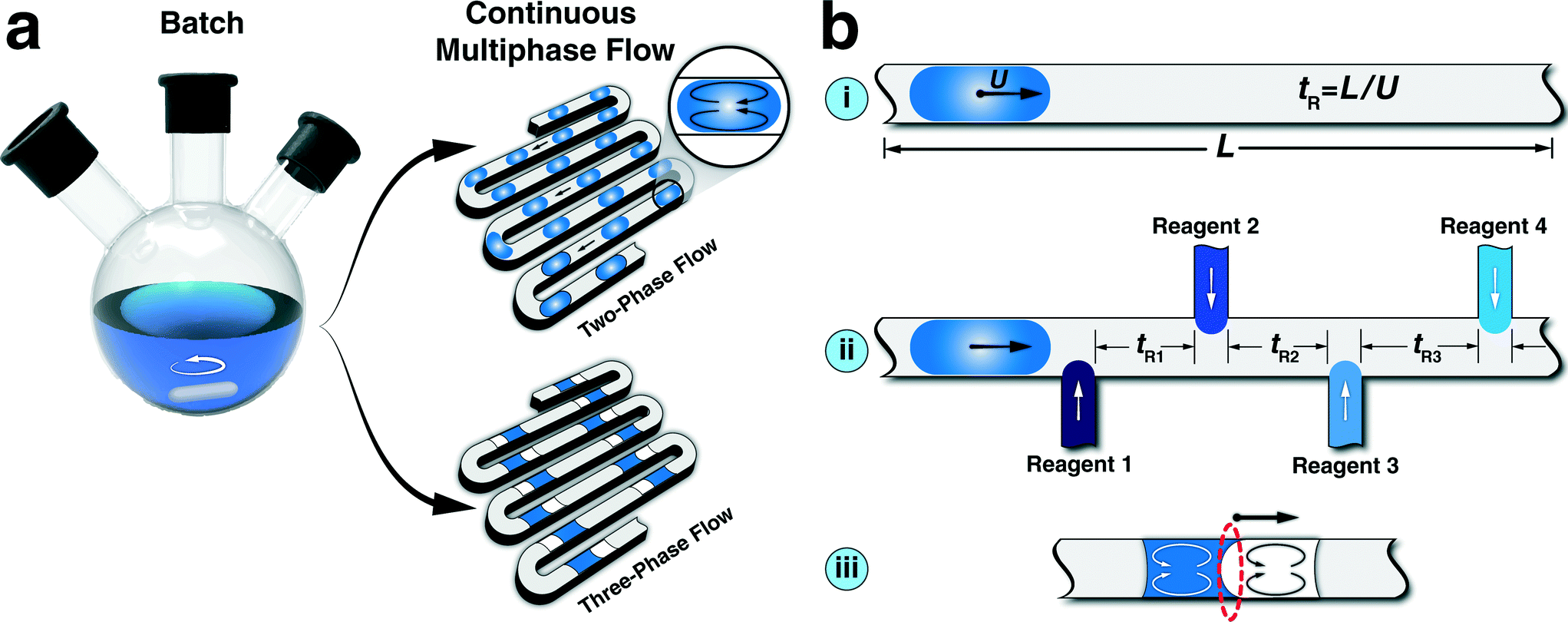 | ||
| Fig. 1 (a) Continuous multiphase flow strategy as an alternative for conventional batch processes. (b) Inherent challenges of continuous multiphase flow reactors for screening of physical, chemical, and biological processes: (i) limited residence time and direct correlation between mixing and reaction times due to the constant length of the reactor; (ii) in-series hard-wired residence times for multi-step processes; (iii) limited available interfacial area for bi-phasic interfacial reactions, highlighted in red, that is the semi-spherical cap between the two immiscible phases. | ||
A multitude of continuous multiphase microfluidic techniques have been developed for high-throughput studies of biological assays,16–20 single cell encapsulation,21 screening and optimization of protein crystallization,22,23 picoinjections at kilohertz frequencies,24 DNA/protein assays,25,26 screening of photosensitizer activity,27 kinetic studies of (bio)chemical reactions,28 screening of chemical reactions,29–34 characterization of thermodynamic properties of gas–liquid processes,35–40 and studies of micro/nanoparticle synthesis.41–53 Different aspects of continuous multiphase microfluidics have already been discussed in multiple comprehensive reviews.13,15,54–56 In this Frontier article, we first discuss challenges of continuous multiphase flow platforms for screening and optimization of (bio) chemical processes with long processing times. We then present a recently developed oscillatory multiphase flow approach based on oscillatory motion of a train of droplets dispersed in an inert continuous phase. Next, we introduce major experimental strategies for oscillatory multiphase flow. The review of the current state of oscillatory droplet-based strategies for high-throughput studies of relatively long chemical and biological processes is followed by our perspective on future directions and applications of this technology as a discovery platform in the fields of green chemistry, photo chemistry, and nanomaterials.
Limitations of continuous multiphase flow
Continuous multiphase microfluidic approaches are proven to be fast and efficient platforms for screening and optimization of multi-parameter physical, chemical, and biological processes.16,25,27,41 Nevertheless, inherent limitations associated with the constant length of a microchannel, L, (shown in Fig. 1b(i)) and the resulting dependence of the mixing timescale to the corresponding residence time through average flow velocity,57–59 make it challenging to achieve similar mixing characteristics for varying processing times. Constant value of L limits the effective range of addressable residence times possible for a given set-up. Moreover, the hard-wired configuration of continuous multiphase flow strategies for multi-step processes (Fig. 1b(ii)) results in inter-dependency between the residence times of each step, and thereby complicates the systematic study of the effect of each step on the overall process performance (i.e., separately varying residence times). In addition, the mass transfer limitation associated with the limited available interfacial area of three-phase flow formats (Fig. 1b(iii)) limits the studies of bi-phasic interfacial reactions (e.g., C–C and C–N cross-coupling reactions). The aforementioned limitations could potentially be addressed by integration of a large number of external flow sensors, and development of multi-layer microfluidic network. However, it would be preferable to address limitations of continuous multiphase flow strategies without additional complexity. One possible approach to achieve decoupling of mixing and residence times of continuous multiphase flow is stopping a train of pre-formed droplets either in microfabricated pockets60–62 or sealed glass capillaries.63 Stopping the flow of moving droplets would result in interfacial areas similar to continuous multiphase flow for bi-phasic processes, without constant inter-phase stirring. Furthermore, the stopped-flow strategy for droplets trapped within microfabricated pockets would often limit the characterization to a local read-out by optical microscopy.A simple periodic reversal of flow direction addresses the aforementioned challenges and provides a modular flow strategy for characterization, screening, and optimization of processes with residence times ranging from seconds to hours. Examples of such processes include biphasic catalytic reactions,64 colloidal nanomaterial synthesis,57,65 monitoring bacterial growth,66,67 cell-to-cell interaction,68 and partition coefficient measurement of organic substances.69
Oscillatory multiphase flow
(A) Experimental strategies
Oscillation of a train of droplets (or a single droplet) in a micro/milli-fluidic channel can be achieved by applying an alternating pressure gradient on two ends of the channel. The alternating pressure gradient is typically realized through two experimental strategies; (a) computer-controlled electromagnetic valves (Fig. 2a) and (b) programmable syringe pumps with infuse/withdraw capabilities (Fig. 2b). In the first strategy, the inlet ports of the valves are connected to two different pressure sources (maintained at constant pressures), so that actuating the valves with a square waveform signal produces an oscillatory motion of pre-formed droplets within the flow reactor.57,67,70 The pre-formed droplet(s) are introduced into the reactor prior to the oscillatory actuation of electromagnetic valves. Furthermore, if needed, the droplets can be collected after a certain number of oscillation cycles for further off-line characterization. | ||
| Fig. 2 Schematic of two oscillatory flow strategies; (a) valve-based, and (b) syringe pump-based droplet oscillation approaches. | ||
In the second strategy, the alternating pressure gradient across the train of droplets is generated by switching the flow direction using a programmable syringe pump equipped with infuse/withdraw functionality, while maintaining the reactor outlet at a constant pressure.64,65,69,71 The piston motion propagates through the carrier fluid and directly transfers the push/pull motion into oscillation of the pre-formed droplets.
In addition to the above-mentioned strategies, a combination of a 3-way electromagnetic valve, a constantly infusing syringe pump, and a closed microfluidic circuit can also be employed for oscillation of a train of droplets in a flow reactor.66,68 In this approach, the inlet port of the 3-way electromagnetic valve is connected to a constantly infusing syringe pump, while the two outlet ports are connected to two sides of a closed-loop microfluidic circuit. Alternating the flow direction between the two sides of the channel via actuating the outlet ports of the computer-controlled valve generates the back-and-forth motion for the droplets trapped in the oscillatory zone of the microreactor.
It should also be noted that the range of addressable oscillation frequency, f, is defined by the employed experimental strategy. In the case of valve-based oscillatory multiphase flow strategy, oscillation frequencies up to 1 kHz have been achieved, which is due to the short response time of the electromagnetic valves (∽1 ms).57 In the case of syringe-pump based oscillatory multiphase flow approach, the maximum achievable oscillation frequency is defined by the mechanical syringe pump, which is usually limited to 1–10 Hz.64
(B) Oscillatory mixing of miscible/immiscible fluids
The direct consequence of the oscillatory motion (shaking) of a droplet consisting of multiple miscible reagents is mixing of the fluids inside the droplet. The oscillatory motion of droplets (similar to the continuous multiphase flow) enhances the mixing and mass transfer as a result of recirculation zones72–74 formed inside the droplets (Fig. 2). The presence of the axisymmetric recirculation patterns inside the slug reduces the characteristic diffusion length scale by the factor of two (i.e., to quarter of the channel diameter). The direct correlation between the mixing timescale and the required reactor length associated with continuous multiphase flow reactors is removed in the oscillatory multiphase flow, since the droplet can be oscillated at a given speed to realize a particular degree of mixing and the number of oscillations can be adjusted to obtain the desired residence time. The parameter controlling the degree of mixing of two miscible fluids in the multiphase oscillatory flow strategy is the stirring strength, defined as S = fd/2(LS + W), where d is the distance travelled by the liquid segment during one full oscillation cycle, LS is the length of the liquid segment, and W is the microchannel width.57 Thus, the minimum oscillation amplitude (without sacrificing mixing) for a shaking droplet is controlled by the required travel distance for a liquid droplet to form a complete recirculation pattern. Thulasidas et al.,75 has previously demonstrated that the minimum travel distance for a complete recirculation inside a liquid droplet is three times of the total length of that droplet.In addition to mixing of two miscible fluids, oscillatory multiphase flow strategy also allows for operation of processes involving two immiscible fluids (Fig. 3). Examples of multiphase processes include interfacial catalytic reactions and intra-phase transport of solute molecules (e.g., liquid–liquid extraction). For chemical reactions occurring at an aqueous–organic interface (e.g., bi-phasic cross-coupling reactions), it is desirable to maximize the available interfacial area over the course of the oscillatory flow experiment. The ordered arrangement of two immiscible fluids, as shown in Fig. 1b(iii) results in a limited available interfacial area for interfacial chemical reactions. However, tuning the surface energy of the aqueous and organic phase segments of the bi-phasic slug on the reactor wall via changing the reactor material,76,77 can enhance the available interfacial area for a desired multiphase process. For multiphase processes involving intra-phase transport of solute molecules (e.g., liquid–liquid extraction), in addition to the full engulfment of the aqueous phase within the organic phase, it is desirable to achieve complete separation of the two phases at each oscillation cycle, allowing for in situ optical characterization of each phase individually for studies of the intra-phase transport process.
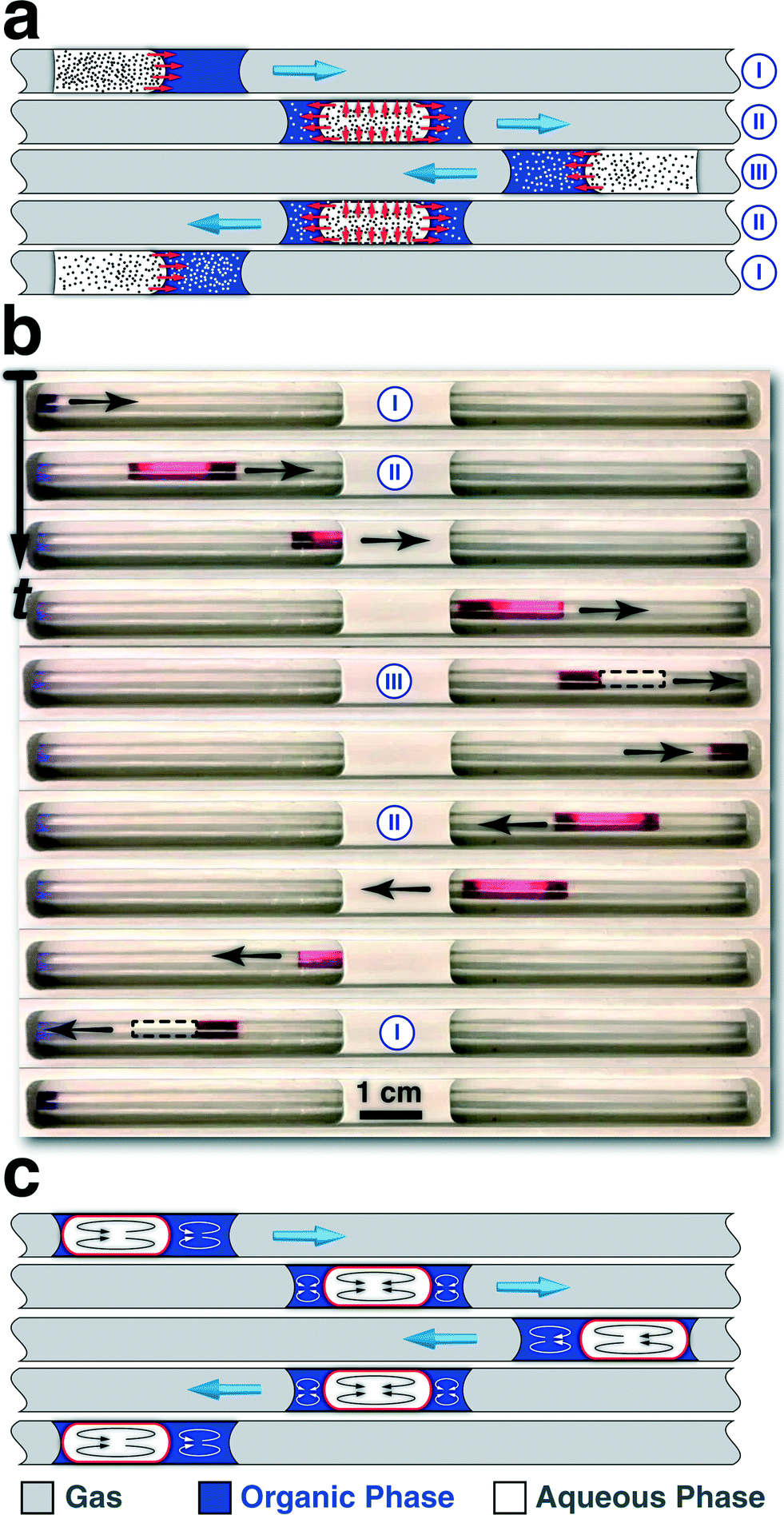 | ||
| Fig. 3 (a) Microscale mixing of two immiscible fluids using oscillatory multiphase flow strategy for in situ studies of intra-phase transport processes. (b) Snapshot time-series of the oscillatory motion of a bi-phasic slug (clear phase: DI water, 15 μL, red phase: 1-octanol labelled with Sudan red, 10 μL, gas: pressurized nitrogen) in a tubular FEP reactor, during one complete oscillation cycle. (c) Ideal microscale mixing of two immiscible fluids using oscillatory multiphase flow strategy for in-flow studies of bi-phasic interfacial catalytic reactions. The available interfacial area for the multiphase process is highlighted in red. Adopted with permission from the American Chemical Society, 2015 (b).69 | ||
As shown in Fig. 3a(I), in the initial bi-phasic slug configuration, both aqueous and organic phases are wetting the Teflon reactor. Upon starting the flow direction from left to right, the higher surface energy of the aqueous phase on the Teflon reactor, compared to the organic phase, results in a more facile motion of the aqueous segment. The unbalanced surface tension forces at the three-phase contact line in combination with the higher surface energy of the aqueous phase to the organic phase on the Teflon reactor, as well as the relatively low bi-phasic interfacial area results in engulfment of the aqueous phase within the organic phase. Upon full engulfment of the aqueous segment within the organic segment, the lubrication film (organic phase) surrounding the aqueous phase, results in a higher velocity for the engulfed aqueous phase (Fig. 3a(II) and b). The higher average velocity of the engulfed aqueous phase, compared to the wetting organic phase results in the relative displacement of the engulfed aqueous droplet from the back to the front of the organic segment, shown in the time-series of bright-field images of one complete oscillation cycle for a bi-phasic slug comprising DI water (clear phase) and 1-octanol (red phase).69 Ultimately, due the higher velocity of the engulfed phase, the aqueous droplet exits the wetting organic phase, wets the reactor wall, and the bi-phasic slug becomes two separate phases, both wetting the Teflon reactor (Fig. 3a(III) and b). The separation of two phases into two distinct segments (i.e., removal of the lubrication film), enables in situ absorption spectroscopy of each phase without interference of the other phase at each oscillation cycle.
In order to achieve maximum available interfacial area for bi-phasic catalytic reactions, ideally, the aqueous phase of the bi-phasic slug should be constantly engulfed within the organic phase throughout the experiment (Fig. 3c). Employing the scaling law relationship between the lubrication film thickness and the Capillary number of the aqueous phase,78,79 the minimum required oscillatory flow velocity, Uth, to achieve full engulfment of the aqueous phase within the organic phase during each oscillation cycle can be analytically predicted,64
It should also be noted that for processes operating at temperatures higher than room temperature, the temperature gradient between the oscillatory zone of the reactor and the remaining fluidic network might cause drifting of the train of droplets due to thermocapillarity motion80,81 or change in the density of the carrier fluid (gas) over the course of the experiment. Integration of an external optical feedback strategy (e.g., absorbance of a collimated light passing through a fluidic channel) can provide a reliable real-time information for automatic switching of the flow direction, thereby avoiding the drifting of the droplets from the heated zone of the flow reactor during the oscillation (Fig. 2b).
Applications of oscillatory multiphase flow platforms
(A) Chemistry
The oscillatory motion of an aqueous droplet was originally employed for mixing of two pre-formed droplets in a PDMS-based microfluidic channel (using air as the continuous phase), shown in Fig. 4a. The designed microfluidic platform was then utilized for in situ studies of an enzymatic reaction between L-glutamate oxidase and horseradish peroxidase through fluorescence microscopy.82 Computer-controlled microsyringe pumps with pre-defined infuse/withdraw volumes were employed for metering, sorting, merging, and oscillatory motion of a train of aqueous droplets containing different concentrations of L-glutamate. It was found that the activity of L-glutamate oxidase was highest in a pH range between 7 and 8 and further decrease or increase of pH gradually decrease its activity. This early oscillatory multiphase flow platform demonstrated the advantages of discretized residence/reaction times for process control using droplets in fluidic network. The on-demand control of the droplet position within the microchannel was similar to the precise level of droplet control obtained in electrowetting-based microfluidic devices83 (i.e., digital microfluidics), without the need for applying localized electronic potential.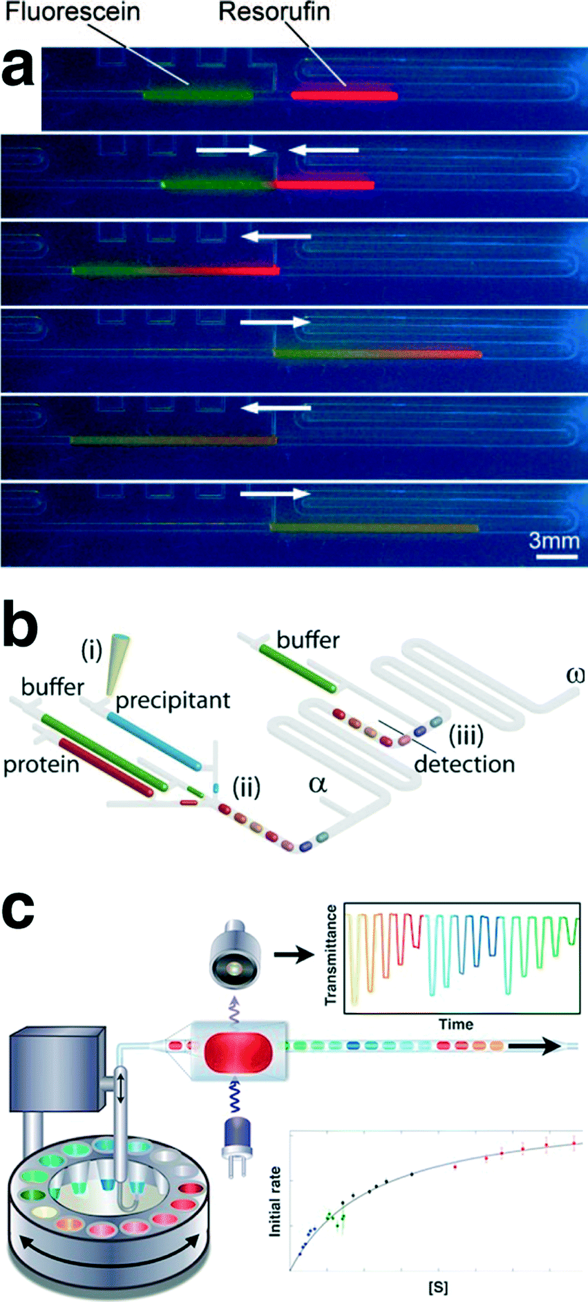 | ||
| Fig. 4 (a) Merging and mixing of two on-chip metered aqueous microdroplets using air-driven oscillatory motion characterized by fluorescence microscopy. (b) Schematic of the automated oscillatory multiphase flow strategy for continuous observation of crystallization process within oscillating droplets. (c) Schematic of the automated compartment-on-demand setup, developed for studies of enzyme kinetics and inhibition. Reproduced with permissions from the American Chemical Society, 2008 (a),82 and 2013 (c)71 and the Royal Society of Chemistry, 2012 (b).70 | ||
Dolega et al.70 developed a valve-based oscillatory multiphase flow, using paraffin oil as the carrier fluid, for on-chip screening and evaluation of proteins solubility diagrams (Fig. 4b), via an integrated spectral characterization tool (UV-vis absorption spectroscopy).70 A train of 30 aqueous droplets (960 nL per droplet) containing different concentration ratios of lysozyme and precipitant solutions were formed, and their corresponding UV absorption spectra were monitored every 15 min for an overall experiment time of 5 h. The automated oscillatory multiphase flow platform was then used to determine the lysozyme solubility diagrams as a function of concentrations of protein and precipitant. This work, for the first time, demonstrated the applicability of multiphase flow strategies for studies of long-term chemical processes (>30 min).
In a different multiphase oscillatory flow setup, a computer-controlled syringe pump integrated with a robotic arm and an in-line absorbance flow cell was used for on-demand formation and oscillation of microdroplets in a PTFE tubing from multiple aqueous reservoirs immersed in an inert continuous phase (Fig. 4c).71 The automated compartment on-demand platform was then utilized to conduct nanoliter assays in a high-throughput manner to obtain Michaelis–Menten parameters associated with hydrolysis of 4-nitrophenyl glucopyranoside by sweet almond b-glucosidase using a total sample volume of only 1.4 μL. In addition, the kinetic parameters of the inhibition of the enzymatic reaction of 1-deoxynojirimycin and conduritol B epoxide were measured within 20 min. This work further demonstrated the application of oscillatory multiphase flow strategy for obtaining a large data set of the process of interest accommodated within a short reactor length (volume).
In a different study, two 3-port electromagnetic valves connected to two constant pressure sources of the dispersed phase (gas) were employed for alternating the pressure gradient applied across a train of droplets within a hybrid silicon-Pyrex microfluidic device.57 Microscale mixing of two miscible fluids within a liquid segment enabled by the oscillatory multiphase flow format was characterized using fluorescence microscopy. In addition, integrating on-chip UV-vis absorption spectroscopy with oscillatory flow allowed long-term studies of the size and shape evolution of metallic nanoparticles (gold nanorods). The transverse and longitudinal surface plasmon resonance absorbance peaks associated with diameter and length of the gold nanorods, respectively, were monitored for on-line evaluation of the shape evolution kinetics over the course of a 5 h chemical etching process.
Recently, a syringe-pump based oscillatory flow strategy using pressurized inert gas as the carrier phase in combination with a computer-controlled liquid handler was developed for in-flow studies of chemical processes comprising immiscible fluids (Fig. 5a and b).64,69 Integration of in-line analytical tools such as UV-vis absorption spectroscopy, HPLC, and mass spectroscopy units with the developed multiphase oscillatory flow strategy enabled screening, library development, and optimization of the physical/chemical process of interest. The developed oscillatory multiphase flow strategy was then applied for in-flow studies of bi-phasic Suzuki–Miyaura and Buchwald–Hartwig cross coupling reactions64 (Fig. 5a), as well as automated measurement and screening of water–octanol partition coefficient of pharmaceutical compounds69 (Fig. 5b). The increase in the available interfacial area, owing to the complete engulfment of the aqueous droplet within the organic phase (Fig. 5a), addressed the mass transfer limitation of continuous multiphase flow strategies for studies of bi-phasic C–C and C–N cross coupling reactions, and reproduced the same reaction yields as a batch reactor. As explained before, in the oscillatory micromixing of two immiscible fluids (Fig. 3), the higher surface energy of the aqueous phase on the Teflon reactor, compared to the organic phase, results in a more facile motion of the aqueous phase and full engulfment of the aqueous droplet within the wetting organic segment. The presence of the organic phase lubrication film surrounding the aqueous phase, results in a higher velocity for the engulfed aqueous phase (Fig. 5b), and displacement of the engulfed aqueous droplet from the back to the front of the wetting organic phase.
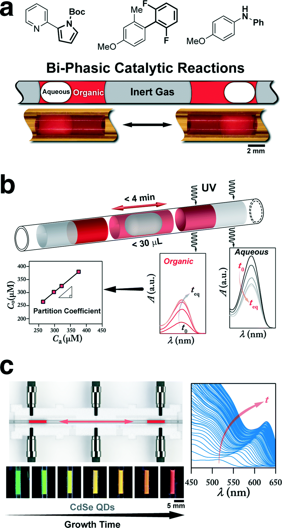 | ||
| Fig. 5 (a) Three-phase oscillatory flow reactor for in-flow studies of bi-phasic interfacial catalytic reactions (e.g., C–C and C–N cross-coupling reactions). (b) Oscillatory multiphase flow strategy integrated with in situ UV absorption spectroscopy for fast and efficient water–octanol partition coefficient measurement and screening of organic compounds. The continuous phase is pressurized nitrogen (10 psig). (c) Oscillatory microprocessor for in situ characterization of the growth of semiconductor nanocrystals at the synthesis temperature. Reprinted with permission from the Royal Society of Chemistry, 2015 (a)64 and the American Chemical Society, 2015 (b)69 and (c).65 | ||
On the other hand, use of an integrated optical feedback strategy (through two fiber-coupled LEDs and photodetectors) avoided drifting and ensured the pre-formed droplet was trapped within the heated region of the oscillatory flow reactor for the intended processing time. Combination of the optical feedback with an in situ UV-vis absorption spectroscopy technique enabled automated water–octanol partition coefficient measurement of pharmaceutical compounds within 4 min per drug at the physiologically relevant temperature of 37 °C, which is otherwise time-and labour-intensive to obtain using conventional batch scale techniques (e.g., shake-flask method).69
A similar oscillatory flow platform was used to study growth of II–VI and III–V semiconductor nanocrystals at relatively high temperatures (160–220 °C).65 The temporal in situ measurements of absorption spectra for the semiconductor nanocrystals at the synthesis temperature, shown in Fig. 5c, provided insights into the effect of synthesis temperature on growth kinetics.
(B) Biology
In addition to physical and chemical processes, the multiphase oscillatory flow technique has enabled long-term studies of biological processes. A combination of a constantly infusing syringe pump and a computer-controlled electric valve was implemented in a liquid–liquid oscillatory multiphase flow platform for high-throughput long-term studies of the dynamics of microbial population growth.66 The population growth was monitored over multiple generations in >1000 droplets (∽100 nL per droplet), shown in Fig. 6a and b.66 The automated millifluidic setup was then used in systematic studies of the effect of medium composition on the growth rate of microbial population. In addition, the doubling times of monoclonal populations of E. coli were automatically determined through monitoring minimal inhibitory concentration of an antibiotic cefotaxime (CTX) using fluorescence microscopy (Fig. 6b). A similar oscillatory flow platform was also employed to study the effect of cell-to-cell heterogeneity on growth dynamics of isogenic cell populations of Chlamydomonas reinhardtii over a period of one week (Fig. 6c). The millifluidic setup was capable of sorting and collecting the droplets of interest containing viable cells at the end of the experiment for further off-line characterization.68 To avoid cross-contamination between the adjacent droplets over the course of a 100 h experiment, an inert droplet (air) was inserted between each two consecutive aqueous droplets containing the microalgae cells dispersed in tris-acetate–phosphate (TAP, growth solution). The oscillatory motion of droplets, in addition to ensuring homogenous distribution of dissolved oxygen and carbon dioxide within droplets, prevented the settling and aggregation of algal cells through constant stirring and internal recirculation. Fig. 6c shows homogenous growth dynamics of Chlamydomonas cells from an initial population size of ∽100 cells per droplet, obtained via fluorescence microscopy. These work demonstrated another avenue for utilization of oscillatory multiphase flow strategy in long-term studies of biological processes as a high-throughput nanoliter assay. In another microbiology study, Jakiela et al.67 developed a valve-based oscillatory flow platform for manipulation and continuous monitoring of population growth of bacteria in microdroplet chemostats, through in situ spectral characterization (Fig. 6d).67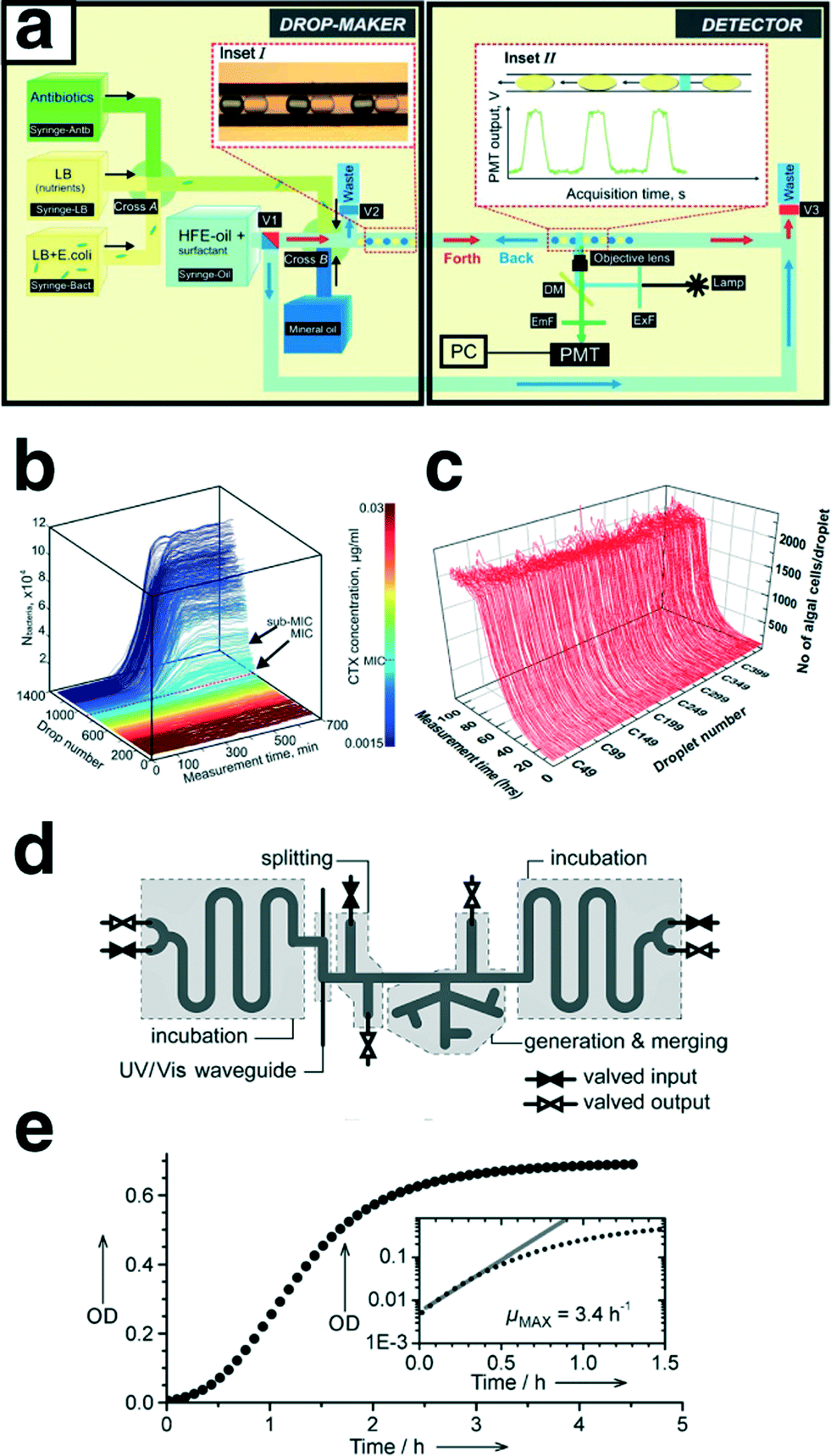 | ||
| Fig. 6 (a) Automated millifluidic platform developed for continuous monitoring of the growth dynamics of microbial populations over multiple generations; the setup includes droplet generation, incubation, and characterization via oscillatory motion of the pre-formed droplets. (b) 3-D growth curves of the bacterial populations, grown in the gradient of antibiotic cefotaxime (CTX) concentrations. (c) 3-D growth curves of 450 microdroplets with initial inoculation population size of ∽100 unicellular microalgae C. reinhardtii cells per droplet. (d) Schematic of the designed and microfabricated microfluidic device for long-term continuous observation of population growth of bacteria. (e) Growth curve of E. coli ATCC 25992 cells obtained using the microdroplet-based chemostat shown in (d). Reproduced with permission from the Royal Society of Chemistry, 2011 (a, b),66 from Public Library of Science, 2015 (c)68 and from Wiley-VCH, 2013 (d, e).67 | ||
The automated microdroplet chemostat setup allowed on-demand formation of microdroplets containing E. coli cells and growth factors. The on-chip formed microdroplet chemostats (164 droplets) were then cycled back and forth for incubation and continuous population monitoring (Fig. 6e).
Discretizing the motion of microdroplets through computer-controlled electromagnetic valves enabled on-demand addition (infusion) of chemical factors to the microdroplet chemostats over the course of the experiment. The automated micro-chemostat platform demonstrated a multi-step operation (i.e., on-demand composition tuning of the microdroplets) enabled through oscillatory flow strategy. The ability to constantly provide fresh nutrients to microdroplets extended the long-term parallel studies of the effect of varying chemical factors on the dynamics of microbial populations to over 100 h.
Summary and outlook
Oscillatory multiphase flow techniques over the past couple of years have demonstrated the possibility of adaptation of microscale flow technologies for studies of long-term (>30 min) physical, chemical, and biological processes by addressing the residence time limitation associated with continuous multiphase flow strategies. Moreover, the simple back-and-forth motion of droplets has enabled single-point temporal characterization of the process of interest within the microreaction vessel (i.e., microdroplet) through in situ UV-vis spectroscopy at the relevant pressures and temperatures, without the need for manual sampling or formation of single droplet per reaction time. A single microdroplet could be used for kinetic studies of the (bio)chemical reaction at a defined temperature, pressure, and concentration. In addition, multiplexed oscillatory multiphase flow platforms could be envisioned for high-throughput parameter screening of gas/liquid–liquid reactions in a numbered up reactor configuration, operating at different temperatures to surpass conventional batch scale and well-plate based high-throughput screening strategies operated at a constant temperature.The oscillatory multiphase flow strategy has the potential to become a versatile and efficient discovery and characterization tool in long-term studies of (bio)chemical processes, but a number of important questions remain to be addressed.
The oscillatory flow approach would greatly benefit from further hydrodynamic characterization of single/multi-phase flow formats. A comprehensive guideline suggesting the reactor material (based on the desired surface energy, and flow behaviour) for the target application would accelerate the future development of the technology. Furthermore, reducing the number of custom-designed parts and utilizing commercially available off-the-shelf components (e.g., tubing and fluidic connectors instead of microfabricated reactors) would facilitate further adaptation of the oscillatory multiphase flow setup in chemistry and biology research labs. Additionally, providing detailed carry-over characterization, and potential experimental strategies (e.g., washing protocols) to significantly reduce (or completely remove) the effect of droplets carry-over on the measured results would be beneficial.
In addition to the case studies highlighted in this frontier article, as shown in Fig. 7, we envision that the modular and easy to assemble oscillatory multiphase flow technique could potentially be applied towards better fundamental understanding of (a) nanomaterials of future for energy, biology, and display applications (e.g., organometal halide perovskite nanocrystals,84 and rare earth upconversion nanocrystals85); (b) photocatalytic reactions such as visible light photo-redox catalysis86 and photochemical reduction of carbon dioxide; (c) solvent extraction kinetics and recovery efficiency of the recently developed CO2-triggered switchable solvents (e.g., nitrogenous bases), as green alternatives to volatile and toxic organic solvents.87,88
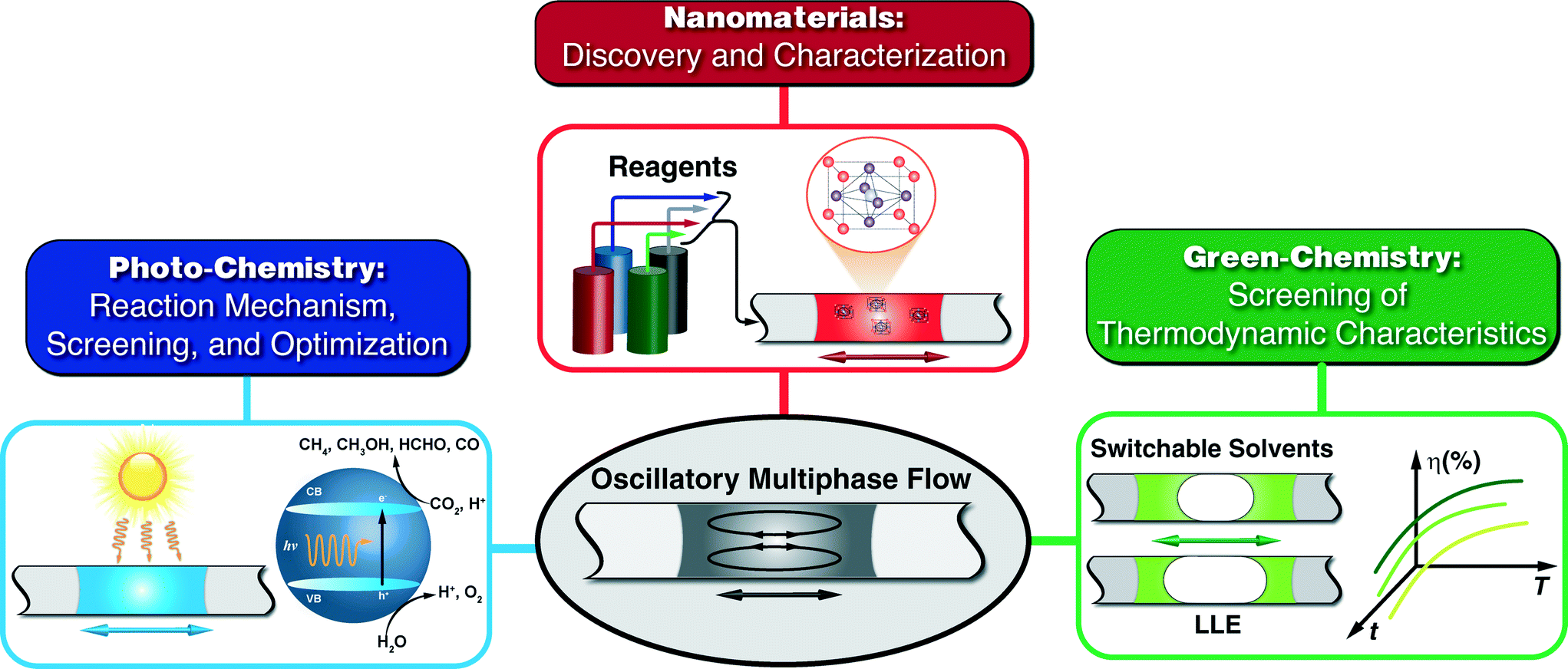 | ||
| Fig. 7 Proposed future opportunities of oscillatory multiphase flow strategy (a) as a discovery and characterization platform for targeted development of the next generation of semiconductor/metallic nanomaterials in solar cells, displays, and biological imaging; (b) as an experimental strategy for fundamental studies of photo-chemical CO2 reduction and visible-light photo-redox catalysis processes; (c) as a high-throughput screening platform for thermodynamic studies of CO2-triggered switchable solvents (switchable ionic strength, polarity, and hydrophilicity). | ||
In summary, continuous multiphase flow has significantly improved the accuracy and throughput of conventional discovery and screening methodologies in chemistry and biology. Capitalizing on the separation of characteristic mixing and residence time scales, oscillatory multiphase flow technology further expands and complements the addressable parameter space associated with continuous multiphase flow approaches. We hope this frontier article will further facilitate the adaptation of oscillatory microscale flow strategies in pharma, energy, and healthcare sectors as a reliable and an efficient discovery and exploratory platform.
Acknowledgements
M. A. gratefully acknowledges financial support from an NSERC Postdoctoral Fellowship.References
- G. M. Whitesides, Nature, 2006, 442, 368–373 CrossRef CAS PubMed.
- A. J. deMello, Nature, 2006, 442, 394–402 CrossRef CAS PubMed.
- G. M. Whitesides, Nat. Biotechnol., 2003, 21, 1161–1165 CrossRef CAS PubMed.
- J. El-Ali, P. K. Sorger and K. F. Jensen, Nature, 2006, 442, 403–411 CrossRef CAS PubMed.
- T. M. Squires and S. R. Quake, Rev. Mod. Phys., 2005, 77, 977–1026 CrossRef CAS.
- K. S. Elvira, X. C. I. Solvas, R. C. R. Wootton and A. J. deMello, Nat. Chem., 2013, 5, 905–915 CrossRef CAS PubMed.
- K. F. Jensen, Chem. Eng. Sci., 2001, 56, 293–303 CrossRef CAS.
- R. L. Hartman, J. P. McMullen and K. F. Jensen, Angew. Chem., Int. Ed., 2011, 50, 7502–7519 CrossRef CAS PubMed.
- Y. Kikutani and T. Kitamori, Macromol. Rapid Commun., 2004, 25, 158–168 CrossRef CAS.
- S. L. Poe, M. A. Cummings, M. P. Haaf and D. T. McQuade, Angew. Chem., Int. Ed., 2006, 45, 1544–1548 CrossRef CAS PubMed.
- H. A. Stone and S. Kim, AIChE J., 2001, 47, 1250–1254 CrossRef CAS.
- S. Marre and K. F. Jensen, Chem. Soc. Rev., 2010, 39, 1183–1202 RSC.
- H. Song, D. L. Chen and R. F. Ismagilov, Angew. Chem., Int. Ed., 2006, 45, 7336–7356 CrossRef CAS PubMed.
- S.-Y. Teh, R. Lin, L.-H. Hung and A. P. Lee, Lab Chip, 2008, 8, 198–220 RSC.
- A. Gunther and K. F. Jensen, Lab Chip, 2006, 6, 1487–1503 RSC.
- M. T. Guo, A. Rotem, J. A. Heyman and D. A. Weitz, Lab Chip, 2012, 12, 2146–2155 RSC.
- J. J. Agresti, E. Antipov, A. R. Abate, K. Ahn, A. C. Rowat, J.-C. Baret, M. Marquez, A. M. Klibanov, A. D. Griffiths and D. A. Weitz, Proc. Natl. Acad. Sci. U. S. A., 2010, 107, 4004–4009 CrossRef CAS PubMed.
- B. L. Wang, A. Ghaderi, H. Zhou, J. Agresti, D. A. Weitz, G. R. Fink and G. Stephanopoulos, Nat. Biotechnol., 2014, 32, 473–478 CrossRef CAS PubMed.
- E. Brouzes, M. Medkova, N. Savenelli, D. Marran, M. Twardowski, J. B. Hutchison, J. M. Rothberg, D. R. Link, N. Perrimon and M. L. Samuels, Proc. Natl. Acad. Sci. U. S. A., 2009, 106, 14195–14200 CrossRef CAS PubMed.
- C. B. Rohde, F. Zeng, R. Gonzalez-Rubio, M. Angel and M. F. Yanik, Proc. Natl. Acad. Sci. U. S. A., 2007, 104, 13891–13895 CrossRef CAS PubMed.
- M. Chabert and J.-L. Viovy, Proc. Natl. Acad. Sci. U. S. A., 2008, 105, 3191–3196 CrossRef CAS PubMed.
- L. Li, D. Mustafi, Q. Fu, V. Tereshko, D. L. Chen, J. D. Tice and R. F. Ismagilov, Proc. Natl. Acad. Sci. U. S. A., 2006, 103, 19243–19248 CrossRef CAS PubMed.
- L. Li and R. F. Ismagilov, Annu. Rev. Biophys., 2010, 39, 139–158 CrossRef CAS PubMed.
- A. R. Abate, T. Hung, P. Mary, J. J. Agresti and D. A. Weitz, Proc. Natl. Acad. Sci. U. S. A., 2010, 107, 19163–19166 CrossRef CAS PubMed.
- M. Srisa-Art, A. J. deMello and J. B. Edel, Anal. Chem., 2007, 79, 6682–6689 CrossRef CAS PubMed.
- J.-W. Choi, D.-K. Kang, H. Park, A. J. deMello and S.-I. Chang, Anal. Chem., 2012, 84, 3849–3854 CrossRef CAS PubMed.
- S. Cho, D.-K. Kang, S. Sim, F. Geier, J.-Y. Kim, X. Niu, J. B. Edel, S.-I. Chang, R. C. R. Wootton, K. S. Elvira and A. J. deMello, Anal. Chem., 2013, 85, 8866–8872 CrossRef CAS PubMed.
- M. Srisa-Art, E. C. Dyson, A. J. deMello and J. B. Edel, Anal. Chem., 2008, 80, 7063–7067 CrossRef CAS PubMed.
- K. Churski, P. Korczyk and P. Garstecki, Lab Chip, 2010, 10, 816–818 RSC.
- K. Churski, T. S. Kaminski, S. Jakiela, W. Kamysz, W. Baranska-Rybak, D. B. Weibel and P. Garstecki, Lab Chip, 2012, 12, 1629–1637 RSC.
- T. S. Kaminski, S. Jakiela, M. A. Czekalska, W. Postek and P. Garstecki, Lab Chip, 2012, 12, 3995–4002 RSC.
- J. Guzowski, P. M. Korczyk, S. Jakiela and P. Garstecki, Lab Chip, 2011, 11, 3593–3595 RSC.
- D. Chen, W. Du, Y. Liu, W. Liu, A. Kuznetsov, F. E. Mendez, L. H. Philipson and R. F. Ismagilov, Proc. Natl. Acad. Sci. U. S. A., 2008, 105, 16843–16848 CrossRef CAS PubMed.
- B. J. Reizman and K. F. Jensen, Chem. Commun., 2015, 51, 13290–13293 RSC.
- M. Abolhasani, M. Singh, E. Kumacheva and A. Gunther, Lab Chip, 2012, 12, 1611–1618 RSC.
- D. Voicu, M. Abolhasani, R. Choueiri, G. Lestari, C. Seiler, G. Menard, J. Greener, A. Guenther, D. W. Stephan and E. Kumacheva, J. Am. Chem. Soc., 2014, 136, 3875–3880 CrossRef CAS PubMed.
- M. Abolhasani, A. Günther and E. Kumacheva, Angew. Chem., Int. Ed., 2014, 53, 7992–8002 CrossRef CAS PubMed.
- G. Lestari, M. Abolhasani, D. Bennett, P. Chase, A. Günther and E. Kumacheva, J. Am. Chem. Soc., 2014, 136, 11972–11979 CrossRef CAS PubMed.
- S. G. R. Lefortier, P. J. Hamersma, A. Bardow and M. T. Kreutzer, Lab Chip, 2012, 12, 3387–3391 RSC.
- R. Sun and T. Cubaud, Lab Chip, 2011, 11, 2924–2928 RSC.
- G. Niu, A. Ruditskiy, M. Vara and Y. Xia, Chem. Soc. Rev., 2015, 44, 5806–5820 RSC.
- L. Zhang, G. Niu, N. Lu, J. Wang, L. Tong, L. Wang, M. J. Kim and Y. Xia, Nano Lett., 2014, 14, 6626–6631 CrossRef CAS PubMed.
- I. Lignos, L. Protesescu, S. Stavrakis, L. Piveteau, M. J. Speirs, M. A. Loi, M. V. Kovalenko and A. J. deMello, Chem. Mater., 2014, 26, 2975–2982 CrossRef CAS.
- I. Lignos, S. Stavrakis, G. Nedelcu, L. Protesescu, A. J. deMello and M. V. Kovalenko, Nano Lett., 2016, 16, 1869–1877 CrossRef CAS PubMed.
- A. M. Nightingale, T. W. Phillips, J. H. Bannock and J. C. de Mello, Nat. Commun., 2014, 5, 3777 CAS.
- A. R. C. Duarte, B. Ünal, J. F. Mano, R. L. Reis and K. F. Jensen, Langmuir, 2014, 30, 12391–12399 CrossRef CAS PubMed.
- S. Xu, Z. Nie, M. Seo, P. Lewis, E. Kumacheva, H. A. Stone, P. Garstecki, D. B. Weibel, I. Gitlin and G. M. Whitesides, Angew. Chem., Int. Ed., 2005, 44, 724–728 CrossRef CAS PubMed.
- Z. Nie, W. Li, M. Seo, S. Xu and E. Kumacheva, J. Am. Chem. Soc., 2006, 128, 9408–9412 CrossRef CAS PubMed.
- S.-K. Lee, J. Baek and K. F. Jensen, Langmuir, 2014, 30, 2216–2222 CrossRef CAS PubMed.
- V. Sebastian, C. D. Smith and K. F. Jensen, Nanoscale, 2016, 8, 7534–7543 RSC.
- S. Duraiswamy and S. A. Khan, Small, 2009, 5, 2828–2834 CrossRef CAS PubMed.
- S. A. Khan, A. Günther, M. A. Schmidt and K. F. Jensen, Langmuir, 2004, 20, 8604–8611 CrossRef CAS PubMed.
- B. K. H. Yen, A. Günther, M. A. Schmidt, K. F. Jensen and M. G. Bawendi, Angew. Chem., 2005, 117, 5583–5587 CrossRef.
- A. B. Theberge, F. Courtois, Y. Schaerli, M. Fischlechner, C. Abell, F. Hollfelder and W. T. S. Huck, Angew. Chem., Int. Ed., 2010, 49, 5846–5868 CrossRef CAS PubMed.
- A. Huebner, S. Sharma, M. Srisa-Art, F. Hollfelder, J. B. Edel and A. J. deMello, Lab Chip, 2008, 8, 1244–1254 RSC.
- D. T. Chiu, R. M. Lorenz and G. D. M. Jeffries, Anal. Chem., 2009, 81, 5111–5118 CrossRef CAS PubMed.
- M. Abolhasani, A. Oskooei, A. Klinkova, E. Kumacheva and A. Gunther, Lab Chip, 2014, 14, 2309–2318 RSC.
- V. S. Chakravarthy and J. M. Ottino, Chem. Eng. Sci., 1996, 51, 3613–3622 CrossRef CAS.
- W.-L. Chien, H. Rising and J. M. Ottino, J. Fluid Mech., 1986, 170, 355–377 CrossRef CAS.
- F. Shen, W. Du, J. E. Kreutz, A. Fok and R. F. Ismagilov, Lab Chip, 2010, 10, 2666–2672 RSC.
- D. E. Cohen, T. Schneider, M. Wang and D. T. Chiu, Anal. Chem., 2010, 82, 5707–5717 CrossRef CAS PubMed.
- Y. Wang, Y. Li, H. Thérien-Aubin, J. Ma, P. W. Zandstra and E. Kumacheva, Biomicrofluidics, 2016, 10, 014110 CrossRef PubMed.
- C. J. Gerdts, V. Tereshko, M. K. Yadav, I. Dementieva, F. Collart, A. Joachimiak, R. C. Stevens, P. Kuhn, A. Kossiakoff and R. F. Ismagilov, Angew. Chem., Int. Ed., 2006, 45, 8156–8160 CrossRef CAS PubMed.
- M. Abolhasani, N. C. Bruno and K. F. Jensen, Chem. Commun., 2015, 51, 8916–8919 RSC.
- M. Abolhasani, C. W. Coley, L. Xie, O. Chen, M. G. Bawendi and K. F. Jensen, Chem. Mater., 2015, 27, 6131–6138 CrossRef CAS.
- L. Baraban, F. Bertholle, M. L. M. Salverda, N. Bremond, P. Panizza, J. Baudry, J. A. G. M. de Visser and J. Bibette, Lab Chip, 2011, 11, 4057–4062 RSC.
- S. Jakiela, T. S. Kaminski, O. Cybulski, D. B. Weibel and P. Garstecki, Angew. Chem., Int. Ed., 2013, 52, 8908–8911 CrossRef CAS PubMed.
- S. P. Damodaran, S. Eberhard, L. Boitard, J. G. Rodriguez, Y. Wang, N. Bremond, J. Baudry, J. Bibette and F.-A. Wollman, PLoS One, 2015, 10, e0118987 Search PubMed.
- M. Abolhasani, C. W. Coley and K. F. Jensen, Anal. Chem., 2015, 87, 11130–11136 CrossRef CAS PubMed.
- M. E. Dolega, S. Jakiela, M. Razew, A. Rakszewska, O. Cybulski and P. Garstecki, Lab Chip, 2012, 12, 4022–4025 RSC.
- F. Gielen, L. van Vliet, B. T. Koprowski, S. R. A. Devenish, M. Fischlechner, J. B. Edel, X. Niu, A. J. deMello and F. Hollfelder, Anal. Chem., 2013, 85, 4761–4769 CrossRef CAS PubMed.
- S. Jakiela, P. M. Korczyk, S. Makulska, O. Cybulski and P. Garstecki, Phys. Rev. Lett., 2012, 108, 134501 CrossRef PubMed.
- C. N. Baroud, F. Gallaire and R. Dangla, Lab Chip, 2010, 10, 2032–2045 RSC.
- H. Kinoshita, S. Kaneda, T. Fujii and M. Oshima, Lab Chip, 2007, 7, 338–346 RSC.
- T. C. Thulasidas, M. A. Abraham and R. L. Cerro, Chem. Eng. Sci., 1995, 50, 183–199 CrossRef CAS.
- J. Bico and D. Queré, J. Fluid Mech., 2002, 467, 101–127 CAS.
- D. L. Chen, L. Li, S. Reyes, D. N. Adamson and R. F. Ismagilov, Langmuir, 2007, 23, 2255–2260 CrossRef CAS PubMed.
- L. W. Schwartz, H. M. Princen and A. D. Kiss, J. Fluid Mech., 1986, 172, 259–275 CrossRef CAS.
- F. P. Bretherton, J. Fluid Mech., 1961, 10, 166–188 CrossRef.
- V. G. Levich, Physicochemical hydrodynamics, Prentice-Hall, Englewood Cliffs, 1962 Search PubMed.
- F. Brochard, Langmuir, 1989, 5, 432–438 CrossRef CAS.
- F. Sassa, J. Fukuda and H. Suzuki, Anal. Chem., 2008, 80, 6206–6213 CrossRef CAS PubMed.
- K. Choi, A. H. C. Ng, R. Fobel and A. R. Wheeler, Annu. Rev. Anal. Chem., 2012, 5, 413–440 CrossRef CAS PubMed.
- L. Protesescu, S. Yakunin, M. I. Bodnarchuk, F. Krieg, R. Caputo, C. H. Hendon, R. X. Yang, A. Walsh and M. V. Kovalenko, Nano Lett., 2015, 15, 3692–3696 CrossRef CAS PubMed.
- E. M. Chan, Chem. Soc. Rev., 2015, 44, 1653–1679 RSC.
- J. M. R. Narayanam and C. R. J. Stephenson, Chem. Soc. Rev., 2011, 40, 102–113 RSC.
- P. G. Jessop, S. M. Mercer and D. J. Heldebrant, Energy Environ. Sci., 2012, 5, 7240–7253 CAS.
- G. Lestari, A. Salari, M. Abolhasani and E. Kumacheva, Lab Chip, 2016, 16, 2710–2718 RSC.
| This journal is © The Royal Society of Chemistry 2016 |