Digital microfluidics with a magnetically actuated floating liquid marble
Mei Kum
Khaw
a,
Chin Hong
Ooi
a,
Faisal
Mohd-Yasin
a,
Raja
Vadivelu
b,
James St
John
b and
Nam-Trung
Nguyen
 *a
*a
aQueensland Micro- and Nanotechnology Centre, Nathan Campus, Griffith University, 170 Kessels Road, QLD 4111, Australia. E-mail: nam-trung.nguyen@griffith.edu.au
bEskitis Institute for Drug Discovery, Griffith University, Brisbane, QLD 4111, Australia
First published on 5th May 2016
Abstract
Controlled actuation of a floating liquid marble, a liquid droplet coated with hydrophobic particles floating on another liquid surface, is a potential digital microfluidics platform for the transport of aqueous solution with minimal volume loss. This paper reports our recent investigation on the magnetic actuation of floating liquid marbles filled with magnetic particles. The magnetic force and frictional force acting on the floating liquid marble determine the horizontal movement of the marble. We varied the magnetic flux density, flux density gradient, concentration of magnetic particles and speed of the marble to elucidate the relationship between the acting forces. We subsequently determined the suitable operating conditions for the actuation and derived the scaling laws for the actuation parameters.
1. Introduction
Digital microfluidics is an emerging microfluidic technology. In conventional digital microfluidics, droplets with volume on the order of picoliters to microliters can be manipulated individually using the electrowetting phenomenon using an external electric field.1,2 Alternatively, forces induced by a magnetic field or the Marangoni effect due to the surface tension gradient can be used as actuation schemes for digital microfluidics.3,4A liquid marble is typically an aqueous solution encapsulated by a coating of hydrophobic powder. The powder is attracted to the liquid–air interface and forms a coating that isolates the liquid in a marble from the external surface it is resting on by an air layer.5,6 The surface can be a solid surface or the free surface of another aqueous solution. On a solid surface, a liquid marble can roll or slide around without wetting the surface.7 On an aqueous free surface, the liquid marble floats and slides with minimum friction.8–10
The non-wetting feature of liquid marbles allows the transport of liquid without significant volume loss and energy loss due to the low friction with the platform surface. The useful properties of a liquid marble have been detailed in several excellent review papers.11–14 A recent review by Ooi and Nguyen15 demonstrated that a liquid marble can be actuated through electrostatic force,16 magnetic force,17–19 gravitational force,11 pressure gradient20 and chemical schemes.21–23 Therefore, the manipulation of liquid marbles is potentially useful for digital microfluidics. In comparison with microchannel-based microfluidics, manipulation of discrete droplets without being confined in a closed channel allows for great flexibility and versatile applications.
A liquid marble also has a lower evaporation rate as compared to a non-coated free droplet.24,25 Although the gas exchange within the liquid marble and surrounding environment cannot be avoided, the volume of a liquid marble can be maintained by changing the humidity and temperature of its surrounding. This characteristic makes liquid marbles suitable to serve as a cell culture platform26–29 and for sensing applications.30,31 Vadivelu et al. used a floating liquid marble as a bioreactor for growing three-dimensional cell spheroids.27 The floating liquid marble allows the cells to freely associate and interact to produce uniform sized spheroids. The quality of the spheroids depends on the internal mixing process, which in turn depends on the motion of the marble over the surface of the supporting liquid. Moving the marble around would induce internal flow and mixing. Ooi et al. reported the kinematics and dynamics of a floating self-propelling liquid marble containing ethanol.3 The self-driven movement is caused by the Marangoni solutocapillary effect, which is difficult to control and depends on the availability of ethanol acting as the fuel inside the marble. Our motivation for the present work is the development of a controllable magnetic actuation scheme for the floating liquid marble leading to a practical digital microfluidics platform.
Recent works already described the kinematics and dynamics of magnetically actuated sessile droplets on a solid surface.32–35 Nguyen et al. investigated the sliding motion of sessile water-based non-reactive ferrofluid droplets on hydrophobic planar surfaces using a moving external magnet.35 This work provided the critical velocities of the actuated droplets with different magnetic flux densities induced by different permanent magnets. Furthermore, Koh et al. demonstrated the use of magnetically actuated ferrofluid droplets as actuators for the key functions in digital microfluidics such as merging and mixing of other non-magnetic liquid droplets.34 The drawback of this work was that the whole droplet should be magnetic, for example using ferrofluid, such that the magnetic force is large enough to overcome the friction with the solid surface. Ferrofluid is not compatible with biological applications such as cell culture, thus using a minute number of magnetic particles mixed in the liquid could provide sufficient magnetic force for actuation and at the same time does not affect the other components in the liquid. Magnetic force has been previously used to manipulate liquid marbles. Zhao et al. demonstrated that liquid can be extracted or added to a liquid marble coated with hydrophobic magnetic particles enabling the liquid marble to be used in a micro reactor and micro mixer.17 Liquid marbles coated with magnetic powder can have their shells “opened” and “closed”17–19 or even moved around18,36,37 using a permanent magnet. Actuation with a small number of larger magnetic particles in a droplet would not work because the small magnetic force cannot overcome the friction force or would be too large so that the particle is removed from the droplet. The solution for reducing the friction is to float the liquid marble on a liquid surface and then drag it with a minute number of magnetic particles and an external magnet.
The objective of our present work is to study the sliding motion of a magnetically actuated floating marble. We experimentally evaluate the parameters that affect the motion of a floating liquid marble in terms of displacement and velocity such as the volume concentration of magnetic particles, the speed and the flux density of the driving permanent magnet. With these data, we can then determine the suitable operating conditions for the actuation as well as the critical points where the liquid marble no longer follows the permanent magnet. The scaling relationship of the operation parameters can be compared with the counterparts of a sessile droplet moving on a hydrophobic surface.
2. Materials and methods
Experimental setup
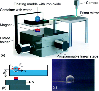
Fig. 1 depicts our experimental platform, which consists of a holder made of polymethyl methacrylate (PMMA,) a container made of polystyrene, a permanent magnet and a programmable x–y stage. The holder is made of 4.5 mm thick PMMA plates and has a slit to hold a 1.5 mm thick PMMA plate for positioning the 10 × 10 cm polystyrene container. The water levels to be filled were marked with a permanent marker on the polystyrene container. A cubic permanent magnet (Neodymium, 3.12 × 3.12 × 3.12 mm) was fixed on a programmable x–y stage. The permanent magnet was placed below the container as a tool to move the floating marble. This magnet was positioned at distances of 6 mm, 8 mm, 10 mm, 12 mm, 14 mm and 16 mm from the water level markings. We used a vernier caliper to accurately adjust the distance, taking into account the combined thickness of 2.5 mm of the PMMA plate and the polystyrene container.The x–y stage was a motorized linear actuator (Zaber Technologies T-LS28M) with built-in controllers. The actuator has a travel range of 28 mm, a maximum speed of 6.5 mm s−1 and a minimum speed of 0.93 μm s−1. The linear motion of the actuator was controlled by the Zaber Console software. Codes were programmed to define the velocity of the actuator. The actuator was linked to a personal computer (PC) through an RS-232 port. The actuator allowed a programmable and smooth motion of the permanent magnet in both directions.
The experimental setup facilitates video capturing of the moving liquid marble. The video of the floating marble was recorded and further processed to examine the motion. For this purpose, a 45° prism mirror was placed under the camera to capture the side view of the floating marble without blocking the x–y stage and the container. The floating marble was backlit with a light source to create a large contrast between the marble and its surrounding. The images were captured by a USB camera (Edmund Optics Inc, Singapore) with an adjustable lens (AF Micro Nikkor 60 mm f/2.8D). The camera software (uEye cockpit, IDS, Germany) was set to record the motion with 30 frames per second (fps) in a single movie file. In the subsequent image-processing step, the frames were separated and evaluated individually using ImageJ (National Institutes of Health, USA) and a custom-written program in Matlab (Mathworks, USA), to obtain a quantitative assessment of the motion (displacement, velocity and acceleration) of the floating marble.
In the experiments, deionised water was filled into the container till it reached the first marked level, representing 6 mm distance from the magnet. A 5 μL magnetised liquid marble was carefully placed into the container. The floating marble automatically aligned itself to the centre of the permanent magnet. The magnet was programmed to move back and forth with a pre-set amplitude of 4.96 mm and 9 speeds ranging from 0.465 mm s−1 to 4.19 mm s−1. Next, 0.2 ml of deionised water was drawn with a syringe and added into the container corresponding to an increase of 2 mm in the water level. The experiment was repeated for the different water levels. The motions of the floating marble are recorded and analysed for each water level or marble–magnet distance and its corresponding speed. The Matlab program then processed the video and measured and tracked the centroid of the floating marble as it moved back and forth with the permanent magnet.
Preparation of a floating marble for magnetic actuation
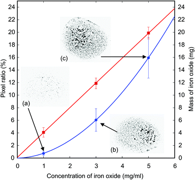
The liquid marble was formed by mixing deionised water with iron oxide powder (Sigma-Aldrich, Iron II/III oxide). Magnetite particles are spherical with a diameter of less than 5 μm and a density of approximately 4.8 to 5.1 g mL−1 at room temperature. The iron oxide was accurately weighed using a high precision analytical balance (Radwag, USA) with a resolution of 0.1 mg. For instance, a volume of 4 mL deionized water was mixed with 12 mg of iron oxide to generate a concentration of 0.003 g mL−1 of magnetic particles. A 5 μL droplet of the magnetic solution was dispensed into a bowl filled with polytetrafluoroethylene (Teflon) powder and rolled into a liquid marble. The Teflon powder (Sigma Aldrich) has a particle size of 1 μm and a density of approximately 2.2 g mL−1. A micropipette (Genex-Beta, UK) was used to accurately dispense 5 μL of the liquid. The liquid marble was continuously rolled until completely coated. The liquid marble was then picked up with a stainless steel spoon and further rolled around to remove the excess powder. The uniformly coated liquid marble was then carefully transferred to a polystyrene container which was initially filled with deionised water as its carrier liquid. The liquid marble floated on the surface and can be actuated by a moving external permanent magnet.To check the repeatability of the number of magnetic particles in a liquid marble, we dispensed a 5 μL droplet of the prepared solution on a glass slide and let the water evaporate. The remaining solid particles form black spots on the slide. We then take a high-resolution image (2560 × 1920 pixels) of the particle spots and analyse it with ImageJ by counting the pixel ratio of the magnetic particles over the area of the droplet. At the same time, we dispensed a volume of 5 mL of the prepared solution and weigh the remaining magnetic particles after the water completely evaporated. The reason for dispensing such a large volume is the precision limit of our scale. Fig. 2 shows the consistency of the number and weight of magnetic particles in a droplet for three different concentrations: 1 mg ml−1, 3 mg ml−1 and 5 mg ml−1. The data were collected with 10 samples of each concentration. The lower concentration shows a smaller error bar for the pixel ratio because the particles have enough space to disperse. At higher concentrations, particles may from a three-dimensional cluster leading to a nonlinear relationship between the pixel ratio and the concentration and a larger error bar (Fig. 2). Although there is a loss of about 20% of the weight of the magnetic particles, the consistency of the concentration is maintained as shown by the linear relationship with the particle concentration.
3. Results and discussion
Forces acting on the magnetic floating marble
When the liquid marble is transferred to the water container, it floats on the water surface. The vertical component of the magnetic force and the weight of the liquid marble balance the upward acting buoyancy force and surface tension force. The vertical non-magnetic forces were analysed and discussed in our recent work.37 For the actuation scheme of the present work only horizontal forces are considered.Assuming that the surrounding medium is diamagnetic, the driving force acting on a floating marble within the field of the permanent magnet is given by35,38
 | (1) |
 | (2) |
The magnetic flux density of the magnet, B, was measured with a handheld commercial gaussmeter (GM07, measurement range from 0 to 3 T, Hirst Magnetic Instruments Ltd, UK). Fig. 3 shows the measured magnetic flux densities with increasing distance of the gaussmeter probe from the magnet. The magnet is mounted vertical onto a PMMA holder and placed on the x–y stage. Initially, the probe touches the magnet to get the maximum reading. The x–y stage is then programmed to move 0.1 mm away from the probe for each measurement. The measured result agreed well with the theoretical estimation of the magnetic field:
 | (3) |
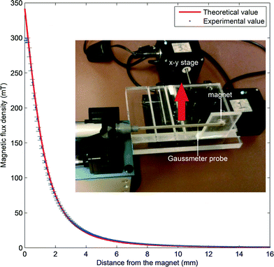 | ||
| Fig. 3 Magnetic flux density versus the distance to the permanent magnet. Points with error bars are measurement data; the line is the plot of eqn (2). Inset: Setup of the measurement. | ||
From the experimental data in Fig. 3 and eqn (3), the relationship between flux density B and the distance d can be simplified to the scaling relationship  . Thus, the distance of the floating marble from the permanent magnet d as well as the concentration of iron oxide c will affect the driving magnetic force of the marble. We hypothesise that if d increases and c decreases, the magnetic force becomes weaker. As a result, the floating marble will start to lag behind the moving permanent magnet until reaching a limit and dislodge.
For a sphere with a radius r moving on a planar air–water interface, the friction force can be calculated by adding a dimensionless correction factor to the Stokes friction:39
| Ff = 6βπrμν = Crμν | (4) |
Assuming that the contact radii of floating magnetic marbles influenced by the vertical component of the magnetic force have similar orders of magnitude as the non-magnetic ones, the marble radius r0 is in the order of 10−4 m for the volumes used. The speed v is in the order of 10−4 to 10−3 m s−1. The viscosity μ is in the order of 10−3 Pa s. The friction factor C is in the order of 10. Therefore, the friction force is estimated to be in the orders of 10−9 to 10−10 N. The scaling relationship between friction force and speed is simplified as:
| Ff ∝ ν | (5) |
The impact of the vertical forces can be shown via usage of different magnetite concentrations. As the concentration increases, the vertical magnetic force experienced by the marble increases. With an increasing downward force, the effective bond number Boeff is expected to increase as well, since:
 | (6) |
 | (7) |
 | (8) |
Sliding of the floating liquid marble
Because the steady motion of the floating marble results from the balance between the horizontal component of the magnetic force and the friction force, both magnetic force and friction force were varied in our experiment to determine the operation map. We investigate the movement of the floating marble in terms of displacement and velocity with the variation of each parameter. According to eqn (2), the magnetic force can be tuned by adjusting the flux density B and the flux density gradient dB/dx through the distance d between the magnet and the marble. The magnetic force will decrease with an increasing distance. Another way to vary the magnetic force is to change the volume V of the iron oxide particles. A higher concentration will result in a larger volume of iron oxide for actuation. According to eqn (5), the friction force is adjusted with the speed v of the permanent magnet. The higher the speed, the larger is the friction force.Three parameters were varied in our experiment: five different distances of the floating marble from the magnet d ranging from 6 mm to 16 mm, three concentrations of iron oxide c ranging from 1 mg ml−1 to 5 mg ml−1 and nine magnet velocities v ranging from 0.465 mm s−1 to 4.19 mm s−1.
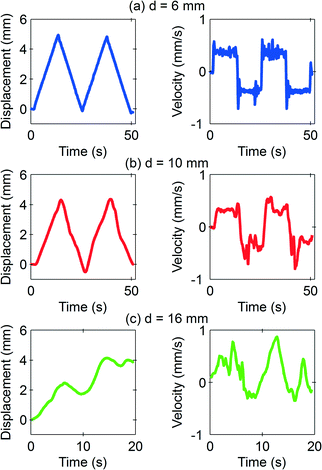
If the permanent magnet is slow and close to the marble, the resulting strong magnetic force causes the floating marble to slide and to follow the magnet with the same velocity. For the potential use of this system as a digital microfluidics system, this is the preferred operating condition. Fig. 4(a) shows a smooth marble movement from stationary to a distance of 4.96 mm before turning back to the other direction, as programmed for the magnet. Fig. 4(b) and (c) show the behaviour of the marble with increasing distance from the magnet, while the iron oxide concentration and the velocity were fixed at 3 mg ml−1 and 0.465 mm s−1, respectively. At d = 10 mm, the marble starts to lag behind the magnet. At a further distance of d = 16 mm, the marble dislodged from the movement of the permanent magnet. Although the initial driving force is big enough to induce a momentum to the marble, the friction force is dominant and the marble cannot keep up with the magnet.
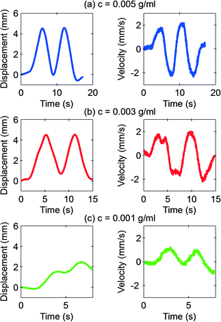
Fig. 5 shows the representative behaviour of the marble with varying concentrations of the iron oxide. The distance from the magnet was chosen as d = 10 mm, and the velocity was fixed at v = 1.86 mm s−1. The marble slides along with the magnet at concentrations of 3 mg ml−1 and 5 mg ml−1. However, at the concentration of 1 mg ml−1, the floating marble no longer follows the moving magnet.
Fig. 6 shows the representative behaviour of the marble at the highest velocity 4.19 mm s−1. At this high velocity, the friction force becomes dominant and the marble tends to lag behind. The marble slides with the magnet with velocity ranging from 0.465 mm s−1 to 1.86 mm s−1. Beyond that, the marble lags behind until it starts to dislodge at 4.46 mm s−1.
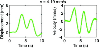 | ||
| Fig. 6 Measured displacement and velocity of a 5 μL floating marble at a distance of 10 mm from the permanent magnet and with an iron oxide concentration of 3 mg ml−1 at the velocity of 4.19 mm s−1. | ||
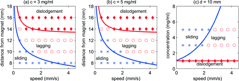
As a summary, Fig. 7 shows the operating maps of the floating marble in the corresponding d–v and c–v spaces. Three zones were identified: sliding, lagging and dislodgment. When Fm ≈ Ff, the marble slides following the magnet to the pre-programed distance of 4.96 mm with the same velocity as that of the magnet. When Fm < Ff, the marble lags behind and if the maximum velocity is reached, it will dislodge from the influence of the magnet. Fig. 7(a) and (b) show the operating map of two different concentrations of iron oxide. A higher concentration shows better control of the movement when the distance of the marble from the magnet and speed increased. As discussed previously, a higher concentration causes a higher friction force due to the larger vertical magnetic force and the resulting larger contact radius (eqn (8)). However, a higher concentration also leads to a higher driving horizontal magnetic force. As a result, the change in concentration does not significantly affect the operation map in d–v space. Fig. 7(c) shows the operation map in the c–v space, a concentration of 1 mg ml−1 and below is not strong enough to let the marble follow the magnet.
Scaling analysis and operating regions
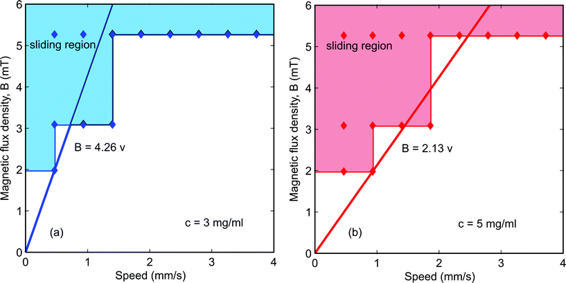
At the lowest magnetic flux density Bmin, the floating marble follows the magnet until the maximum velocity is reached. To simplify the equation for scaling analysis, the force balance in the sliding operating region is| Fm = Ff | (9) |
| αBmin = βνmax | (10) |
 | (11) |
A linear scaling relationship of eqn (7) is fitted to the experimental data of Fig. 8. To get the slope β/α, we chose the critical condition for the sliding regime for both of the concentrations. The minimum magnetic flux density of 1.98 mT and the maximum velocity of 0.465 mm s−1 were chosen for the concentration of 0.003 g ml−1. The minimum magnetic flux density of 1.98 mT and the maximum velocity of 0.930 mm s−1 were chosen for the 0.005 g ml−1 concentration. The slopes are 4.26 Ts m−1 and 2.13 Ts m−1, respectively. Referring back to eqn (2) and taking into account that the concentration of iron oxide is directly proportional to its volume, α represents the term  . Whilst
  remain the same for both cases, we find the product of the proportional factor and the concentration. The data in Fig. 8(a) leads to B = (4.26 × 0.003)v = 0.013v, while the data in Fig. 8(b) leads to B = (2.13 × 0.005)v = 0.011v. The slight difference may be attributed to the term dB/dx. Thus, discounting the concentration of iron oxide, the data of Fig. 8(a) and (b) agree relatively well.
4. Conclusion
This paper investigates experimentally the sliding motion of a magnetically actuated floating liquid marble. Using a permanent magnet, the movement of a floating liquid marble consisting of iron oxide is able to be controlled. While the shape and size of the permanent magnet were fixed, the concentration of iron oxide in the marble and the distance of the marble from the permanent magnet were varied. The key to a controlled movement is to supply adequate actuation force to oppose its frictional force, which is contributed by the velocity of the pulling permanent magnet. In general, the suitable sliding condition is a low speed of the permanent magnet, a high magnetic flux density and a high concentration of magnetic particles in the floating liquid marble. The critical magnetic parameters and velocities derived from the scaling analysis fit well to the experimental data describing the sliding region. Magnetic particles are required for the actuation of the floating liquid marble. Previous works indicated that magnetic particles as used in our experiments are biocompatible.41 For instance, human endothelial cells exposed to such particles are viable for up to 24 hours as reported in a recent study.42 Biocompatibility can be further improved by coating magnetic particles with surfactants such as sodium oleate or polyethylene glycol (PEG).43 Thus, we propose that the digital microfluidics platform investigated in this paper may be used as a bioreactor for growing cells.Acknowledgements
We acknowledge Queensland Micro- and Nanotechnology Centre for providing the facilities to make the experiments possible. This work was performed in part at the Queensland node of the Australian National Fabrication Facility, a company established under the National Collaborative Research Infrastructure Strategy to provide nano- and microfabrication facilities for Australia's researchers.References
- K. Choi, A. H. Ng, R. Fobel and A. R. Wheeler, Annu. Rev. Anal. Chem., 2012, 5, 413–440 CrossRef CAS PubMed.
- M. Abdelgawad and A. R. Wheeler, Adv. Mater., 2009, 21, 920–925 CrossRef CAS.
- C. H. Ooi, A. van Nguyen, G. M. Evans, O. Gendelman, E. Bormashenko and N.-T. Nguyen, RSC Adv., 2015, 5, 101006–101012 RSC.
- M. Paven, H. Mayama, T. Sekido, H. J. Butt, Y. Nakamura and S. Fujii, Adv. Funct. Mater., 2016 DOI:10.1002/adfm.201600034.
- P. Aussillous and D. Quéré, Nature, 2001, 411, 924–927 CrossRef CAS PubMed.
- E. Bormashenko, Y. Bormashenko, A. Musin and Z. Barkay, ChemPhysChem, 2009, 10, 654–656 CrossRef CAS PubMed.
- E. Bormashenko, R. Pogreb, Y. Bormashenko, A. Musin and T. Stein, Langmuir, 2008, 24, 12119–12122 CrossRef CAS PubMed.
- E. Bormashenko, Y. Bormashenko, R. Grynyov, H. Aharoni, G. Whyman and B. P. Binks, J. Phys. Chem. C, 2015, 119, 9910–9915 CAS.
- E. Bormashenko, Y. Bormashenko and A. Musin, J. Colloid Interface Sci., 2009, 333, 419–421 CrossRef CAS PubMed.
- E. Bormashenko, Y. Bormashenko, A. Musin and Z. Barkay, ChemPhysChem, 2009, 10, 654–656 CrossRef CAS PubMed.
- P. Aussillous and D. Quere, Proc. - R. Soc. Edinburgh, Sect. A: Math., 2006, 462, 973–999 CrossRef CAS.
- G. McHale and M. I. Newton, Soft Matter, 2011, 7, 5473–5481 RSC.
- E. Bormashenko, Soft Matter, 2012, 8, 11018–11021 RSC.
- E. Bormashenko, Curr. Opin. Colloid Interface Sci., 2011, 16, 266–271 CrossRef CAS.
- C. H. Ooi and N.-T. Nguyen, Microfluid. Nanofluid., 2015, 1–13 Search PubMed.
- M. I. Newton, D. L. Herbertson, S. J. Elliott, N. J. Shirtcliffe and G. McHale, J. Phys. D: Appl. Phys., 2007, 40, 20–24 CrossRef CAS.
- Y. Zhao, J. Fang, H. Wang, X. Wang and T. Lin, Adv. Mater., 2010, 22, 707–710 CrossRef CAS PubMed.
- Y. Zhao, Z. G. Xu, M. Parhizkar, J. Fang, X. G. Wang and T. Lin, Microfluid. Nanofluid., 2012, 13, 555–564 CrossRef CAS.
- Y. Xue, H. Wang, Y. Zhao, L. Dai, L. Feng, X. Wang and T. Lin, Adv. Mater., 2010, 22, 4814–4818 CrossRef CAS PubMed.
- E. Bormashenko, R. Balter and D. Aurbach, Appl. Phys. Lett., 2010, 97, 091908 CrossRef.
- S. Fujii, S. Kameyama, S. P. Armes, D. Dupin, M. Suzaki and Y. Nakamura, Soft Matter, 2010, 6, 635–640 RSC.
- S. Fujii, M. Suzaki, S. P. Armes, D. Dupin, S. Hamasaki, K. Aono and Y. Nakamura, Langmuir, 2011, 27, 8067–8074 CrossRef CAS PubMed.
- M. Inoue, S. Fujii, Y. Nakamura, Y. Iwasaki and S.-I. Yusa, Polym. J., 2011, 43, 778–784 CrossRef CAS.
- M. Dandan and H. Y. Erbil, Langmuir, 2009, 25, 8362–8367 CrossRef CAS PubMed.
- A. Tosun and H. Y. Erbil, Appl. Surf. Sci., 2009, 256, 1278–1283 CrossRef CAS.
- J. Tian, N. Fu, X. D. Chen and W. Shen, Colloids Surf., B, 2013, 106, 187–190 CrossRef CAS PubMed.
- R. K. Vadivelu, C. H. Ooi, R.-Q. Yao, J. T. Velasquez, E. Pastrana, J. Diaz-Nido, F. Lim, J. A. Ekberg, N.-T. Nguyen and J. A. St John, Sci. Rep., 2015, 5, 15083 CrossRef CAS PubMed.
- T. Arbatan, A. Al-Abboodi, F. Sarvi, P. P. Chan and W. Shen, Adv. Healthcare Mater., 2012, 1, 467–469 CrossRef CAS PubMed.
- F. Sarvi, K. Jain, T. Arbatan, P. J. Verma, K. Hourigan, M. C. Thompson, W. Shen and P. P. Y. Chan, Adv. Healthcare Mater., 2014, 77–86, DOI:10.1002/adhm.201400138.
- J. Tian, T. Arbatan, X. Li and W. Shen, Chem. Commun., 2010, 46, 4734–4736 RSC.
- J. Tian, T. Arbatan, X. Li and W. Shen, Chem. Eng. J., 2010, 165, 347–353 CrossRef CAS.
- L.-H. Lu, K. S. Ryu and C. Liu, J. Microelectromech. Syst., 2002, 11, 462–469 CrossRef CAS.
- Z. Long, A. M. Shetty, M. J. Solomon and R. G. Larson, Lab Chip, 2009, 9, 1567–1575 RSC.
- W. H. Koh, K. S. Lok and N.-T. Nguyen, J. Fluids Eng., 2013, 135, 021302 CrossRef.
- N.-T. Nguyen, G. Zhu, Y.-C. Chua, V.-N. Phan and S.-H. Tan, Langmuir, 2010, 26, 12553–12559 CrossRef CAS PubMed.
- J. R. Dorvee, A. M. Derfus, S. N. Bhatia and M. J. Sailor, Nat. Mater., 2004, 3, 896–899 CrossRef CAS PubMed.
- L. Zhang, D. Cha and P. Wang, Adv. Mater., 2012, 24, 4756–4760 CrossRef CAS PubMed.
- S. S. Shevkoplyas, A. C. Siegel, R. M. Westervelt, M. G. Prentiss and G. M. Whitesides, Lab Chip, 2007, 7, 1294–1302 RSC.
- J. T. Petkov, N. D. Denkov, K. D. Danov, O. D. Velev, R. Aust and F. Durst, J. Colloid Interface Sci., 1995, 172, 147–154 CrossRef CAS.
- C. H. Ooi, C. Plackowski, A. V. Nguyen, R. K. Vadivelu, J. A. S. John, D. V. Dao and N.-T. Nguyen, Sci. Rep., 2016, 6, 21777 CrossRef CAS PubMed.
- T. K. Indira and P. K. Lakshmi, Int. J. Pharm. Sci. Nanotechnol., 2010, 3, 1035–1042 CAS.
- A. Hanini, A. Schmitt, K. Kacem, F. Chau, S. Ammar and J. Gavard, Int. J. Nanomed., 2011, 6, 787–794 CAS.
- J. Sun, S. B. Zhou, P. Hou, Y. Yang, J. Weng, X. H. Li and M. Y. Li, J. Biomed. Mater. Res., Part A, 2007, 80, 333–341 CrossRef PubMed.
| This journal is © The Royal Society of Chemistry 2016 |

