
 Open Access Article
 This Open Access Article is licensed under a
 Creative Commons Attribution 3.0 Unported Licence
Lab on a stick: multi-analyte cellular assays in a microfluidic dipstick†
Nuno M.
Reis
*a,
Jeremy
Pivetal
b,
Ana L.
Loo-Zazueta
a,
João M. S.
Barros
b and
Alexander D.
Edwards
*b
aDepartment of Chemical Engineering, Loughborough University, Leicestershire, LE11 3TU, UK. E-mail: n.m.reis@lboro.ac.uk; Fax: +44 (0)1509 223 923; Tel: +44 (0)1509 222 505
bReading School of Pharmacy, University of Reading, Whiteknights, Reading RG6 6AD, UK. E-mail: a.d.edwards@reading.ac.uk; Fax: +44 (0)118 378 6562; Tel: +44 (0)118 378 4253
First published on 23rd June 2016
Abstract
A new microfluidic concept for multi-analyte testing in a dipstick format is presented, termed “Lab-on-a-Stick”, that combines the simplicity of dipstick tests with the high performance of microfluidic devices. Lab-on-a-stick tests are ideally suited to analysis of particulate samples such as mammalian or bacterial cells, and capable of performing multiple different parallel microfluidic assays when dipped into a single sample with results recorded optically. The utility of this new diagnostics format was demonstrated by performing three types of multiplex cellular assays that are challenging to perform in conventional dipsticks: 1) instantaneous ABO blood typing; 2) microbial identification; and 3) antibiotic minimum inhibitory (MIC) concentration measurement. A pressure balance model closely predicted the superficial flow velocities in individual capillaries, that were overestimated by up to one order of magnitude by the Lucas–Washburn equation conventionally used for wicking in cylindrical pores. Lab-on-a-stick provides a cost-effective, simple, portable and flexible multiplex platform for a range of assays, and will deliver a new generation of advanced yet affordable point-of-care tests for global diagnostics.
Introduction
The benefits of bioassay miniaturization are well described1 and in recent years increased interest in decentralised diagnostics has catalyzed the rapid development of several generations of microfluidic lab-on-a-chip systems including lab-in-a-foil,2 lab-on-paper,3 patterned paper,4–6 lab-on-a-disk,7 lab-on-a-DVD,8 lab-on-a-syringe9 and ‘Shrinky-dink’ microfluidics.10 Dipsticks are a far older testing format familiar in environments as diverse as the garden (soil pH strips), bathroom (urinalysis strips and home pregnancy lateral flow tests), or pharmacy (blood glucose or urinalysis strips), and can analyze targets ranging from protons (pH paper) through to proteins.11 Although dipstick tests are low cost and simple to use, they are unable to assay particulate samples such as cellular assays that measure or detect live cells.12 Current lab-on-a-chip systems are unable to compete directly with lateral flow tests with respect to simplicity of use and manufacturing costs. There remains a need for a miniaturised platform capable of combining the reduced sample volume and assay times of microfluidic systems together with the simplicity and low cost of dipstick tests for cellular analysis.New approaches for one-step microfluidic bioassays have been recently reported, mainly fabricated from PDMS. Samples are traditionally loaded in microfluidic devices using syringes,13 electrokinetics,14 or centrifugal forces,7 however pressure-driven delivery methods have the disadvantage of requiring external bulky equipment. Inspired by lateral flow tests new miniaturised devices were recently developed operating by capillary action.15–17 The advantages and applications of microfluidic diagnostic devices working with capillary action are extensively discussed elsewhere.18–20In situ delivery of assay reagents in capillary-driven microfluidic devices is not trivial, and new approaches included inkjet printing;15 embedding in a substrate-copolymerized hydrogel network;21 use of a dissolvable reagents membrane;22 or trapping within a soluble PEG-based coating.23
Fluorinated ethylene propylene (commercially known as Telfon® FEP) is a copolymer of hexafluoropropylene and tetrafluoroethylene, belonging to a class of fluorocarbon-based polymers with multiple strong carbon–fluorine bonds characterised by a refractive index close to that of water and hydrophobic surface. Our research group has recently pioneered rapid and high sensitivity sandwich immunoassays in FEP microfluidic devices24–26 characterised by simple connectivity, facile to multiplexing and low manufacturing cost. The optical properties of FEP favours optical interrogation of bioassays with e.g. smartphones,26 however the hydrophobic nature of Teflon® FEP remains incompatible with the capillary action required for simple, one-step microfluidic bioassays.
We present in Fig. 1 a new microfluidic lab-on-a-stick approach which uniquely combines key features of dipstick tests with the fluidic format and capabilities of microfluidic lab-on-a-chip systems, namely: 1) simple use – just dip and read; 2) low cost and scalable manufacture; 3) reagents stored dry and released into the sample; and 4) reagents in different locations allowing multiple tests to be performed on a single sample. Since lab-on-a-stick is a microfluidic system, it is suitable for particulate samples including cellular analysis.27,28 Lab-on-a-stick test strips are produced by surface modification of fluoropolymer microcapillary film (MCF), a low-cost mass manufactured microengineered material capable of performing multiple quantitative and sensitive assays in an array of cylindrical microfluidic channels embedded in an optically transparent ribbon.29 The excellent optical transparency of the fluoropolymer MCF material is ideal for naked eye detection or measurement with portable, inexpensive optoelectronic equipment including a smartphone camera26 that cannot be matched by a bundle of individual microcapillaries as previously explained in Edwards et al.30 In contrast to previous work that demonstrated biomarker measurement by heterogeneous immunoassays in fluoropolymer MCFs, the novelty of the lab-on-a-stick lies in the instant homogeneous assay format and the application to a broad range of different assays for testing cellular samples.
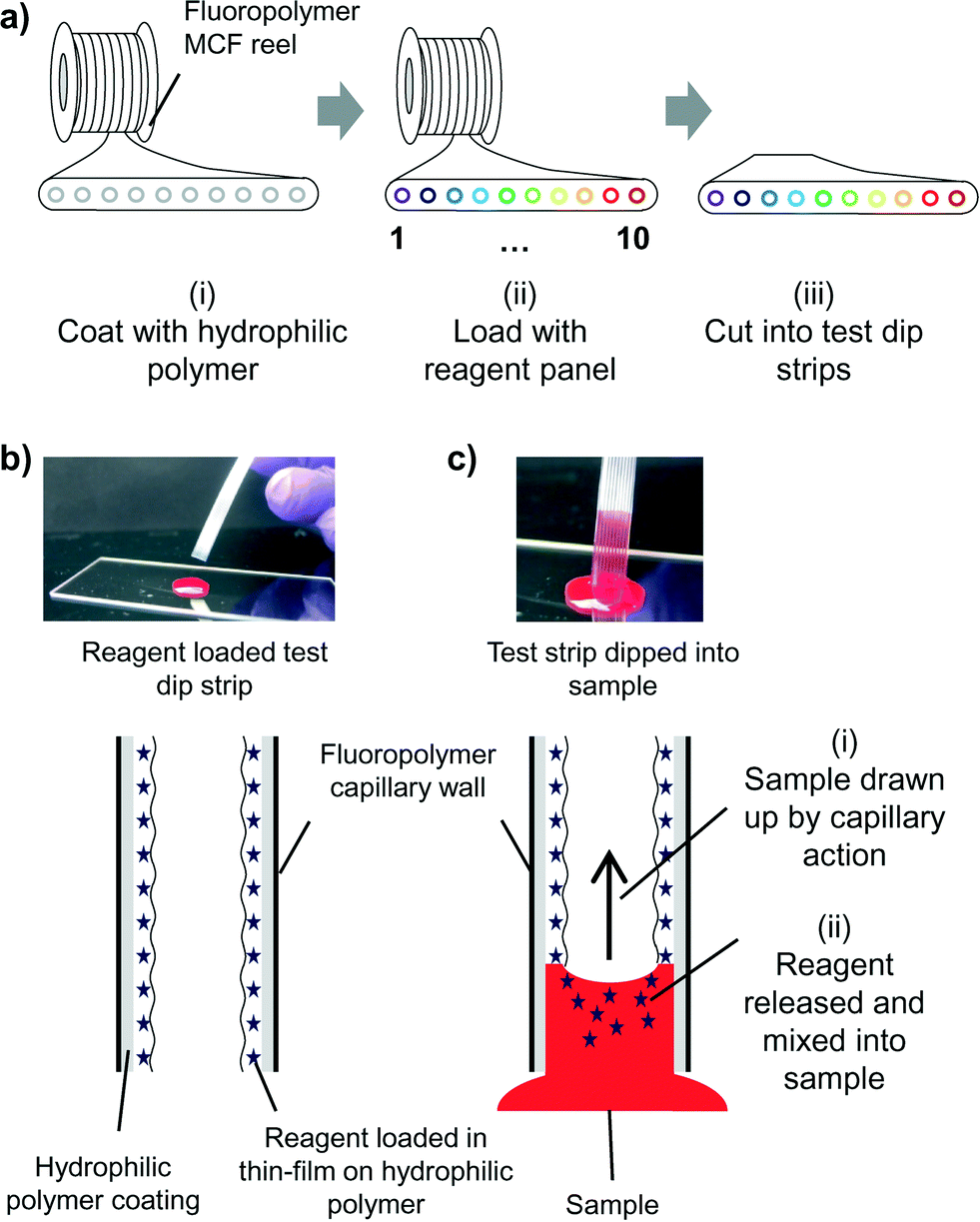 | ||
| Fig. 1 Lab-on-a-stick assay concept. a) Mass manufacturing of multiplex test strips requires three simple steps: i) the internal surface of melt-extruded fluoropolymer MCF containing 10 microcapillaries is bulk coated with a hydrophilic crosslinked PVOH layer. ii) Individual capillaries are loaded in bulk with reagent solutions, and then excess reagents removed leaving a thin film of reagent deposited on the inner surface of the microcapillaries which is then dried. iii) Single dip-strip test devices are prepared by trimming the long MCF reel. b) Each microcapillary within the dip-strip contains a hydrophilic coating covered with a thin film of dried reagent(s). c) When dipped into an aqueous fluid such as blood, i) the sample is drawn up by capillary action into all 10 microcapillaries and ii) reagents quickly released, performing multiple microfluidic assays. | ||
Experimental
Hydrophilic coating of microcapillary film
MCF was produced by Lamina Dielectrics Ltd (Billingshurst, West Sussex, UK) from Teflon® FEP (Dupont, USA) using a melt-extrusion process,29 and consisted of an array of 10 parallel microcapillaries with a mean hydraulic diameter of 206 ± 12.6 μm. The fluoropolymer MCF was subsequently modified by coating the inner surface of the microcapillaries with a permanent hydrophilic layer of PVOH. This involved recirculating at a flow rate of 50 mL h−1 overnight a volume of 100 mL of a 5 mg mL−1 solution of poly(vinyl alcohol) (PVOH) in water (MW 13![[thin space (1/6-em)]](https://www.rsc.org/images/entities/char_2009.gif) 000–23000, >98% hydrolysed for ABO blood grouping experiments; MW 146000–186000, >99% hydrolysed for bacteria and MIC testing – all from Sigma-Aldrich, UK). A 6 m long fluoropolymer MCF was attached to a FPLC P-500 Pharmacia Biotech pump using Upchurch flangeless tube fittings (Kinesis, UK). The PVOH coating was then crosslinked with glutaraldehyde by manually filling the MCF with a freshly prepared 5 mg mL−1 of PVOH solution containing 5 mM of glutaraldehyde (Sigma-Aldrich, UK) and 5 mM HCl (Sigma-Aldrich, UK) for 2 hours at 37 °C, followed by manual washing with water and drying with multiple changes of air using a 50 mL syringe.
000–23000, >98% hydrolysed for ABO blood grouping experiments; MW 146000–186000, >99% hydrolysed for bacteria and MIC testing – all from Sigma-Aldrich, UK). A 6 m long fluoropolymer MCF was attached to a FPLC P-500 Pharmacia Biotech pump using Upchurch flangeless tube fittings (Kinesis, UK). The PVOH coating was then crosslinked with glutaraldehyde by manually filling the MCF with a freshly prepared 5 mg mL−1 of PVOH solution containing 5 mM of glutaraldehyde (Sigma-Aldrich, UK) and 5 mM HCl (Sigma-Aldrich, UK) for 2 hours at 37 °C, followed by manual washing with water and drying with multiple changes of air using a 50 mL syringe.
Measurement of contact angle
The equilibrium contact angle for both uncoated and PVOH coated FEP microcapillary film was determined using the capillary rise method. A 15 cm long dried MCF strip was immersed in deionised water in a transparent reservoir, and the difference between liquid level within each capillary and liquid level in the reservoir, H recorded. For uncoated MCF (hydrophobic, yielding negative liquid rise) the strip was immersed until a meniscus was visible within all 10 capillaries. For hydrophilic (positive liquid rise) the strip was immersed 10 mm into the water and meniscus allowed to equilibrate before recording the position. Due to the nature of melt-extrusion process, capillaries at the edge are slightly flattened and smaller because of the drawing ratio, consequently the equilibrium contact angle in the elliptical microcapillaries was estimated from liquid height based on a modified Young–Laplace's equation: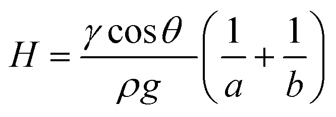 | (1) |
Reagent loading
The method used for loading reagents is simple, scalable and rapid (Fig. 1a and 2). Concentrated solutions of assay reagent or reagent mixtures were filled into individual capillaries (Fig. 2a) in bulk reels of 0.5–5.0 meters of PVOH coated MCF. After a short incubation (from 5 minutes up to 2 hours), the bulk loading solution was removed leaving behind a thin yet uniform liquid film containing reagents (Fig. 2b), and if required, the deposited liquid reagent film was gently dried with dry air or nitrogen.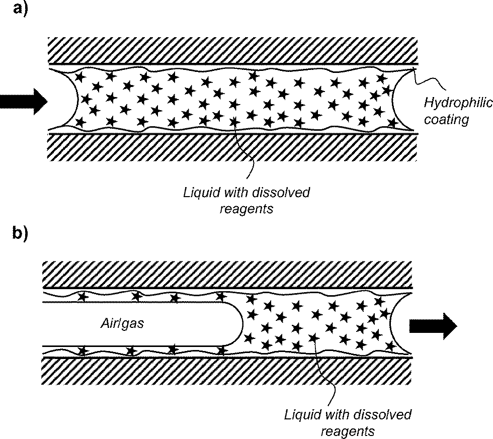 | ||
| Fig. 2 Reagents loading in the PVOH-coated microcapillaries. a) Capillaries are fully loaded with reagents solution. b) Excess liquid is removed by aspirating air or inert gas, leaving behind a thin film of reagents deposited on the wall of the capillaries. | ||
Efficiency of reagent loading
For quantitation of reagents deposition in the PVOH coated MCF, individual microcapillaries within a reel of 200–2000 mm were filled using a 30G needle with the appropriate reagent solutions, and after 5 min the excess loading solution was removed by manually injecting air into all capillaries with a 50 mL plastic syringe. The released reagent concentrations were measured by dipping one or more 80 mm long loaded MCF strip into water and allowing microcapillaries to fill completely by capillary action, incubating for 5 min, and then completely removing released solution, followed by quantitation of released reagent concentration in eluted sample by UV absorbance (antibody), enzymatic end-point assay (glucose), or by quantitative LC-MS (antibiotics).Proof-of-concept lab-on-a-stick assays
For ABO blood typing, microcapillaries were loaded with ALBAclone® Monoclonal ABO antisera anti-A, anti-B or anti-D reagents used as supplied, and devices tested with simulated whole blood ALBAcheck®-BGS (Alphalabs, UK), and strips recorded with a CCD camera. For bacterial identification by fermentation, one colony of E. coli (ATCC 25922), S. typhimurium (strain SL3261) or P. aeruginosa (ATCC 27853) on LB agar plates was re-suspended in 100 μl of fermentation broth (0.1 g L−1 Trypticase, 5 g L−1 NaCl) containing 1 mg mL−1 of phenol red (all sourced from Sigma-Aldrich, UK). Test strips loaded with the indicated panel of sugars were then dipped into each bacterial suspension and incubated for 4 h at 37 °C. For antibiotic resistance measurement, 30 cm long PVOH coated MCF strips were loaded with a 2-fold serial dilution of the indicated antibiotic at concentrations ranging from 100 to 0 μg ml−1. The MCF was then trimmed into 40 mm long test strips and dipped into samples containing one bacterial colony re-suspended in 100 μl of Muller Hinton media and diluted 10000 fold in the same media supplemented with 1 mg mL−1 of resazurin and incubated overnight at 37 °C. Colorimetric microbiology test strips were imaged with a Fujifilm XF1 or Canon S120 camera using white background illumination.
Results and discussion
A core step in the development of this novel lab-on-a-stick concept devices is the modification of the internal surface of a 10-bore ∼200 μm internal diameter MCF manufactured from Telfon-FEP® (Fig. 3a) – previously used in our research group to perform rapid, high sensitivity ELISA25,30 – with a hydrophilic coating consisting of cross-linked PVOH which introduced two new features with a single modification step. Firstly, the PVOH coating dramatically reduced the contact angle of the FEP microcapillaries allowing sample uptake by capillary action. Secondly, the PVOH coating also facilitated simple deposition of a very thin film of reagents within the capillaries for in situ reagent delivery. These two key steps were studied in detail.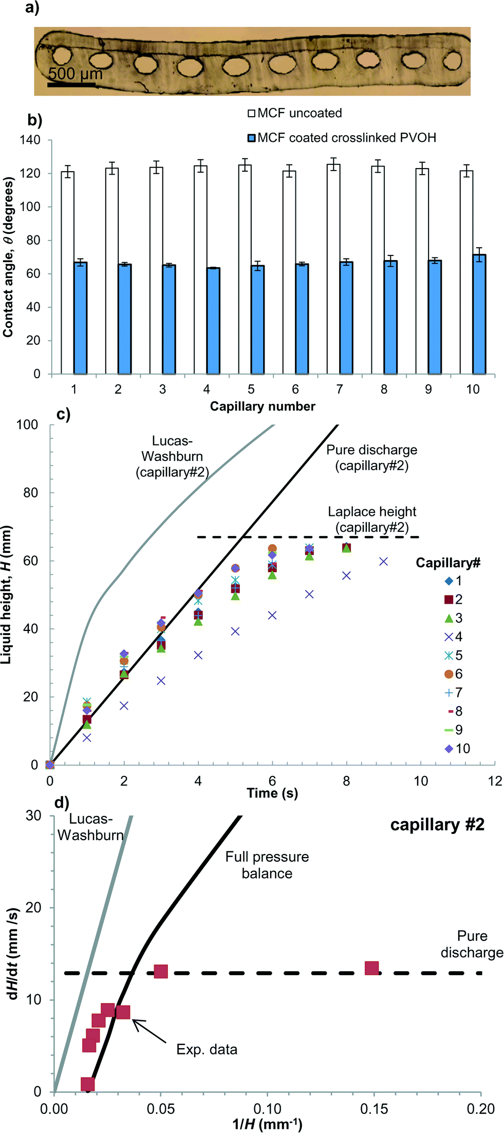 | ||
| Fig. 3 Capillary flow in vertical FEP microcapillaries. a) Microphotograph showing the cross section of the 10-bore FEP microcapillary film. b) Equilibrium contact angle in individual microcapillaries for the MCF uncoated and MCF coated with crosslinked PVOH; error bars represent one standard deviation from at least three experimental replicas. c) Water rise in individual microcapillaries, showing the initial liquid rise follows a pure discharge system that cannot be modelled by Lucas–Washburn equation. d) Modelling of superficial flow velocity, dH/dt in random capillary number 2. | ||
Although commercially known as a non-stick surfaces, fluoropolymers like FEP have been previously coated with cross-linked low-molecular weight PVOH31 or high-molecular weight PVOH,32 the last is extensively described also in US Patent 7179506 B2. Consequently, this work has fully focused on surface modification of FEP microcapillaries with PVOH, to our knowledge something unreported to date.
Liquid rise in FEP-Teflon microcapillaries
The equilibrium contact angle measured with liquid rise experiments and Young–Laplace equation for uncoated fluoropolymer MCF was very high, with a mean value of 123 ± 1.6 degrees across the whole MCF strip (Fig. 3b). The dimensions of individual microcapillaries are shown in Table 1. The cross-section of capillaries was fitted to an ellipse, where a represents the major axis (capillary width) and b the minor axis (capillary depth). The high contact angle of uncoated microcapillaries is linked to the very hydrophobic nature of FEP-Teflon material. The coating procedure reduced the contact angle to 67 ± 2.2 degrees (Fig. 3b), making it possible to drawn up aqueous samples such as whole blood by capillary action without the need of hydraulics. Liquid rise in the parallel array of PVOH coated microcapillaries was found to be fast yet very consistent across the whole 10-bore strip. This is further demonstrated by the film provided in ESI† showing drawn up of whole blood. When capillaries were dried by manually blowing air through the strips using a 50 mL plastic syringe, and liquid height measurements repeated two further times, we noted that the gluteraldehyde crosslinking was important to obtain a stable coating with a contact angle that did not change during reagent loading and sample testing. A detailed characterisation of the inner surface of multiple PVOH-coated microcapilaries by SEM and AFM revealed the PVOH-coating was homogeneous along and across the microcapillaries (see Supplementary methods and Fig. S4 and S5 in ESI†), an important feature for obtaining consistent liquid rise results. The time required for the liquid to reach the maximum (equilibrium) liquid height set by the Laplace pressure was in the order of 10 seconds (Fig. 3c).| Capillary # | Major axis capillary, a (μm) | Minor axis capillary, b (μm) | Hydraulic diameter, dh (μm) | Maximum, equilibrium height, H (mm) |
|---|---|---|---|---|
| 1 | 190.7 | 207.1 | 198.4 | 58.9 ± 3.73 |
| 2 | 182.7 | 249.5 | 208.5 | 58.0 ± 1.73 |
| 3 | 200.4 | 245.1 | 219.4 | 56.7 ± 1.63 |
| 4 | 202.6 | 271.9 | 229.7 | 57.2 ± 0.59 |
| 5 | 200.0 | 282.4 | 230.8 | 54.1 ± 3.90 |
| 6 | 201.6 | 283.3 | 232.3 | 51.7 ± 1.51 |
| 7 | 205.6 | 272.1 | 232.0 | 49.5 ± 2.77 |
| 8 | 196.1 | 238.9 | 214.4 | 52.3 ± 5.16 |
| 9 | 182.7 | 250.9 | 208.9 | 52.8 ± 2.80 |
| 10 | 192.0 | 200.4 | 196.1 | 48.3 ± 7.44 |
Liquid rise in the hydrophilic microcapillaries was successfully modelled by performing a full pressure balance to the microcapillaries:
| ΔPL = ΔPH + ΔPF | (2) |
 | (3) |
| ΔPH = gρH | (4) |
The pressure drop imposed by frictional losses in the capillary is given by the Darcy–Weisbach equation:
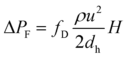 | (5) |
For laminar flow regime, the Darcy friction factor fD is given by:
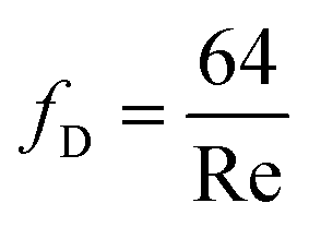 | (6) |
 | (7) |
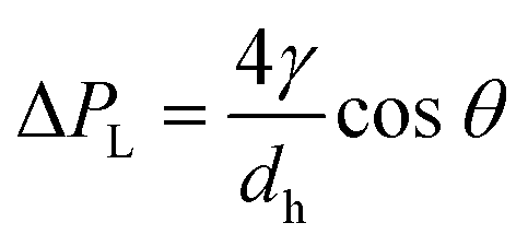
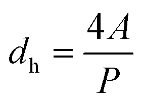
The Laplace pressure in elliptical capillaries is more accurately represented by Young–Laplace's law shown in eqn (1), however for simplicity of the model capillaries were approximated in eqn (3) by considering the hydraulic diameter, dh:
 | (8) |
For horizontal flow in hydrophilic microcapillaries the pressure head term ΔPH in eqn (2) can be neglected, and the pressure balance solved in respect to the superficial flow liquid velocity, u(t) or dH/dt:
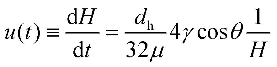 | (9) |
Integration of eqn (9) leads to the well-known Lucas–Washburn equation that governs capillary action in cylindrical pores, including paper33 and nitrocellulose test strips:
 | (10) |
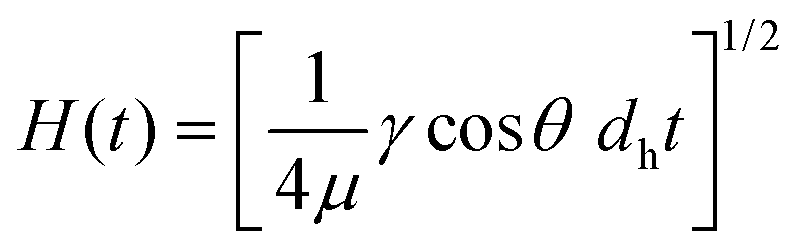
For capillary flow in vertical hydrophilic microcapillaries the full pressure balance in eqn (2) yields the following analytical solution for dH/dt:
 | (11) |
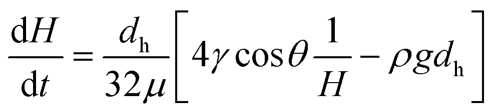
Surprisingly, it was observed that liquid height, H increased linearly with time (Fig. 3c), suggesting capillary flow in the microcapillaries at the initial stages of capillary rise (i.e. up to 40% of Laplace height) is not governed by surface tension, and rather dH/dt followed the superficial flow velocity predicted for gravity discharge from a vertical capillary (Fig. 3d). The pressure balance for gravity emptying of a capillary can be written as:
| ΔPH = ΔPF | (12) |
Note the pressure balance in eqn (12) requires the flow resistance force to have opposite direction to that of the head pressure. The pressure balance can be solved yielding:
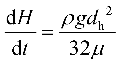 | (13) |
Eqn (13) can be integrated in respect to time yielding:
 | (14) |
The Lucas–Washburn equation was found unable to predict liquid rise in the vertical PVOH coated FEP microcapillaries as shown in Fig. 3c, over-predicting the superficial flow velocity in the capillaries by up to one order of magnitude (Fig. 3d) as it ignores the effect of gravity on the capillary flow. For small values of H (therefore large values of 1/H) the superficial flow velocity in the individual capillaries was consistent with dH/dt values predicted for a pure discharge system represented by eqn (13).
It is unknown the reason why the direction of flow resistance or pressure head forces in eqn (12) is opposite that in eqn (2), but it appears that upon immersing the bottom tip of the PVOH coated microcapillaries in an aqueous liquid, the movement of the air–liquid meniscus is controlled by the speed of wetting, and the hydrophilic nature of the crosslinked PVOH coating creates a “pulling” force similar to that of a mechanical liquid pump. The liquid being “pulled” upwards in the hydrophilic capillary consequently behaves similarly to gravitational emptying of liquid from a vertical hydrophobic capillary. The contact angle appears relevant to set the direction for the force, yet the superficial flow velocity and flow resistance is not dependent on the surface tension force during this stage of “steady” liquid flow. This agrees with pressure balance models that governs e.g. continuous immiscible liquid–liquid flow in microcapillaries, see for example Scheiff et al.34 Once H reached around 40% of the equilibrium Laplace height surface tension governs liquid rise in the capillary, with dH/dt following closely the analytical solution for the full pressure balance in eqn (11) (Fig. 3d).
Note that in order to accurately predict the Laplace height in the elliptical capillaries with eqn (11) – which is based on dh, therefore only accurate for a circular capillary – a best-fitted value for surface tension was used instead, γ = 83.9 mN m−1. This allowed reducing deviations of predicted maximum H from up to 24% down to up to 12%. The Lucas–Washburn equation was unable to predict a maximum liquid rise in a microcapillary, for not considering a maximum equilibrium height in the pressure balance equation.
The full pressure balance model herein presented is essential for understanding the dynamics of fluid wicking in the PVOH-coated microcapillaries, and future studies will look at integration of this model with the control of reagents release from the thin film in the microcapillaries.
Reagent loading
The reagents loading process proved effective for a wide range of assay reagents tested with a broad spectrum of physicochemical properties, ranging from small molecules such as sugars and organic dyes, through to large macromolecules such as antibodies (Table 2). We found that a very wide range of reagents could be loaded as a thin film in the MCF strips coated with crosslinked PVOH (as shown in Fig. 2b), followed by washing the strips with a small volume of water and performing appropriate analysis to the eluted samples to determine by mass balance the overall amount of reagents loaded and released. This is further detailed in Experimental section in the manuscript. The mass fraction of reagents deposited and released varied from 0.8 wt% with trimethoprim to 4.3 wt% with glucose (Table 2). Viscosity and surface tension of each reagent solution was not measured, however there was a clear correlation between the increase in loading efficiency for more concentrated reagent solutions which is linked to a capillary number effect as detailed elsewhere.35,36 The variable loading efficiency seen with some reagents in these proof-of-concept experiments (e.g. ciprofloxacin, Table 1) was subsequently found to be caused by manual reagent loading without carefully controlling the velocity of excess reagent removal, and can be reduced using constant airflow (e.g. using a syringe pump). Note that although loading/release efficiencies appear very low, residual reagent solution removed from the microcapillaries during the wall deposition procedure can be reused, reducing waste. We have subsequently developed a modified procedure that allows 100% efficiency for deposition of assay reagents in the PVOH coated microcapillaries, this will be subject of future publications.| Reagenta | Assay/application | Loading solution concentration | Released concentrationa | Loading efficiency wt% |
|---|---|---|---|---|
| a Released concentrations represent mean ± 1 S.D. of 3 replicate measurements. b ABO agglutinating reagents contained monoclonal agglutinating antibodies plus BSA carrier and therefore total protein concentration was measured. | ||||
| Human IgG | Immunoassay | 15.12 ± 0.02 mg mL−1 | 0.41 ± 0.08 mg mL−1 | 2.7 |
| Mouse IgG | Immunoassay | 900 ± 40 μg mL−1 | 36 ± 9 μg mL−1 | 3.9 |
| Anti-A agglutinating reagentb | ABO blood typing | 4.6 ± 0.4 mg mL−1 | 0.098 ± 0.002 mg mL−1 | 2.1 |
| Anti-B agglutinating reagent | ABO blood typing | 6.2 ± 0.09 mg mL−1 | 0.18 ± 0.02 mg mL−1 | 2.9 |
| Anti-rhesus agglutinating reagent | ABO blood typing | 11 ± 0.1 mg mL−1 | 0.28 ± 0.01 mg mL−1 | 2.5 |
| Glucose | Fermentation | 500 mg mL−1 | 21 ± 2 mg mL−1 | 4.3 |
| Trimethoprim | Antibiotic resistance | 2.5 mg mL−1 | 23 ± 11 μg mL−1 | 0.8 |
| Ciprofloxacin | Antibiotic resistance | 3.0 mg mL−1 | 51 ± 31 μg mL−1 | 1.7 |
The crosslinked PVOH coating was found to be unaffected by reagent loading or release steps. This hydrophilic coating was found to be very stable as ≥80 mm capillary rise was observed in all 10 capillaries of >100 replicate test strips dipped into aqueous samples in many different locations after both extended storage at room temperature, and after international air transportation.
Other methods for entrapment and controlled release of reagents within glass channels and plastic capillaries have been developed in the past exploiting hydrogel layers attached to the internal surface of capillaries37 and microchannels,38 however these may be limited by the slow diffusivity of reagents through the porous hydrophilic layer, and may require reagent loading before assembly of microchannels. Our loading method is simpler, allows more rapid reagent release and efficient mixing with sample at the meniscus, and the use of MCF allows multiple parallel tests to be performed on a single sample. Confocal microscopy of fluorescent antibody confirmed a rapid radial mixing of reagent deposited on the thin film upon the rising of the meniscus, followed by a slower rate of reagent release from the thin film that appeared specific to the molecule (see Fig. S1 and S3†). A possible drawback from this method highlighted from real time confocal fluorescence imaging was the development of a gradient of reagent concentration along the microcapillaries, with maximum concentration in the region around the meniscus. This is further detailed in ESI.†
ABO blood typing
We demonstrated the suitability of the lab-on-a-stick approach for performing assays on eukaryotic cells by developing improved ABO agglutination assays that allow multiplex testing with simplified detection of agglutination. We illustrated this concept by performing instantaneous ABO blood typing but the same principle is valid for related tests such as red blood cell or latex agglutination assays. Individual microcapillaries within a 2 m long hydrophilic coated MCF (Fig. 4a) were loaded with agglutinating antibodies against red blood cell antigens, in particular anti-A, anti-B and anti-D (rhesus factor), and the remaining 4 capillaries left unloaded (working as negative controls), and trimmed into 10 cm long dipsticks. Within few seconds of being dipped into reconstituted blood (with 40% red blood cell content), blood samples rose by capillary action up to ∼80 mm in height. In microcapillaries loaded with agglutinating antibody against red blood cell antigens, aggregation and clustering was rapidly observed indicating positive red blood cell agglutination (Fig. 4). In contrast, in control microcapillaries or those loaded with antibodies against RBC antigens not present on that sample, a uniform red colour was seen indicating lack of agglutination. This is further demonstrated in the film provided in ESI.† Note that in enlarged images shown, capillary 6 for the B+ sample appears less obviously agglutinated than other agglutinated capillaries; in this particular capillary agglutination was more clearly apparent higher up the test strip.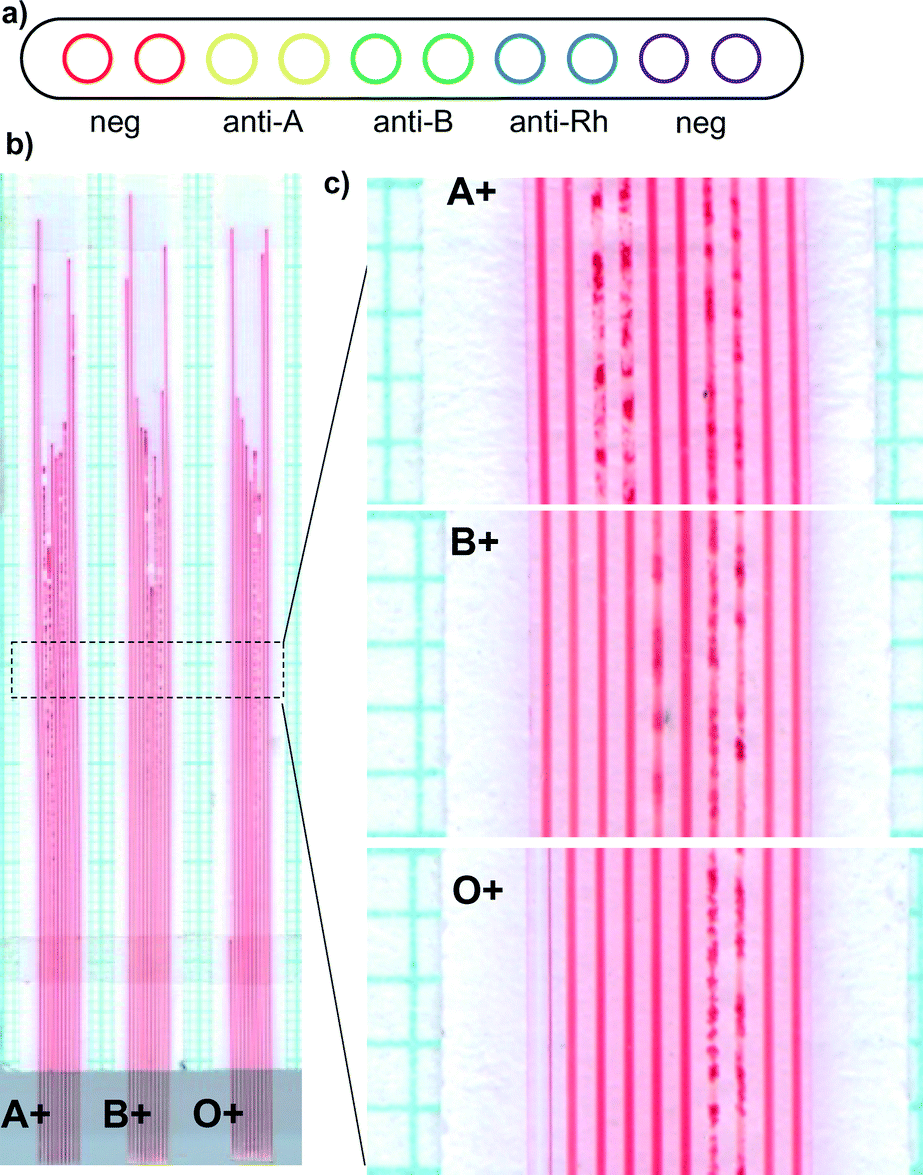 | ||
| Fig. 4 Instantaneous ABO blood typing. a) Hydrophilic coated MCF test strips were loaded with A, B or rhesus blood antigen agglutinating antibodies. b) Test strips were dipped into blood samples and photographed after capillary rise was complete. c) Magnified images of ABO test strips showing capillaries with negative and positive agglutination; agglutination was observed only in capillaries where appropriate blood group antigens were present on RBCs. Image presented representative of >10 independent ABO agglutination assays in lab-on-a-stick test strips. | ||
The agglutination was most intense at the highest point of the blood filled microcapillary, and near the inlet no agglutination was detected, reflecting a more intense agglutination reaction near the meniscus of the fluid. This is linked to the rate of reagents release from the thin film and a level of convective release of reagents generated by the rising meniscus, as detailed in Fig. S1 and S3 in ESI.† In addition, we noticed a reduced capillary rise in capillaries where agglutination was observed (Fig. 4b), this is clearer in strips loaded with only anti-A antibodies in Fig. S6b.† A positive agglutination reaction results in strong binding of RBCs that leads to changes in viscosity and surface tension of the solution, consequently changes in equilibrium liquid height. We also noticed distinct rates of reaction of the different agglutination antibodies, consequently the variability in the terminal liquid height in the multiplexed tests shown in Fig. 4 is intrinsically linked to the combined effect of the rate of release of reagents, the rate of agglutination reaction and changes in physical properties of the fluid.
Potentially the loading and release of reagents from the thin film in the lab-on-a-stick can be optimised for enhancing positive/negative discrimination of the agglutination reaction. In addition, agglutination in microcapillaries provide very clear and simple optical detection of agglutination that is not possible in conventional Eldon card or on a transparent glass slide, as shown in Fig. S6 in ESI.†
Bacterial identification testing
The lab-on-a-stick is also ideally suited to performing assays on prokaryotic cells. We successfully multiplexed and miniaturised classical analytical microbiology tests for phenotypical identification of bacteria and for quantitative measurement of antibiotic susceptibility. These two critical and routine microbiology tests are still confined to the laboratory, and cost-effective rapid and portable versions of laboratory microbiology tests are urgently needed.39 To perform phenotypical identification tests, a panel of sugars was loaded within individual microcapillaries in an hydrophilic coated fluoropolymer MCF at sufficient concentrations to perform fermentation assays in the microcapillaries (Fig. 5a). When test strips were dipped into bacterial colonies resuspended in fermentation medium containing the classical pH indicator phenol red, only in the presence of bacteria capable of fermenting each particular sugar did the pH indicator change colour indicating media acidification (Fig. 5b). This allowed discrimination between E. coli and Salmonella based on lactose fermentation; E. coli and Salmonella enterica are phenotypically very similar, but only E. coli ferments lactose. In contrast, when unable to ferment the sugar, metabolism of media components raised the pH leading to a change from orange to pink. Likewise, with the non-fermenting control organism P. aeruginosa, pH was raised in the presence of all sugars, giving pink colour. Thus careful selection of an intermediate orange indicator colour for the indicator medium allowed for detection of both fermentation lowering pH, and metabolism of other energy sources raising pH.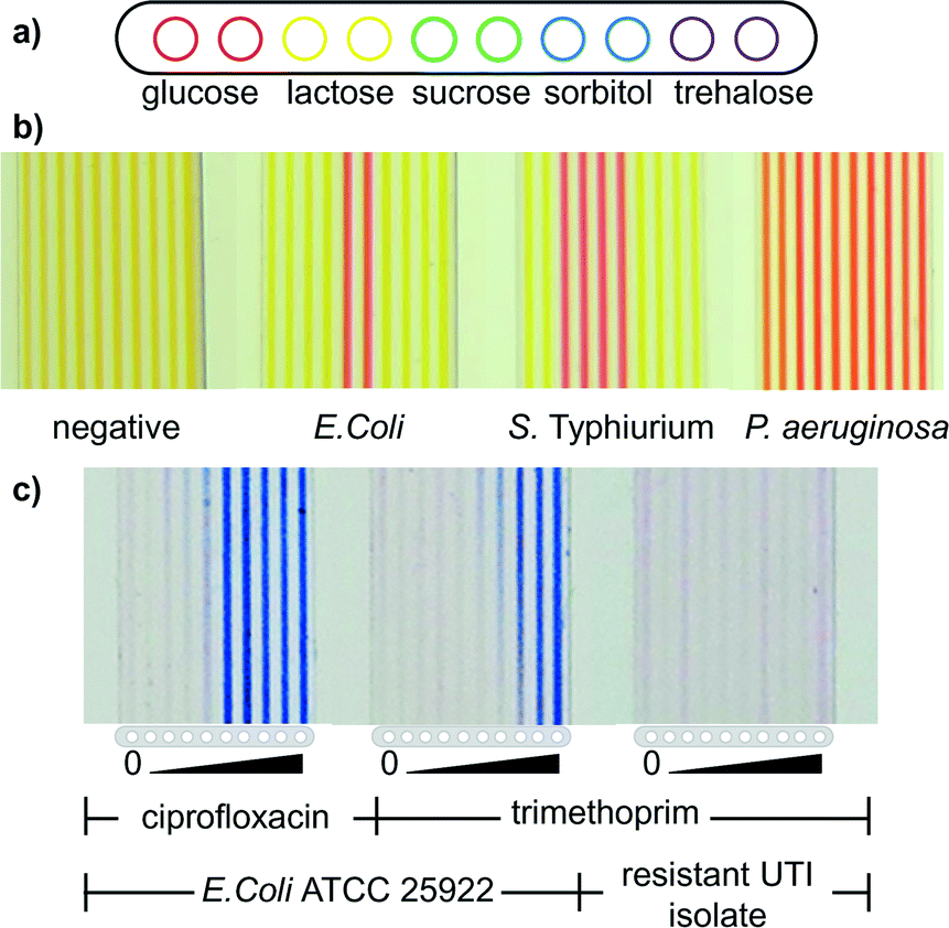 | ||
| Fig. 5 Microfluidic dipstick bacterial identification and antibiotic susceptibility testing. a) Hydrophilic coated FEP MCF was bulk loaded with the 5 indicated sugars, and test strips cut and dipped into individual colonies of the indicated bacteria resuspended in an orange pH indicator broth. b) After 4 h incubation, bacteria capable of fermenting each sugar produced a yellow colour indicating acidification, in contrast to orange-red colour indicating no fermentation. c) MIC test strips loaded with serial dilutions of the indicated antibiotics were dipped into E. coli samples resuspended in resazurin indicator medium, and imaged after overnight incubation. Bacterial growth converted the blue medium through pink to white, and capillaries remained blue when antibiotic concentration sufficient to inhibit growth. Example images of fermentation assays are representative of multiple assays performed with more than 5 different sugars and multiple bacterial samples, and MIC assays are representative of multiple MIC assays performed with a total of 4 different antibiotics and 3 different bacterial strains. Note that image contrast and brightness was adjusted equally for all test strip images. | ||
Although fermentation assays are not alone able to definitively identify bacterial species, they remain the single most commonly used and internationally accepted microbial identification assays. The more different fermentation substrates tested, the more reliably a bacterial sample can be identified, therefore this exemplar cellular assay demonstrates clearly the advantage of low cost multiplex MCF test strips where 10 tests can be performed per test strip, and multiple strips can be used to test a single sample to increase multiplexing beyond 10 assays. The second most common test is enzymatic assays e.g. using colorimetric substrates such as ONPG for beta-galactosidase enzyme, which are likewise ideally suited to performing in lab-on-a-stick test strips. As an example, we demonstrated that the antibiotic resistance enzyme beta-lactamase could be rapidly detected in MCF using the chromogen nitrocefin (Fig. S4†).
Functional minimum inhibitory concentration assays
Given the rise of antimicrobial resistance, it is critically important that we develop improved antibiotic resistance tests. We developed a dipstick microfluidic minimum inhibitory concentration (MIC) assay to quantify antibiotic susceptibility which detects the lowest concentration of antibiotic that inhibits growth. Individual microcapillaries in were loaded with 2-fold serial dilutions of antibiotics, and 30 mm lab-on-a-stick MIC test strips were dipped into E. coli samples resuspended in resazurin growth indicator medium. Following incubation, when bacteria grew inside microcapillaries the indicator medium changed from blue to pink indicative of conversion of resazurin to resorufin, and eventually to white at high bacterial cell density after overnight incubation. In the MIC test strips, colour changed from blue to white only in microcapillaries where the antibiotic concentration was too low to inhibit cell growth. At higher concentrations of antibiotic the capillaries remained blue, demonstrating growth inhibition and thereby the minimal inhibitory concentration (Fig. 5c).Note that although FEP is relatively oxygen permeable as previously reported,40 we have not determined the accessible oxygen levels within MCF test strips, as in common with many other clinically and industrially important bacteria, E. coli are facultative anaerobes and grow both in the presence and absence of oxygen.
MIC values in microfluidic dipstrips were measured by calculating the released concentration of antibiotic in the last capillary that remained blue by multiplying the loading solution concentration by the antibiotic loading efficiency in Table 2. Similar MIC values were obtained to those measured using a conventional resazurin microplate (Fig. S7 and Table S1†) method with ATCC 25922 E. coli strain showing MIC of 0.24 μg mL−1, and 0.011 μg mL−1 for trimethoprim and ciprofloxacin respectively when measured in lab-on-a-stick dipstrips, compared to 0.25 μg mL−1 and 0.015 μg mL−1 measured in microplates (Fig. 5c). When clinical E. coli urinary tract infection (UTI) isolates were tested, for many samples cell growth was observed in all capillaries indicating antibiotic resistance. Antibiotic resistance observed in lab-on-a-stick MIC tests on clinical UTI isolates matched the resistance profile determined using conventional disc diffusion methods. Note that a gradient of cell growth is visible in capillaries at threshold concentrations of antibiotics. This reflects the gradient of antibiotic released into the sample as it rises into the microcapillary, with the highest concentration at the top showing stronger blue colour in contrast to the lower concentration at the bottom where growth is detectable. This gradient of reagent concentration is further detailed in Fig. S2† and found to be minimised by having shorter test strips, potentially providing additional quantitative information about antibiotic susceptibility.
It is important to understand that small variations in bacterial growth and cell density in the presence of a marginal concentration of antibiotic lead to variable MIC observed. This is true even with internationally recognised standardised microplate MIC assays, and with internationally accepted standard reference strains of E. coli, variations over a 4-fold range are considered acceptable.41 Indeed, the parallel microplate assays performed alongside lab-on-a-stick tests showed 2 to 4-fold variation in observed MIC between two repeat tests (see Fig. S4 in ESI†). What is critical is to measure order of magnitude changes in antibiotic sensitivity, with MIC typically tested over a 100–1000-fold range.
The antibiotic loading solution in these proof-of-concept studies were manually removed using a syringe to drive air through, which led to relatively high variation in antibiotic loading seen in Table 1. However, this variation can be eliminated by loading using syringe pumps, and the inherent variation in MIC measurements over a 2- to 4-fold range means that the manually prepared strips remained highly informative in spite of this variability in antibiotic loading.
Conclusions
The new lab-on-a-stick approach is simple yet flexible, uniquely combining the benefits of conventional dipstick tests with the capabilities of microfluidic systems. The coating of FEP microcapillaries with crosslinked PVOH in one step both reduces the contact angle of the FEP microcapillaries for sample uptake by capillary action, and facilitates in situ assay reagent delivery. Sample uptake by capillary action is predictable with a full pressure balance, which considers surface tension, resistive and pressure head forces. Lab-on-a-stick provides a cost-effective, simple, portable and flexible multiplex platform for a range of assays, and this proof-of-concept study should lead to the development of a new generation of advanced yet affordable point-of-care tests for global applications.Acknowledgements
Authors are grateful to Patrick Hester for providing the MCF material, and to EPSRC (grant EP/L013983/1) and Loughborough University for funding.References
- C. D. Chin, V. Linder and S. K. Sia, Lab Chip, 2012, 12, 2118–2134 RSC.
- M. Focke, D. Kosse, C. Müller, H. Reinecke, R. Zengerle and F. von Stetten, Lab Chip, 2010, 10, 1365–1386 RSC.
- W. Zhao and A. van der Berg, Lab Chip, 2008, 8, 1988–1991 RSC.
- A. W. Martinez, S. T. Phillips, M. J. Butte and G. M. Whitesides, Angew. Chem., Int. Ed., 2007, 46, 1318–1320 CrossRef CAS PubMed.
- A. W. Martinez, S. T. Phillips, G. M. Whitesides and E. Carrilho, Anal. Chem., 2010, 82, 3–10 CrossRef CAS PubMed.
- G. G. Lewis, M. J. Ditucci and S. T. Phillips, Angew. Chem., Int. Ed., 2012, 51, 12707–12710 CrossRef CAS PubMed.
- B. S. Lee, J.-N. Lee, J.-M. Park, J.-G. Lee, S. Kim, Y.-K. Cho and C. Ko, Lab Chip, 2009, 9, 1548–1555 RSC.
- H. Ramachandraiah, M. Amasia, J. Cole, P. Sheard, S. Pickhaver, C. Walker, V. Wirta, P. Lexow, R. Lione and A. Russom, Lab Chip, 2013, 13, 1578–1585 RSC.
- M. Mancuso, L. Jiang, E. Cesarman and D. Erickson, in Proceedings of the 16th International Conference on Miniaturized Systems for Chemistry and Life Sciences, MicroTAS 2012, Chemical and Biological Microsystems Society, Okinawa, 2012, pp. 1360–1362 Search PubMed.
- A. Grimes, D. N. Breslauer, M. Long, J. Pegan, L. P. Lee and M. Khine, Lab Chip, 2008, 8, 170–172 RSC.
- B. Ngom, Y. Guo, X. Wang and D. Bi, Anal. Bioanal. Chem., 2010, 397, 1113–1135 CrossRef CAS PubMed.
- G. A. Posthuma-Trumpie, J. Korf and A. van Amerongen, Anal. Bioanal. Chem., 2009, 393, 569–582 CrossRef CAS PubMed.
- C. D. Chin, T. Laksanasopin, Y. K. Cheung, D. Steinmiller, V. Linder, H. Parsa, J. Wang, H. Moore, R. Rouse, G. Umviligihozo, E. Karita, L. Mwambarangwe, S. L. Braunstein, J. van de Wijgert, R. Sahabo, J. E. Justman, W. El-Sadr and S. K. Sia, Nat. Med., 2011, 17, 1015–1019 CrossRef CAS PubMed.
- T. Kawabata, H. G. Wada, M. Watanabe and S. Satomura, Electrophoresis, 2008, 29, 1399–1406 CrossRef CAS PubMed.
- L. Gervais and E. Delamarche, Lab Chip, 2009, 9, 3330–3337 RSC.
- D. Juncker, H. Schmid, U. Drechsler, H. Wolf, M. Wolf, B. Michel, N. De Rooij and E. Delamarche, Anal. Chem., 2002, 74, 6139–6144 CrossRef CAS PubMed.
- G. M. Walker and D. J. Beebe, Lab Chip, 2002, 2, 131–134 RSC.
- M. L. Sin, J. Gao, J. C. Liao and P. K. Wong, J. Biol. Eng., 2011, 5, 6 CrossRef PubMed.
- D. Desai, G. Wu and M. H. Zaman, Lab Chip, 2011, 11, 194–211 RSC.
- C. Rivet, H. Lee, A. Hirsch, S. Hamilton and H. Lu, Chem. Eng. Sci., 2011, 66, 1490–1507 CrossRef CAS.
- H. Wakayama, T. G. Henares, K. Jigawa, S. Funano, K. Sueyoshi, T. Endo and H. Hisamoto, Lab Chip, 2013, 13, 4304–4307 RSC.
- Y. Fujii, T. G. Henares, K. Kawamura, T. Endo and H. Hisamoto, Lab Chip, 2012, 12, 1522–1526 RSC.
- Y. Uchiyama, F. Okubo, K. Akai, Y. Fujii, T. G. Henares, K. Kawamura and T. Yao, Lab Chip, 2012, 12, 204–208 RSC.
- A. P. Castanheira, A. I. Barbosa, A. D. Edwards and N. M. Reis, Analyst, 2015, 140, 5609–5618 RSC.
- A. I. Barbosa, A. P. Castanheira, A. D. Edwards and N. M. Reis, Lab Chip, 2014, 2918–2928 RSC.
- A. I. Barbosa, P. Gehlot, K. Sidapra, A. D. Edwards and N. M. Reis, Biosens. Bioelectron., 2015, 70, 5–14 CrossRef CAS PubMed.
- G. V. Kaigala, R. D. Lovchik and E. Delamarche, Angew. Chem., Int. Ed., 2012, 51, 11224–11240 CrossRef CAS PubMed.
- G. M. Whitesides, Nature, 2006, 442, 368–373 CrossRef CAS PubMed.
- B. Hallmark, F. Gadala-Maria and M. R. Mackley, J. Nonnewton. Fluid Mech., 2005, 128, 83–98 CrossRef CAS.
- A. D. Edwards, N. M. Reis, N. K. H. Slater and M. R. Mackley, Lab Chip, 2011, 11, 4267–4273 RSC.
- G. E. McCreath, R. O. Owen, D. C. Nash and H. A. Chase, J. Chromatogr. A, 1997, 773, 73–83 CrossRef CAS PubMed.
- M. Kozlov, M. Quarmyne, W. Chen and T. J. McCarthy, Macromolecules, 2003, 36, 6054–6059 CrossRef CAS.
- B. Lutz, T. Liang, E. Fu, S. Ramachandran, P. Kauffman and P. Yager, Lab Chip, 2013, 13, 2840–2847 RSC.
- F. Scheiff, M. Mendorf, D. Agar, N. Reis and M. Mackley, Lab Chip, 2011, 11, 1022–1029 RSC.
- C. Eaboratory and B. G. I. Taylor, J. Fluid Mech., 1961, 10, 161–165 CrossRef.
- B. F. P. Bretherton, J. Fluid Mech., 1960, 10, 166–188 CrossRef.
- M. Kataoka, H. Yokoyama, T. G. Henares, K. Kawamura, T. Yao and H. Hisamoto, Lab Chip, 2010, 10, 3341–3347 RSC.
- M. Beck, S. Brockhuis, N. van der Velde, C. Breukers, J. Greve and L. W. M. M. Terstappen, Lab Chip, 2012, 12, 167–173 RSC.
- S. Cohen-Bacrie, L. Ninove, A. Nougairède, R. Charrel, H. Richet, P. Minodier, S. Badiaga, G. Noël, B. la Scola, X. de Lamballerie, M. Drancourt and D. Raoult, PLoS One, 2011, 6, e22403 CAS.
- K. S. Elvira, R. C. R. Wootton, N. M. Reis, M. R. Mackley and A. J. deMello, ACS Sustainable Chem. Eng., 2013, 1, 209–213 CrossRef CAS.
- J. M. Andrews, J. Antimicrob. Chemother., 2001, 48(Suppl 1), 5–16 CrossRef CAS PubMed.
Footnote |
| † Electronic supplementary information (ESI) available: Film showing blood aspiration by capillary action in the hydrophilic coated MCF; film showing blood agglutination in microcapillaries; ESI document including supplementary methods and supplementary results. See DOI: 10.1039/c6lc00332j |
| This journal is © The Royal Society of Chemistry 2016 |