
 Open Access Article
 This Open Access Article is licensed under a Creative Commons Attribution-Non Commercial 3.0 Unported Licence
Selective plane illumination microscopy on a chip†
Petra
Paiè‡
ab,
Francesca
Bragheri‡
 b,
Andrea
Bassi
*a and
Roberto
Osellame
ab
b,
Andrea
Bassi
*a and
Roberto
Osellame
ab
aDipartimento di Fisica, Politecnico di Milano, Piazza Leonardo da Vinci 32, 20133 Milano, Italy. E-mail: andreabassi@polimi.it; Fax: +39 02 2399 6126; Tel: +39 02 2399 6010
bIstituto di Fotonica e Nanotecnologie, CNR, Piazza Leonardo da Vinci 32, 20133 Milano, Italy
First published on 17th March 2016
Abstract
Selective plane illumination microscopy can image biological samples at a high spatiotemporal resolution. Complex sample preparation and system alignment normally limit the throughput of the method. Using femtosecond laser micromachining, we created an integrated optofluidic device that allows obtaining continuous flow imaging, three-dimensional reconstruction and high-throughput analysis of large multicellular spheroids at a subcellular resolution.
Light sheet fluorescence microscopy (LSFM) methods, such as Selective Plane Illumination Microscopy (SPIM),1 have revolutionized the field of biological imaging. In contrast with wide-field and confocal microscopy, they provide fast, high-resolution optical sectioning over large tissue volumes with low photo-toxicity.2–7 LSFM has been used to image biological systems of various spatial scales, from single cells8 to artificial tissues (e.g. tissue spheroids),9,10 and to entire embryos (e.g. Drosophila melanogaster, Danio rerio).11 These samples, normally embedded in a gel, are imaged individually by mounting them one at a time on a microscope. The mounting procedure is time consuming, taking much longer time compared to the acquisition itself and is not compatible with multi-specimen imaging, limiting experimental throughput and statistics.
Application of LSFM to toxicology, drug screening and gene expression studies on a large scale requires new systems able to perform massive recording and analysis of multiple samples. An intense effort has been recently devoted to this topic:12,13 the preferred methods consist of the combination of fluidic capillaries with LSFM setups, or in the integration of light sheet illumination in lab on chips.14 However, these approaches are limited to small specimen imaging14–16 or require the mechanical translation of the whole device with respect to the imaging system, to record the entire samples in 3D.13,17,18 These limitations have hindered high-throughput, three dimensional imaging of biological samples.
Here we present a millimeter-scaled optofluidic lab-on-a-chip that integrates SPIM illumination and continuous sample delivery in a microfluidic channel. The device, fully fabricated by femtosecond laser micromachining, includes an optofluidic cylindrical lens with an aspherical profile to create an aberration-free light sheet illumination across the channel where the sample is circulated by a microfluidic pump. We use this device to automatically scan biological samples under a conventional microscope, without the need of any motorized stage. We demonstrate high-throughput LSFM, segmentation and quantification in thick, three-dimensional cellular tissues.
SPIM employs a cylindrical lens to form a light sheet in a single section of the specimen. Scanning is then normally achieved by moving the sample with a motorized translation stage. In our optofluidic device, the light sheet is created across a microfluidic channel by an embedded cylindrical lens and the scanning is performed by letting the sample flow at a constant speed through the light sheet. The effective integration of the cylindrical lens with the microfluidic channel is enabled by the unique 3D processing capabilities and the high level of precision and control of femtosecond laser micromachining (FLM).19–21 The technique is a two-step fabrication process that consists of: (1) permanent material modification following nonlinear absorption of focused femtosecond laser pulses; (2) etching of the laser modified zone by a hydrofluoric acid (HF) solution. The laser irradiation in a fused silica substrate enhances the etching rate by up to two orders of magnitude with respect to the pristine material, enabling the manufacturing of channels with an arbitrary shape in the bulk glass substrate and high quality surfaces (with roughness as low as 10 nm).22,23
The device concept is represented in Fig. 1a and a picture of the actual implementation is shown in Fig. 1b. The first channel with a rectangular cross-section and an H shape (see Fig. S1†) is connected by tubing to an external microfluidic pump that delivers the sample to the imaging region (Fig. 1c). The cylindrical lens is produced in the same glass chip by a second microfluidic channel with an engineered cross-section (see Fig. S2†) and filled with a high refractive-index fluid (Cargille refractive index liquid, n = 1.56). This optofluidic lens has three main advantages: it is precisely aligned to the microfluidic channel (positioning accuracy of the stages used in the fabrication process is better than 100 nm); its shape can be easily tailored to achieve highly-engineered profiles for aberration-free operation; its focal length can be subsequently adapted to the sample under study by changing the refractive index of the filling liquid. A third channel is created to accommodate a single mode optical fiber delivering the light that will be shaped by the cylindrical lens into the light sheet. After alignment, the fiber is fixed in the microchannel by using index-matching UV-glue. The fluorescence emitted by the illuminated section of the sample is imaged perpendicularly to the light sheet by a microscope objective onto a CCD or CMOS camera. No external moving parts are required to perform the measurement, the light sheet alignment is set once for all and no manual sample positioning is required. The complete optofluidic chip is a very small device (Fig. 1b) that, being monolithic, can be easily mounted on a conventional wide-field microscope (Fig. 1c) or used as the core of a dedicated SPIM setup.
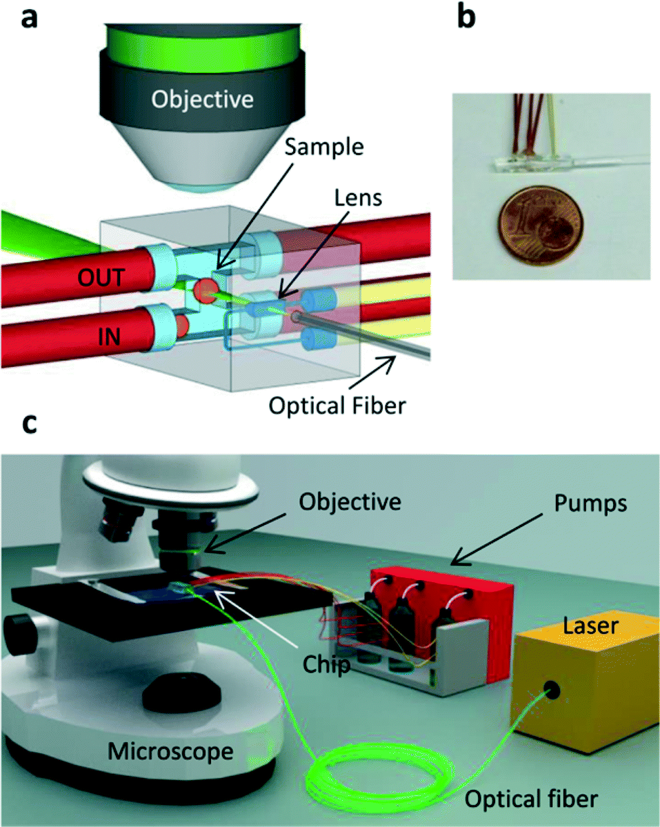 | ||
| Fig. 1 System design. (a) Scheme of the chip: the sample is automatically moved by the flux through an H shaped fluidic network, flowing from the red tube indicated with IN to the red tube indicated with OUT. Two additional tubes (red) are filled with a buffer solution which is used to precisely control the motion of the sample. An optical fiber delivers the light (λ = 532 nm) to the optofluidic lens which creates the light sheet (green) in the center of the H shaped fluidic channel. The yellow tubes are used to fill the lens with a high index of refraction liquid. A microscope objective collects the light emitted perpendicularly from the light sheet. (b) Picture of the chip with 1 € cent coin for size comparison. (c) Scheme of the imaging setup: the chip is placed on a microscope stand, and the sample is collected from a reservoir and delivered to the chip by a pumping system connected to the red tubes. | ||
The versatility of FLM allows the fabrication of devices optimized for samples of different sizes. Here, we demonstrate our integrated-SPIM approach on fixed tissue spheroids (H2B-mCherry expressing spheroids, with ca. 300 μm diameter). These three-dimensional artificial tissues, used in stem cells and oncological research,24 have been extensively imaged with light-sheet microscopy9,10,25 and can potentially be cultured directly on a chip.26 The dimensions of the sample channel, which has a 500 μm side cross section, have to be chosen taking in consideration the sample size. In particular, the channel should be slightly bigger to permit the passage of only one sample per time through the light sheet, avoiding any sample damage that could arise from the contact with the channel walls. Moreover, the channel dimensions and shapes are designed to avoid imaging distortion during the acquisition, which can be derived from the partial interception of the collected fluorescence signal with the lateral walls of the sample channel. The H-shape of the microchannel introduces an auxiliary flow of pure buffer that prevents the spheroid from hitting the opposite wall due to inertia after the 90° turn (see Fig. S1†). This auxiliary flow, controlled by the same four-channel microfluidic pump, is very effective in ensuring that the sample translates vertically, with no spurious rotation and approximately always in the same transversal position while crossing the light sheet (Movie 1). Uniform illumination over the whole sample is achieved by designing a light sheet with a confocal parameter of 400 μm that in turn requires a waist of 5.5 μm (see Fig. S2†).
In order to characterize the light sheet, we created a dedicated chip with an optofluidic lens placed in front of a large reservoir filled with a fluorescent solution. This allowed the visualization of the light sheet propagation and confirmed the targeted confocal parameter and waist (see text and Fig. S3†). We also performed a more accurate characterization, directly in the final device using fluorescent nanobeads. The optical setup consists of a 532 nm laser (Uniphase) coupled into a single mode optical fiber to deliver the light to the chip (ca. 5 mW), and a 20 × NA 0.45 objective (CFI S Plan Fluor ELWD 20X, Nikon) with a long working distance (6.6–8 mm) and correction ring for up to 2 mm glass was used to image the sample, reducing the aberrations caused by the presence of glass and liquid. The objective, in combination with a tube lens (MT-1 Mitutoyo), forms a compact microscope that creates an image on the sensor. We used an electron multiplied CCD camera (Andor, LucaR), running at 12 Hz, to image the samples passing through the light sheet.
The characterization was performed by filling the microchannel with a solution of fluorescent nanobeads, which permitted the acquisition of the point spread function (PSF) in the operative configuration both in the axial and transverse directions (Fig. 2). Moreover, the entire field of view was characterized by circulating the nanobeads at high speed. The acquired intensity image was used to map the light sheet and to correct possible in-homogeneities (see Fig. S4†). High-quality imaging of beads is demonstrated over the whole field of view (Fig. 2a). To achieve this result, we adjusted the refractive index of the liquid by using a solution of TDE (2,2-thiodiethanol) and water27 to perfectly match that of fused silica.
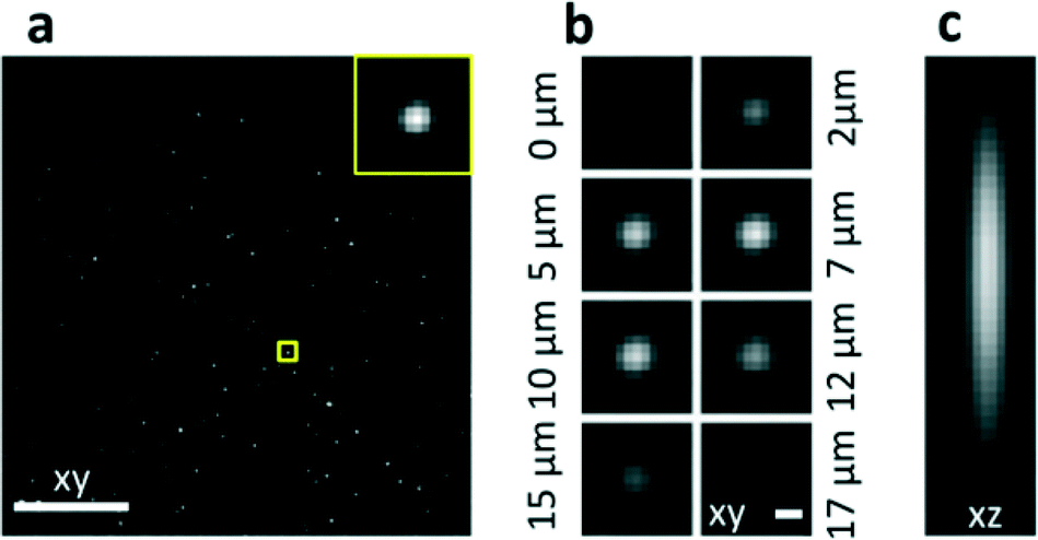 | ||
| Fig. 2 Characterization of the system. (a) Images of nanobeads slowly flowing through the detection plane xy. Maximum Intensity Projection of 100 acquired frames. (b) Transverse PSF: images of a single nanobead transiting through the light sheet, shown at different time points corresponding to 2.1 μm spacing. (c) Axial PSF: lateral view of the central plane of a stack of images acquired as in (a). Scale bar, 100 μm (a) and 1 μm (b and c). | ||
Fixed tissue spheroids expressing a histone H2B fluorescent nuclear reporter protein (mCherry) were allowed to flow in the microchannel at a constant speed and their sections were acquired while passing through the light sheet (Movie 2). A LabVIEW (National Instruments) program was implemented to control the pumping system in order to deliver the samples to the chip, scan them through the light sheet at a constant speed and continuously acquire the images while the sample was moving at a speed of 20 μm s−1. The time used to acquire a single image was typically 50 ms. The quality of the optical sections (Fig. 3a–c), maintained at various depths in the sample (Fig. S5†) allows for clear recognition of the different nuclei, cells segmentation and cell counting (see Fig. S6†). Using these images we have been able to obtain the Maximum Intensity Projection (MIP) of the spheroids (Fig. 3d), and the 3D rendering of the acquired stack, which can be rotated over 360° to show all the details of the spheroid (as shown in Movie S3†). Both these methods demonstrate the 3D reconstruction capabilities of the device, which was partly possible thanks to the optical clearing effect of the index matching liquid (TDE). The imaging detail is sufficient to observe cell mitosis in 3D in several locations of the spheroid (Fig. 3c and Fig. S7†) as well as chromosome condensation in the nucleus, which is preliminary to cell mitosis (Fig 3e). We conclude that the image quality in our integrated-SPIM device is sufficient to image the entire spheroid at subcellular resolution.
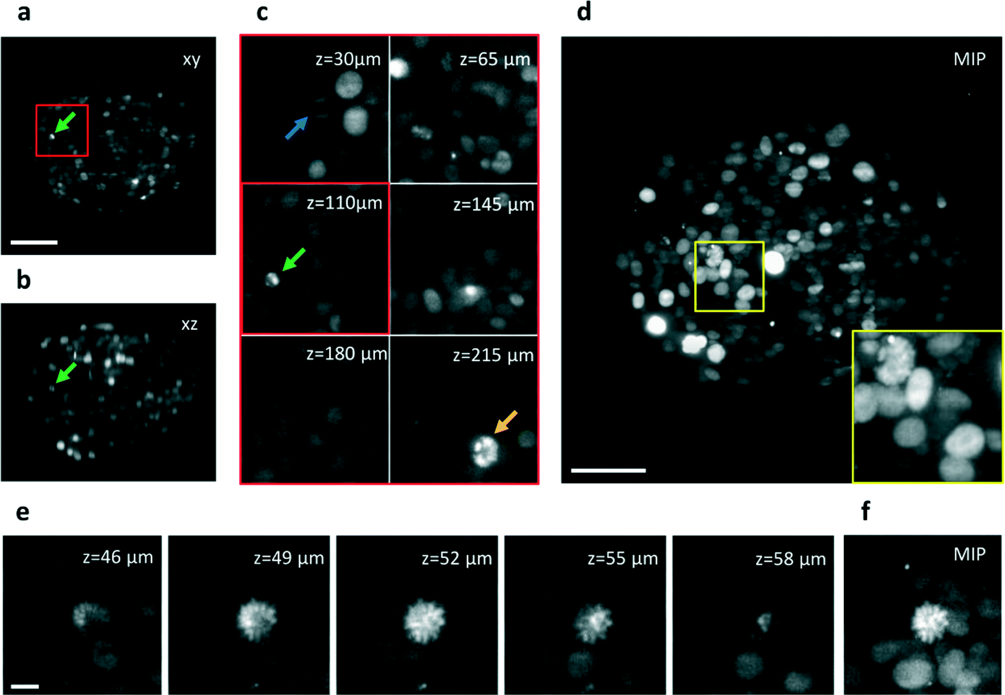 | ||
| Fig. 3 Automatic imaging of cellular spheroids. (a) Single section of a H2B-mCherry expressing spheroid acquired while crossing the light sheet at ca. 20 μm s−1. The image plane is indicated with xy. The section corresponds to a position of z = 110 μm in depth into the sample. (b) Transverse view of the sample in (a) obtained after the acquisition of 150 frames (c) Details of the spheroid at different depths into the sample. Arrows indicate three mitotic cells, also shown in Fig. S7.† (d) Maximum Intensity Projection of the acquired stack of 150 frames. (e) Details of single sections of a second spheroid acquired at various depths, shown with 3 μm steps, which indicate the good sectioning capability of the setup. (f) Maximum Intensity Projection of the stack shown in (e). A mitotic nucleus can be identified in the center of the image by the high fluorescence intensity of the condensed chromosomes shape. Scale bar, 100 μm (a–d) and 10 μm (e). | ||
For high-throughput imaging, the sample was allowed to flow at a velocity of 200 μm s−1 through the light sheet, and a CMOS Camera (GS3, Pointgrey) running at 87 Hz was used during the acquisition, because of the higher frame rate available with respect to the CCD Camera. Indeed, for a good 3D sample reconstruction it is important to acquire a number of images sufficiently high for a good sampling of the object; for this reason the frame rate acquisition has to be chosen accordingly to the sample velocity. In order to save memory space, the imaging camera was triggered by a fluorescence signal (integrated over the whole imaging window) overcoming a suitable threshold.
The section recording then continued until the fluorescence signal decreased below the same threshold. The spheroids were forced to flow one by one through the light sheet, due to their size compared to that of the microchannel and were automatically recorded in less than 2 seconds per sample, which permits to acquire up to 30 samples per minute depending on the sample concentration (Movie 4). An example of a high-throughput acquisition is shown in Fig. 4a and b where a single section of different spheroids and their maximum intensity projections are reported. Highly reproducible quality of the imaging is demonstrated in all samples with measurement times that are orders of magnitude shorter than those required in regular light sheet microscopes, where sequential sample preparation and mounting is performed. The spheroids have been analyzed all in the same run with a fully automatic process.
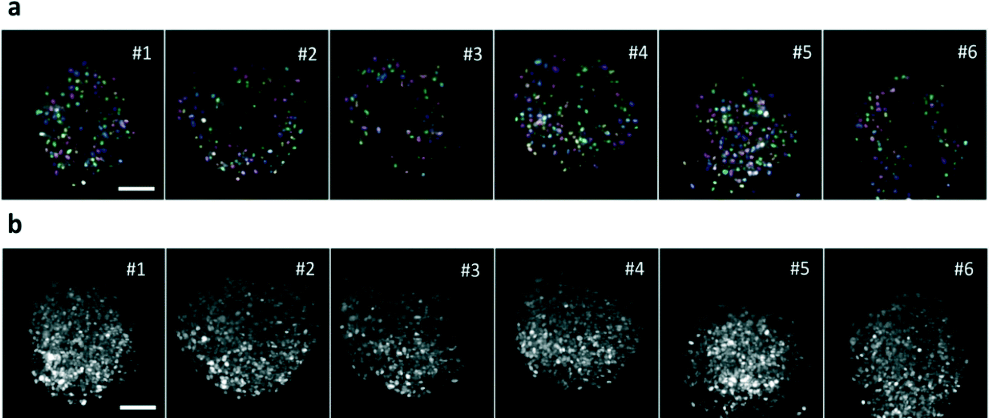 | ||
| Fig. 4 High-throughput imaging. (a) Single plane of 6 different H2B-mCherry expressing spheroids, acquired at 70 μm depth in a high-throughput mode, at 87 Hz, with the sample moving at 200 μm s−1. Segmented nuclei are indicated in different colors. (b) Maximum Intensity Projections of the samples. Scale bar, 100 μm. | ||
Quantitative analysis of the high-throughput data is possible, enabling consistent statistical studies on e.g. fluorescence intensity of single cells (see text and Fig. S8†) or volume and shape of the samples (see Fig. S9†). To further characterize our system, we measured the signal to noise ratio (SNR) that we obtained using the two cameras. In the case of the CCD camera, the signal was sufficient to saturate the 11 bit dynamic of the camera, without using any gain. With these conditions, the SNR is limited by the full well capacity divided by the camera noise and is equal to 30 dB. As far as the CMOS camera is concerned, a shorter acquisition time was used; the SNR of the images calculated considering the background of the image as noise, and the fluorescence of the spheroid as signal, averaged over 20 distinct images, is equal to 21.2 dB. These values, combined with the discussed capability of quantifying useful sample information, such as the number of nuclei, their intensity and the sample volume, demonstrate the potential of our high-throughput integrated approach.
Conclusions
Our device is the first demonstration of a high-throughput, on-chip light sheet microscope that can upgrade any standard fluorescence microscope to a SPIM system. This device enables the acquisition of high-resolution three-dimensional images of large multicellular spheroids at a rate of 30 samples min−1, allowing continuous operation without any alignment requirement. This optofluidic device gives access to SPIM analyses to non-expert end-users, opening the way to automatic and fast screening of a high number of samples at a subcellular resolution. The chip allows for a double-sided detection (two opposite microscope objective could be mounted to reduce the scattering effect in the sample). Multiple-side illumination28 could be also integrated by fabricating two (or more) cylindrical lenses around the channel. Devices tailored for different sample sizes can be foreseen opening the door to high-throughput SPIM imaging of samples ranging from single cells to millimeter-sized specimens. FLM technology allows the combination of the present device with previously demonstrated ones for sample manipulation and sorting,29 enabling the extraction of subpopulations on the basis of real-time processing of the acquired images and offering new possibilities for drug screening and pharmaceutical studies.Acknowledgements
The research leading to these results has received funding from Laserlab-Europe (EU-H2020 654148). We thank C. Lorenzo (ITAV – CNRS, Toulouse) for proving the tumor spheroids and N. Bellini for useful discussions.Notes and references
- J. Huisken, J. Swoger, F. Del Bene, J. Wittbrodt and E. H. Stelzer, Science, 2004, 305, 1007 CrossRef CAS PubMed.
- P. A. Santi, J. Histochem. Cytochem., 2011, 59(2), 129 CrossRef CAS PubMed.
- E. G. Reynaud, U. Kržič, K. Greger and E. H. K. Stelzer, Light sheet-based fluorescence microscopy: more dimensions, more photons, and less photodamage, HFSP Journal, 2008, 2(5), 266–275 CrossRef PubMed.
- C. J. Engelbrecht and E. H. Stelzer, Resolution enhancement in a light-sheet-based microscope (SPIM), Opt. Lett., 2006, 31, 1477–1479 CrossRef PubMed.
- K. Greger, J. Swoger and E. H. K. Stelzer, Rev. Sci. Instrum., 2007, 78(2), 023705 CrossRef CAS PubMed.
- J. N. Buytaert and J. J. Dirckx, Design and quantitative resolution measurements of an optical virtual sectioning three-dimensional imaging technique for biomedical specimens, featuring two-micrometer slicing resolution, J. Biomed. Opt., 2007, 12(1), 014039 CrossRef PubMed.
- A. Costa, A. Candeo, L. Fieramonti, G. Valentini and A. Bassi, PLoS One, 2013, 8 Search PubMed.
- T. A. Planchon, L. Gao, D. E. Milkie, M. W. Davidson, J. A. Galbraith, C. G. Galbraith and E. Betzig, Nat. Methods, 2011, 8(5), 417 CrossRef CAS PubMed.
- F. Pampaloni, N. Ansari and E. H. K. Stelzer, Cell Tissue Res., 2013, 352, 161 CrossRef PubMed.
- C. Lorenzo, C. Frongia, R. Jorand, J. Fehrenbach, P. Weiss, A. Maandhui and V. Lobjois, Cell Div., 2011, 6, 22 CrossRef CAS PubMed.
- P. J. Keller, A. D. Schmidt, J. Wittbrodt and E. H. K. Stelzer, Science, 2008, 322(5904), 1065 CrossRef CAS PubMed.
- F. Pampaloni, B. J. Chang and E. H. K. Stelzer, Cell Tissue Res., 2015, 360(1), 129 CrossRef CAS PubMed.
- Z. W. Zhao, R. Roy, J. C. M. Gebhardt, D. M. Suter, A. R. Chapman and X. S. Xie, Spatial organization of RNA polymerase II inside a mammalian cell nucleus revealed by reflected light-sheet superresolution microscopy, Proc. Natl. Acad. Sci. U. S. A., 2014, 111(2), 681–686 CrossRef CAS PubMed.
- H. Deschout, K. Raemdonck, S. Stremersch, P. Maoddi, G. Mernier, P. Renaud, S. Jiguet, A. Hendrix, M. Bracke, R. Van den Broecke, M. Röding, M. Rudemo, J. Demeester, S. C. De Smedt, F. Strubbe, K. Neyts and K. Braeckmans, Nanoscale, 2013, 6(3), 1741 RSC.
- J. Wu, J. Li and R. K. Y. Chan, Opt. Express, 2013, 21, 14474 CrossRef CAS PubMed.
- R. Regmi, K. Mohan and P. P. Mondal, AIP Adv., 2014, 4(9), 097125 CrossRef.
- T. Bruns, S. Schickinger, R. Wittig and H. Schneckenburger, J. Biomed. Opt., 2012, 17, 101518 CrossRef PubMed.
- B. Patra, Y. S. Peng, C. C. Peng, W. H. Liao, Y. A. Chen, K. H. Lin and C. H. Lee, Biomicrofluidics, 2014, 8, 052109 CrossRef PubMed.
- R. Osellame, H. J. Hoekstra, G. Cerullo and M. Pollnau, Laser Photonics Rev., 2011, 5, 442 CrossRef CAS.
- R. Gattass and E. Mazur, Nat. Photonics, 2008, 2, 219 CrossRef CAS.
- R. Osellame, V. Maselli, R. Martinez Vazquez, R. Ramponi and G. Cerullo, Appl. Phys. Lett., 2007, 90, 231118 CrossRef.
- S. Ho, P. R. Herman and J. S. Aitchison, Appl. Phys. A: Mater. Sci. Process., 2012, 106, 5–13 CrossRef CAS.
- T. Yang, P. Paiè, G. Nava, F. Bragheri, R. Martinez Vazquez, P. Minzioni, M. Veglione, M. Di Tano, C. Mondello, R. Osellame and I. Cristiani, An integrated optofluidic device for single-cell sorting driven by mechanical properties, Lab Chip, 2015, 15, 1262–1266 RSC.
- E. Fennema, N. Rivron, J. Rouwkema, C. van Blitterswijk and J. de Boer, Trends Biotechnol., 2013, 31(2), 108 CrossRef CAS PubMed.
- P. J. Verveer, J. Swoger, F. Pampaloni, K. Greger, M. Marcello and E. H. K. Stelzer, Nat. Methods, 2007, 4, 311 CAS.
- H. F. Chan, et al. , Sci. Rep., 2013, 3, 3462 Search PubMed.
- T. Staudt, M. C. Lang, R. Medda, J. Engelhardt and S. Hell, Microsc. Res. Tech., 2006, 70, 1 CrossRef PubMed.
- J. Huisken and D. Y. R. Stainier, Opt. Lett., 2007, 32(17), 2608 CrossRef PubMed.
- F. Bragheri, P. Minzioni, R. Martinez Vazquez, N. Bellini, P. Paiè, C. Mondello, R. Ramponi, I. Cristiani and R. Osellame, Lab Chip, 2012, 12, 3779 RSC.
Footnotes |
| † Electronic supplementary information (ESI) available. See DOI: 10.1039/c6lc00084c |
| ‡ These authors contributed equally to the work. |
| This journal is © The Royal Society of Chemistry 2016 |