
Active droplet generation in microfluidics
Zhuang Zhi
Chong
a,
Say Hwa
Tan
 *b,
Alfonso M.
Gañán-Calvo
*c,
Shu Beng
Tor
a,
Ngiap Hiang
Loh
a and
Nam-Trung
Nguyen
*b
*b,
Alfonso M.
Gañán-Calvo
*c,
Shu Beng
Tor
a,
Ngiap Hiang
Loh
a and
Nam-Trung
Nguyen
*b
aSchool of Mechanical and Aerospace Engineering, Nanyang Technological University, 50 Nanyang Avenue, 639798, Singapore
bQueensland Micro- and Nanotechnology Centre, Griffith University, 170 Kessels Road QLD 4111, Brisbane, Australia. E-mail: sayhwa.tan@griffith.edu.au; nam-trung.nguyen@griffith.edu.au
cDepto. de Ingeniería Aeroespacial y Mecánica de Fluidos, Universidad de Sevilla, E-41092 Sevilla, Spain. E-mail: amgc@us.es
First published on 27th October 2015
Abstract
The reliable generation of micron-sized droplets is an important process for various applications in droplet-based microfluidics. The generated droplets work as a self-contained reaction platform in droplet-based lab-on-a-chip systems. With the maturity of this platform technology, sophisticated and delicate control of the droplet generation process is needed to address increasingly complex applications. This review presents the state of the art of active droplet generation concepts, which are categorized according to the nature of the induced energy. At the liquid/liquid interface, an energy imbalance leads to instability and droplet breakup.
 Zhuang Zhi Chong | Chong Zhuang Zhi received his bachelor's degree in Mechanical Engineering from Nanyang Technological University, Singapore in 2011. He is currently a PhD candidate in the School of Mechanical and Aerospace Engineering, Nanyang Technological University, Singapore. His research interest is focused on droplet/bubble generation and video processing measurement in microfluidics. |
 Say Hwa Tan | Dr. Say Hwa Tan is an early career researcher in Queensland Micro-and Nanotechnology Centre, Griffith University, Australia. He received his PhD in 2014 from the Georg-August-Universität Göttingen and Max Planck Institute for Dynamics and Self-organization (MPI-DS), Germany. During his PhD, he patented a new technology to actively control the size of microdroplets using an AC electric field. The Microfluidic Jukebox was developed using this technology. His research has pioneered different approaches to manipulate droplets and bubbles using thermal, magnetic, acoustic and electric energy. Dr. Tan has published over 20 journal papers, 2 patents and 1 book chapter on microfluidics. |
 Alfonso M. Gañán-Calvo | Alfonso M. Ganan-Calvo is a professor and the chair of Fluid Mechanics at the University of Seville, Spain, receiving his PhD degree there in 1989. He was postdoctoral researcher at the University of Southern California and a visiting professor at the University of California, San Diego, USA. He is also the president of Ingeniatrics, Spain, has published over 110 journal papers, and filed over 150 patents. He is a recipient of the National Prize of Research “Juan de la Cierva” of Spain (2010), and a fellow of the American Physical Society since 2012. He invented Flow Focusing in 1994 and Flow Blurring in 2004, and filed patents on those technologies during the periods 1996–2002 and 2004–2007, respectively. |
 Shu Beng Tor | Dr. Tor Shu Beng is an associate professor of the School of Mechanical and Aerospace Engineering, NTU. He is also the Programme Director for the Marine and Offshore, Singapore Centre for 3D Printing. He served as a faculty fellow in Singapore MIT Alliance from 2000–2013 and the course coordinator of the SMA program on Manufacturing Systems and Technology (MST) from 2000–2010. He has also served as the Head of the Manufacturing Engineering Division and as the Associate Chair (Academic) of the School before July 2011. His research focuses on micro-replication processes, tooling for micro-replication and most recently additive manufacturing. |
 Ngiap Hiang Loh | Dr. Loh Ngiap Hiang is an Associate Professor in the School of Mechanical & Aerospace Engineering, Nanyang Technological University (NTU) in Singapore. Her research interests focus primarily on power injection molding, micro powder injection molding and powder-related processes. |
 Nam-Trung Nguyen | Nam-Trung Nguyen is a professor and the director of Queensland Micro- and Nanotechnology Centre, Griffith University, Australia. He received his Dipl-Ing, Dr-Ing and Dr-Ing Habil degrees from the Chemnitz University of Technology, Germany, in 1993, 1997 and 2004, respectively. He was a postdoctoral research engineer at the Berkeley Sensor and Actuator Center, University of California, Berkeley, USA. From 1999 to 2013, he was a research fellow, assistant professor and associate professor at Nanyang Technological University, Singapore. Dr. Nguyen has published over 220 journal papers and several books on microfluidics and nanofluidics. |
1. Introduction
In a few decades from now, microfluidics could be the key technology for gathering extensive information from chemical and biochemical analysis, diagnosis and therapeutics. However, microfluidics currently cannot match the significance of microelectronics in our everyday life. The early high expectations1,2 on microfluidics technology have not been met. Table 1 lists the present (as of June 2015) annual growth rate of publications related to microfluidics using different keywords. The current overall growth rate of approximately 2% is significantly lower than the annual 20.5% during the period of 1997–2005. Considering the worldwide growth rate of scientific publications of about 2%, microfluidics research in general may have reached its saturation. Whitesides elaborated some reasons for this trend.3| Wording | Annual growth rate (%) |
|---|---|
| Graphene | 16.10% |
| “Flow chemistry” | 10.64% |
| Microfluidics* & “flow focusing” | 4.09% |
| “Flow focusing” | 4.08% |
| Microfluidics* & drop* | 3.98% |
| Microfluidics* & drop* & control* | 3.18% |
| Microfluidics* & T-junction | 2.16% |
| Microfluidic* | 2.05% |
| T-junction | 1.99% |
| Microfluidics* & *pump* | −0.30% |
| Microfluidics* & valve* | −1.13% |
| Microfluidic* & “drop* form*” | −5.08% |
| “Drop* form*” | −13.16% |
| (All articles) | 2.01% |
While microfluidic designs in nature are three-dimensional (3D), the majority of microfluidic systems are two-dimensional (2D) due to the use of photolithography4–7 inherited from microelectronics technology. The current saturation level of publication output may be caused by the 2D limitations for the physics of flows involved such as closed flows, low Reynolds number, strong surface interactions, limited maximum pressures and sensitivity to clogging.
One possible way to create a 3D environment in microfluidics is the intelligent generation of droplets in a 2D microfluidic device, followed by or merged with a more general 3D design. This merging would generally demand a strict control over the size and time associated with the generated droplet. The formation or generation process of droplets illustrates the complexity of microfluidic handling. The relatively small forces related to interfacial tension make the droplet formation process highly nonlinear and sensitive to external disturbance. Over the last two decades, droplet formation under a limited set of non-dimensional parameters has been one of the classical hot topics of fluid physics and consequently of microfluidics (Fig. 1).7–18 The knowledge about the fundamental physics of droplet formation has reached a sufficient level of maturity. Fig. 1 indicates that the number of papers with “droplet formation” has decreased in favor of the more direct applications of droplet-based microfluidics.
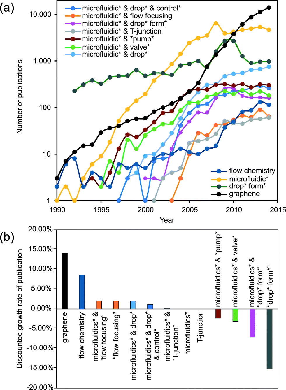 | ||
| Fig. 1 (a) Evolution of publication number per year using primarily (in title, abstract or keywords) the indicated words. The global publication output is currently about 40 million papers, with an approximately constant growth rate of about 2.5%, maintained since 1975. (b) Growth rate of publications per year discounted with the annual growth rate of global publications (extracted from Scopus on 8th of June, 2015). | ||
To form a droplet from a continuous liquid phase, energy needs to be introduced to the droplet surface so that some of the energy is converted into surface energy. That energy may come from the hydrodynamic pressure of the flow without any external input, which is known as passive control. Active control is achieved if external energy is locally added to the droplet formation process. The two most widely used configurations for passive droplet formation are the T-junction6,12,19 and the flow focusing junction.7,20–24 The flow focusing junction can be further categorized as cross-junction (planar25,26 or axisymmetric22,27) and genuine flow focusing. Genuine flow focusing discharges the droplets into an open environment, or a significantly wider channel.7,20,28 Historically, the first flow focusing configuration proposed was symmetric,20,29 even though the original patent30 covered both axisymmetric and planar configurations. Stone's group7 performed a simple but remarkably successful translation of this concept into a planar microdevice.
In both configurations, droplet formation can be controlled passively by varying the flow rate or the applied pressure.31 Syringe pumps are usually employed to drive the flow with a controllable flow rate, while a gravity-based pressure unit or a pressure controller is used for pressure driven flows. The major drawback of passive control is the slow response time in the order of seconds or even minutes.32 The long response time comes from the relatively large fluidic resistance of the tubing and the fluidic capacitance caused by the compressibility of the liquid or the channel material.33,34 The only way to achieve a specific droplet size with preset flow rates or pressures is by adjusting the liquid properties and channel geometries.
A significant number of review papers on droplet-based microfluidics exist in the literature. These previous reviews discussed device fabrication,35 production and/or manipulation of droplets,35–42 fusion or fission.35,37–40 To our best knowledge, there is no review paper dedicated exclusively to the active control of droplet generation. Though a book chapter briefly discussed the active control of droplet formation,43 it was limited to thermal and magnetic control only. Christopher et al.36 devoted a section discussing active control methods using pneumatic/hydraulic valves, piezoelectric actuation and electric field. Teh et al.37 briefly mentioned pneumatic valves and electrowetting in their review. Baroud's review38 has a small section on control using a laser, a pneumatic/hydraulic valve and a heater. Seemann et al.35 discussed the “active elements” in droplet generation devices such as pneumatic/hydraulic valves, heaters, and piezoelectric actuators. Chen's review paper40 mentioned pneumatic pressure, as well as optical and electric methods. Song et al.41 discussed thermal control and the chopping method in their review. Theberge et al.39 and Zhao et al.42 just listed active methods such as electrical, mechanical and thermal approaches in their review.
In the present review, we will focus specifically on closed-channel microfluidic systems.11 The length scales of the characteristic flow channels are smaller than one millimeter.33 We only consider the flow of two phases. The liquid phase of the droplets is the dispersed phase, and the surrounding liquid is the continuous phase. The review discusses (i) active control methods according to the type of external energy for activation, (ii) the fundamental mechanism to introduce such energy, (iii) the typical implementations of each method, (iv) the comparison among alternative methods in terms of efficiency, speed, compactness, robustness and reproducibility, and (v) the perspectives on their improvements. While 3D or open microfluidic designs use a wide variety of active methods (often inherited from other fields), those cannot be immediately imported, or not applicable at all in closed channel microfluidics.
2. Electrical control
Electric energy can be used to manipulate droplet generation. The combination of both mechanical and electric focusing forces at the microscale was initially proposed in a 3D configuration.49,50 That concept was subsequently incorporated in a 2D or planar microfluidic configuration by Anna et al.7 and Link et al.,44 following the same path as the original 3D flow focusing.20,51 Combining forces of completely different origins requires special consideration for the geometry and location of the electrodes. The electrodes should provide a main electric field component not only aligned with the mechanical force, but also having its maximum located around the same (focusing) region of the force.52 The electrodes integrated into the system could either be in contact with the liquids or separated by a dielectric material to prevent electrode fouling.Electrical control of droplet generation can be categorized according to the type of current applied to the electrodes (Fig. 2). For direct current (DC) control, the magnitude of voltage remains constant throughout the application of the current. For alternating current (AC) control, the voltage fluctuates with a frequency that is different than that of droplet generation. For high-frequency AC control, the frequency of the control signal is much higher than that of droplet generation. Therefore, the droplet generation frequency determines the characteristic time of the system.
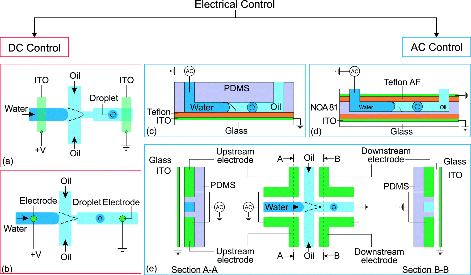 | ||
| Fig. 2 Classification of electrical control approaches. (a) Application of direct current on flow focusing configuration. The indium tin oxide (ITO) is patterned on a glass slide before being bonded to a PDMS device.44 (b) Flow focusing configuration with electrodes brought into contact with the fluids via insertion through PDMS.45 (c) Flow focusing device with EWOD control.46 (d) Flow focusing device fabricated using NOA 81 with EWOD control. An extra ITO electrode is placed on top of the channel to increase the effect of EWOD.47 (e) Flow focusing device fabricated with electrodes and its electrical connections. The dotted lines illustrate the changes after activation of the electrical control.25,48 | ||
2.1 Direct current
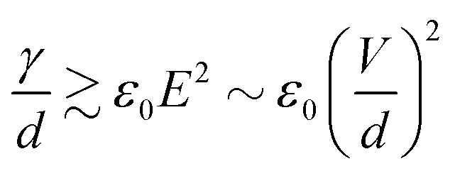
Link et al.44 employed a DC voltage to control the droplet formation in a microfluidic setup (Fig. 2(a)). The planar flow focusing device had two electrodes made of indium tin oxide (ITO). The ITO electrodes were patterned on top of a glass slide before being bonded53 to the PDMS part with microchannels. These electrodes had a direct contact with the liquids inside the channel. With an appropriate electrode design, the process of droplet formation changes upon application of a high voltage to a relatively conducting (or leaky dielectric54) liquid stream (Fig. 2(a)). Water as a paradigmatic leaky dielectric has been extensively used in microfluidics. Water allows its free charges to quickly migrate in opposite directions under the applied electric field, until they hit the water–oil interface, where they accumulate.55 Under a fixed set of flow rates, the droplet size decreases with increasing applied voltage, as a result of charge accumulation at the interfaces. The droplet volume can decrease by three orders of magnitude by increasing the voltage alone. In tangible terms, increasing the applied electric field E ~ V/d demands an increase of interfacial area per unit volume 1/d to accommodate the extra induced charges, where V is the applied voltage and 1/d is the characteristic surface curvature or the inverse of droplet size. This phenomenon can also be understood in terms of a simple capacitor model. The droplet interface between the conductive water stream and the isolating oil stream acts as a capacitor, where the surface charge q ~ ε0E increases with the applied voltage. A larger surface area per unit volume, or overall surface curvature, leads to an increase in surface energy associated with surface tension. The normal stress balance at the water–oil interface is| γC = p + {ε0E0,n2 + (εi − ε0)Ei,n2 − εiEs2} | (1) |
 | (2) |
However, as V increases, the electric forces increase faster (roughly as d−2) than the surface tension (as d−2), leading to instability, surface disruption, and ejection of the droplets. In other words, instability sets in when the local symmetry (balance) provided by eqn (1) is no longer possible. The increasing electric force decreases the break up time  , thus forming smaller droplets under constant flow rates. If the applied voltage is too large, the interface anchored at the outlet and the issuing droplet becomes highly charged at pinch off. The charge causes both of them to repel each other, promoting the droplet formation instability.
Electric control with direct current does not require moving parts. Besides, as charging and discharging of the interface can be quickly performed, the response time is reduced down to 10 μs.44 However, electrode fouling is the main drawback of this technique. The upstream electrode is constantly in contact with the dispersed phase, while the downstream electrode only makes contact as the highly charged water droplets pass by. The electrode in contact with water is susceptible to fouling and could affect the reliability of the system.56 Furthermore, the droplets produced by this approach are charged, and may not be suitable for sensitive chemical or biological samples.
The above concept was continued by Kim et al. without the ITO electrode.45 The electrodes are in contact with the fluids through a metal wire directly inserted through the PDMS. Fig. 2(b) shows this setup. Similar to Link's result, the droplet size decreases with increasing applied voltage. However, instead of becoming an unstable stream when the applied voltage is too large, the dispersed stream of this setup forms a jet connecting the stream source to the ground electrode located downstream. Fine droplets with a diameter less than 1 μm were formed at a relatively low flow rate ratio between the dispersed and the continuous phase. The droplets are claimed to be formed from the tip of a Taylor cone, a cone-shaped interface with a 49.3° half-angle apex balanced by electrostatic force and surface tension.57 However, the Taylor cone formed under this setup could only be kept stable for about a minute due to the pulsation exerted by the syringe pump run at a low flow rate.
2.2 Alternating current
In contrast to DC control, the electrodes of this approach are connected to an alternating current (AC) voltage. In terms of frequency, electric control with AC voltage can be further categorized into the two groups of low-frequency and high-frequency control. A frequency lower than the frequency of droplet generation is considered as low. A frequency above the droplet generation frequency is considered high. At low-frequency control, droplet generation is asynchronous and out of phase with the applied AC voltage, causing differences in the charge of individual droplets. The low-frequency approach was attempted by Kim to improve the repeatability of Taylor cone formation.45 A pulse of 200 ms, with about 25 ms to ramp up/down, and an amplitude between 0 and 2000 V were applied to the electrodes. The Taylor cone is formed once per pulse.Later, He et al. used a setup similar to Kim's to investigate the response of droplet formation under low-frequency AC control.58 In this work, the triangular AC signal had a frequency of 10 Hz and an amplitude of 2 kV. Interestingly, the change in the droplet size was independent of the polarity of the voltage. However, that change exhibited a hysteresis effect with the applied voltage. The droplet size decreased rapidly during the initial stage of the voltage ramp up. The droplet size then reached its minimum at about the middle of the ramp-up stage, before increasing slowly for the second half of the ramp-up stage. The droplet size continued to increase gradually for the whole ramp-down stage before restoring the original size near the end of the ramp-down stage. This phenomenon is related to the relaxation of flow rate oscillation, which can be explained by a model analogous to an RC electric circuit with varying resistance.58
In high-frequency control, the average applied voltage during the generation of each droplet is approximately zero. In this approach, the droplet size is tuned by the frequency and the root-mean-square amplitude of the AC voltage. The electrowetting phenomenon can be observed in an electrolyte droplet on top of an electrode. The contact angle decreases upon application of a voltage across the electrolyte and the electrode. However, this phenomenon is typically only applicable up to about a hundred millivolts, before the occurrence of electrolysis.59 The electrolysis problem is addressed by having a thin insulating film between the electrode and the electrolyte.60 This configuration, also known as electrowetting on dielectric (EWOD), allows the application of a large voltage that further reduces the contact angle. Although both DC and AC can be used for EWOD, AC is generally superior as it reduces the contact angle hysteresis.61 To our best knowledge, manipulation of droplet generation based on EWOD has been reported with AC voltage only. Malloggi et al. introduced the use of EWOD to control droplet generation on a flow focusing device.46 The device consists of a PDMS part with flow focusing channels attached to an ITO glass pre-coated with a ~4 μm thick Teflon film (Fig. 2(c)). An AC voltage (10 kHz, 0–170 Vrms) was applied on the aqueous phase through a thin wire while the ITO is grounded. A NaCl solution was used to enhance the conductivity of the aqueous phase. Both liquid phases were delivered individually into the device using hydrostatic heads.
The effect of electrowetting on the oil–water interface is indicated through the critical external water pressure  required to sustain the interface at the flow focusing junction at a given external oil pressure P0. The water pressure
  decreases with increasing voltage Vrms:
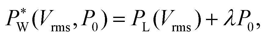 | (3) |
 needs to exceed the sum of PL(U) and λP0 before droplets are generated.
In eqn (1), the local surface curvature is expressed as 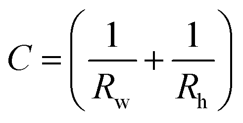 , where Rw and Rh are the two radii of curvature of the surface. In an analogous way to DC control, when an AC voltage is applied to the aqueous phase, the contact angle on the Teflon film decreases and Rh increases. In addition, increasing voltage Vrms may lead to an increase in electric stress on the oil–water interface. Both effects force a decrease in water pressure
  to maintain the balance (eqn (3)). With constant Rw and γ, PL(Vrms) decreases under the applied AC voltage. This model explains well the decrease in
  with increasing Vrms in the experiment. Under a constant set of pressures, the droplet size increases with increasing voltage.62 This effect is similar to an increase in the water flow rate owing to a smaller hydrostatic pressure at the outlet of the water channel. Since shear viscous forces dominate in the oil flow, the ratio between the viscous force and the electrostatic force on the water surface grows,62 causing its destabilization. Mallogi et al. also reported the on-demand generation of droplets using the same setup by applying AC pulses. The droplet starts to form above a critical pulse width. The droplet volume could be tuned by the pulse width.
Active control using EWOD does not need a counter-electrode in contact with the fluids flowing at the downstream channel. Furthermore, the applied voltage is much smaller than that needed for DC control. The lower voltage is gentler for the electrode that is in contact with the aqueous stream. However, the effectiveness of EWOD reduces dramatically if the interfacial tension is reduced by addition of surfactants such as Span 80 and Triton X-100.62
Gu et al.63 reported a similar approach but using a much smaller orifice.64 Instead of driving the oil flow using hydrostatic pressure, a syringe pump was used. A regime called tip-streaming was observed at low water pressure. The droplets formed in this regime had diameters between 1–2 μm and had a high spatial density. This phenomenon is similar to that caused by surfactant accumulation near the meniscus tip, as described by Anna and Mayer.65 Gu et al. used a master parametric map64 to show that upon increasing the applied voltage over a critical value from this regime, a “conical spray” regime occurred. In this regime, the droplets repel each other and spread out upon exiting the orifice. Interestingly, in this regime, the average droplet size increases with increasing voltage. The observed phenomenon might be related to the interplay between the extremely short relaxation timescale of the surfactant molecules at the interface tip and the applied frequency. However, in the dripping regime, the droplet size decreases with increasing voltage, as predicted by eqn (1).
In terms of device material, Gu et al. made the EWOD device using Norland Optical Adhesive (NOA).47 This material has a higher stiffness than PDMS, which enables the fabrication of channels with dimensions down to a few micrometers with a small aspect ratio. Furthermore, the material is compatible with a wider range of oils as compared to PDMS. Fig. 2(d) shows that the effectiveness of electrowetting is further increased by having two ITO electrodes located on the top and the bottom of the microchannel. Before using the device, the microchannels underwent salinization treatment to make them hydrophobic and more sensitive in electrowetting control. In this setup, both oil and water flow rates are driven by syringe pumps. Compared to PDMS devices, EWOD control on NOA devices is more stable. As two electrodes are located on the top and the bottom of the channel, the droplet size is more sensitive to the change in voltage.
EWOD-based control requires one of the electrodes to be in contact with the aqueous liquid. Thus, the electrode is still susceptible to fouling. The response of EWOD to AC voltage starts to deteriorate upon reaching a critical frequency at around 1 kHz for DI water with low conductivity.66 The lower AC frequency may limit the production rate of monodisperse droplets. To address this problem, Tan et al. suggested a design different from the typical EWOD setup, where all the electrodes are not in contact with the liquids.25,48 This approach allows a higher frequency of up to 50 kHz to control the generation of low conductivity DI water droplets. Fig. 2(e) illustrates the design of the planar flow focusing device. There are four electrodes, two upstream and two downstream, around the junction of the flow channel. The device is bonded to an ITO-coated glass. The ITO side is facing outward and is not in contact with the microfluidic channels. The electrodes were made by filling the microfluidic channels with indium using the technique called microsolidics.67 The live terminal of the AC power supply is connected to the upstream electrode pair while the downstream electrode pair and the ITO film are grounded.
Under a constant set of flow rates, the droplet formation regime changes upon application of the AC voltage. Generally, the droplet size decreases with increasing voltage. The droplet generation process also depends on the frequency and the conductivity of the aqueous phase. The initial dripping regime changes to the jetting regime when a high enough AC frequency is applied while using an aqueous phase with a low enough conductivity. The dripping regime remains unchanged at a low AC frequency and high conductivity. Interestingly, the droplet formation is unstable at the intermediate range of AC frequency and conductivity.
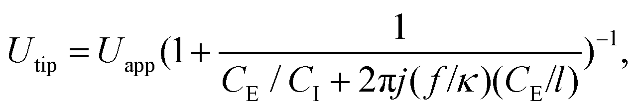
Experimental results suggest that the droplet size at the dripping regime was related to the voltage difference between the oil–water interface and the downstream electrodes. However, as the electrodes are not in contact with the liquids and measuring the voltage at the interface is difficult, the RMS voltage at the tip (Utip) of the interface can be deduced using an RC circuit model. From that model, one obtains the equation,
 | (4) |
| Source | Type of current | Flow channel geometrya | Fluidsb | Notes |
|---|---|---|---|---|
| a H – height in μm; W – width in μm. b C – continuous phase; D – dispersed phase. | ||||
| Ref. 44 | Direct current | Flow focusing: | C = oil | Voltage ≤ 800 V |
| Orifice W = 30 | D = water | *Channel H is not stated | ||
| Ref. 45 | Direct current, low-frequency pulse current | Flow focusing: | C = mineral oil + 6% Span 80 | Voltage ≤ 2000 V |
| H = 61.4, W = 100 | D = distilled water | Pulse frequency = 5 Hz | ||
| Orifice W = 50 | ||||
| Downstream W = 150 | ||||
| Ref. 58 | Low-frequency ac | Flow focusing: | C = mineral oil (30 cP) + 6% Span 80 | Triangular ac voltage from −2 to 2 kV, 10 Hz |
| H = 50, W = 92.7, 83.6 | D = distilled water | |||
| Orifice W = 46.3 | ||||
| Downstream W = 140 | ||||
| Ref. 46 | High-frequency ac | Flow focusing: | C = mineral oil (30 mPa s) | 10 kHz AC source |
| H = 55, 115, 160, 190 | D = DI water + NaCl (1 S m−1) | Voltage ≤ 170 Vrms | ||
| W = 390 | ||||
| Ref. 62 | High-frequency ac | Flow focusing: | C = mineral oil (30 mPa s) | 10 kHz AC source |
| H = 100, W = 390 | D = DI water + NaCl (1 S m−1) | Voltage ≤ 150 Vrms | ||
| For experiments with surfactants, either D + 0.1% Triton X-100 or C + 0.1% Span 80 | ||||
| Ref. 63 | High-frequency ac | Flow focusing: | C = mineral oil + 3% Span 80 | 10 kHz AC source |
| H = 50, W = 100 | D = DI water + NaCl (0.5 S m−1) | Voltage ≤ 55 Vrms | ||
| Orifice W = 50 | ||||
| Ref. 64 | High-frequency ac | Flow focusing: | C = mineral oil (30 mPa s) + 5% Span 80 | 10 kHz AC source |
| H = 50, W = 200 | D = DI water + NaCl (0.5–0.7 S m−1) | Voltage ≤ 70 Vrms | ||
| Orifice W = 50 | ||||
| Ref. 47 | High-frequency ac | Flow focusing: | C = mineral oil (30 mPa s) + 5% Span 80 | 10 kHz AC source |
| H = 10, W = 100 | D = DI water + NaCl (0.5–0.7 S m−1) | Voltage ≤ 100 Vrms | ||
| Orifice W = 20 | ||||
| Ref. 25, 68 | High-frequency ac | Flow focusing: | C = mineral oil (30 mPa s) + 5% Span 80 | 5–50 kHz AC source |
| H = 35, W = 100 | D = DI water + NaCl (3 × 10⁻⁵–0.3 S m−1) | Voltage ≤ 1000 Vrms | ||
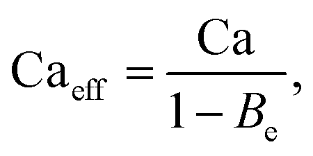
Apart from the electrical model, Tan et al.25 also proposed an electrohydrodynamic model that takes Maxwell stresses into consideration. The model relates the droplet size to an effective capillary number, Caeff:
 | (5) |
3. Thermal control
Thermal control of droplet generation can be categorized into two approaches according to the way the heat is introduced. The first approach utilizes resistive heating at the junction where the droplets are formed. The temperature is controlled by the applied current and feedback from a temperature sensor. The second approach utilizes a focused laser beam to achieve localized heating. Fig. 3 gives an overview of both approaches. Each approach has its own merits and limitations which are discussed as follows.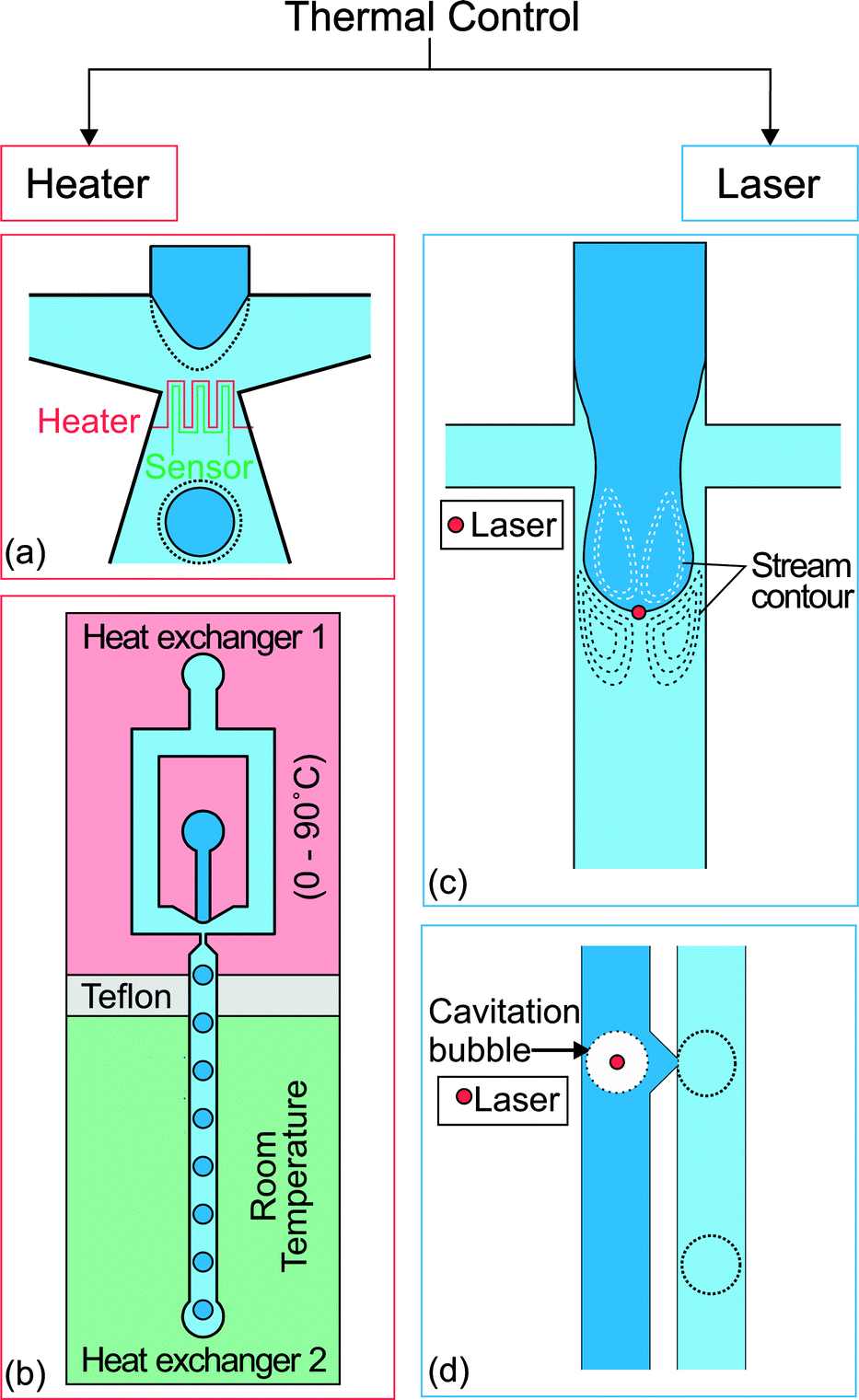 | ||
| Fig. 3 Two approaches for thermal control. (a) Flow focusing geometry with integrated heater and temperature sensor at the orifice of droplet formation.69 (b) A heat exchanger regulates the temperature of the upstream part at a temperature ranging from 0 to 90 °C. The other one keeps the downstream channel at room temperature. Teflon separates the heat exchangers as an insulator.70 (c) Location of the spot applied with localized heat by laser and the stream contour of the Marangoni flow formed around the droplet.71 (d) Droplet produced on demand by creating cavitation bubbles using a high intensity laser. The dotted lines illustrate the changes after activation of the thermal control.72 | ||
The use of resistive heating to manipulate droplet size was first introduced by Nguyen's group.69,73 An integrated microheater and a temperature sensor were used to control both the droplet generation regimes and the droplet size in a microfluidic flow-focusing configuration (Fig. 3(a)).69 The microheater and temperature sensor made of platinum were fabricated using a standard lift-off process. The heater and sensor were insulated from the fluids by a thin PDMS layer to avoid charging of the fluids or possible electrolysis.
Thermal control is based on the temperature dependency of the fluid properties, mainly the viscosity and interfacial tension. For most fluids, viscosity and interfacial tension decrease with increasing temperature. This change is reflected in the change in capillary number Ca. In passive droplet generation, the capillary number is often used to characterize both the diameter and the formation regime of the droplets. The dependency of the normalized droplet diameters for the set of fluids used was expressed as69
 | (6) |
The same group extended the work further to investigate the effect of nanoparticles in different microfluidic geometries and channel heights.74–76 Spherical TiO2 nanoparticles of 15 nm diameter were added to water leading to a reduction of the interfacial tension between water and oil. The reduction was attributed to the Brownian motion of the nanoparticles. The viscosity and interfacial tension decrease almost linearly with increasing temperature. A microfluidic T-junction device with a channel height of about 90 μm, a side channel width of 50 μm and a main channel width of 150 μm was used to investigate the temperature dependence of the droplets formed using both DI water and DI water with nanoparticles as the dispersed phase fluids. Experimental results showed that for the case of DI water, the size of the droplet increases slightly from about 180 to 190 μm. However, with the nanoparticles, the size of the droplet increases from about 220 to 260 μm. The small sensitivity to temperature is caused by the squeezing regime of droplet formation.12 The capillary numbers Ca are 2.8 × 10⁻³ and 4.1 × 10⁻³. With these small Ca numbers, pressure forces dominate over the viscous forces and the size of the droplets depends mainly on the applied flow rate ratio. Therefore, the size of the droplets correlates weakly with the temperature. However, if the channel height is reduced from 90 to 30 μm, the temperature dependence of the droplet size increases due to the larger temperature gradient.75 Interestingly, the temperature dependence of nanofluid droplets changes when a flow focusing configuration is used.76 In this configuration, both DI water and nanofluid exhibit similar characteristics in droplet formation at different temperatures. However, the transition between the droplet formation regimes differs for both fluids. This difference is caused by the complex behavior of nanofluids, which introduces factors such as interfacial slip and Brownian motion.
Heating the entire microfluidic device also provides thermal control. Stan et al.70 placed a microfluidic flow focusing droplet generator on a pair of heat exchangers. One heat exchanger regulates the temperature of the upstream part from 0 to 90 °C, while the other exchanger keeps the downstream channel at room temperature (Fig. 3(b)). Three continuous liquid phases were used, namely Light mineral oil (Sigma Aldrich 330779), Dynalene SF and perfluoroperhydrophenanthrene (PFP, Alfa Aesar L17370). Dynalene SF showed the largest increase in water droplet size. At 70 °C, the droplet volume is 100 times smaller than the original volume at 10 °C. The use of the heat exchanger extended the range of temperature below room temperature and avoided the integration of micrometer and temperature sensors (Table 3).
| Source | Heating element | Flow channel geometrya | Fluidsa | Notesa |
|---|---|---|---|---|
| a C – continuous phase; D – dispersed phase; MO – mineral oil (Sigma M5904); FD – fluorescent dye (Sigma F6377); H – height in μm; W – width in μm; d – diameter in μm; T – temperature in °C; QC – continuous phase flow rate in μL h−1; QD – dispersed phase flow rate in μL h−1; spherical TiO2 has a size of 15 nm; cylindrical TiO2 has a size of 10 × 40 nm. | ||||
| Ref. 69 | Platinum microheater | Flow focusing: | C = MO + 2%w/w Span 80 | T = 25–75 QC = 600, QD = 50: |
| H = 70 | D = DI water + 0.05%w/w FD | +~200% from d = 39.6 QC = 800, QD = 100: | ||
| Orifice W = 45 | +~180% from d = 30.9 | |||
| Channel W = 200 | ||||
| Ref. 74 | Platinum microheater | T-junction: | C = MO + 2%w/w Span 80 | T = 25–56 |
| Q C = 300, QD = 60 | ||||
| H = 90 | D 1 = DI water + 0.1%vol spherical TiO2 + 0.05%w/w FD | +5.6% from d = 180 with D1 | ||
| Main W = 150 | D 2 = DI water + 0.05%w/w FD | +16.1% from d = 224 with D2 | ||
| Side W = 50 | ||||
| Ref. 76 | Platinum microheater | Flow focusing: | C = MO + 2%w/w span 80 | T = 25–45 |
| H = 30 | D 1 = DI water + 0.1%vol spherical TiO2 + 0.05%w/w FD | Q C = 60, QD = 5: | ||
| Orifice W = 45 | D 2 = DI water + 0.05%w/w FD | +97% from d = 61.8 with D1 | ||
| Channel W = 200 | +153% from d = 49.3 with D2 | |||
| Ref. 75 | Platinum microheater | T-junction: | C = MO + 2%w/w Span 80 | T = 25–39 |
| H = 300 & 30 | D 1 = DI water + 0.05%w/w FD | H = 300, QC = 120, QD = 60: | ||
| Main W = 100 | D 2 = DI water + 0.1%vol spherical TiO2 + 0.05%w/w FD | +12% from d = 334 with D1 | ||
| Side W = 50 | D 3 = DI water + 0.1%vol cylindrical TiO2 + 0.05%w/w FD | H = 30, QC = 12, QD = 6: | ||
| +53% from d = 85 with D1 | ||||
| +12% from d = 68 with D2 | ||||
| −15% from d = 106 with D3 | ||||
| Ref. 70 | Heat exchanger | Flow focusing: | C = Dynalene SF | T = 10–70 |
| H = 125 | D = water | Total flow rate = 5.3 mL h−1 | ||
| Orifice W = 40 | Volume increases 100 times of the original volume | |||
| Channel W = 200 | ||||
| Ref. 71 | Argon-ion laser | Cross junction: | C = hexadecane + 2%w/w Span 80 | Laser power = 80 mW |
| H = 30 | D = water + 0.1%w/w fluorescein | Q C = 54, QD = 4.8: | ||
| Main W = 200 | Droplet volume increases about 2 times of the original volume | |||
| Side W = 125 | ||||
| Ref. 72 | Q-switched Nd:YVO4 pulsed laser | Parallel channels with orifice:H = 100, W = 100 | C = Corn oilD = Phosphate-buffered saline buffer |
Q
C = 200–6500, QD = 12![[thin space (1/6-em)]](https://www.rsc.org/images/entities/char_2009.gif) 000–190000: 000–190000: |
| Droplet on demand generation with frequency up to 10000 |
||||
Localized heating at the droplet generation site can be achieved precisely with a focused laser beam. Heating using a laser is more flexible as the position of the focused laser spot can be adjusted easily. Baroud et al. used a focused laser beam to achieve active control of droplet generation.71 An argon-ion laser with a wavelength of 514 nm was focused slightly downstream of a cross junction (Fig. 3(c)). During the droplet generation process, the advancing oil–water interface was blocked at the laser spot (80 mW beam power, 5.2 μm beam waist). The interface continues to advance downstream as the viscous stress grows to overcome the blocking force. As the droplet formation process is delayed under constant flow rates, the droplet size is about 2 times bigger than that produced without heating with a laser.
Tracing the microparticles indicated that a flow is generated around the laser spot. The dashed lines in Fig. 3(c) represent the flow pattern schematically. This flow was induced by the Marangoni effect. Localized heating led to a large temperature gradient and consequently a surface tension gradient at the liquid interface.71 The induced flow is large enough to prevent the interface from advancing downstream. The blocking time is directly proportional to the beam power. For instance with a continuous phase flow rate of Qc = 6 μL h−1 and a dispersed phase flow rate of Qd = 0.18 μL h−1, the blocking time increases from 0.8 to 1.6 s with the laser power increasing from 60 to 80 mW. The focused laser beam has also been applied to merge two droplets, to fuse droplets at formation, to split droplets, and to direct the droplets.77
Extending the concept of laser heating, Park et al. applied a pulse laser on a stable water–oil interface72 to generate water droplets on demand with a valve (Fig. 3(d)). The laser beam caused localized heating with boiling and rapidly created a cavitation bubble. The bubble injects a droplet from the interface into the surrounding oil phase. The flow rates used in that work ranged from 12 to 190 mL h−1 for water and 0.2 to 6.5 mL h−1 for oil. A laser with a high pulse frequency would allow a high droplet generation rate of up to 10000 droplets per second. However, as the process is temperature dependent and repeated laser pulses steadily increase the temperature of the system, the system temperature has to be regulated.
4. Magnetic control
A liquid may exhibit a bulk dynamic response to a magnetic field. Magnetism allows contactless actuation in microfluidics such as pumping, mixing, trapping, separation and detection.82,83 Magnetism has also been adopted to control the generation,19 transport,84,85 splitting,86 morphology manipulation87 and positioning88 of droplets. Here, we focus only on droplet generation. Magnetic fluids such as ferrofluids are liquids with suspended magnetic particles. A magnetic fluid may serve as either the dispersed phase or the continuous phase.89 The interparticle magnetic energy in a ferrofluid is weak because of the small particle size of less than 10 nm and the surfactant coating. Thus, thermal energy can overcome magnetic potential and evenly distributes the magnetic particles by Brownian motion.90 A ferrofluid can be treated as a continuum.89 Ferrofluids are superparamagnetic and can be magnetized without magnetic memory. The nanoparticles in a ferrofluid become non-magnetic once the external magnetic field is removed.82 A ferrofluid can either be oil-based or water-based. Ferrofluids have been used in microfluidics to manipulate droplet generation magnetically (Fig. 4). | ||
| Fig. 4 Classification of the approaches for magnetic control. T-junction device with ferrofluid and magnet19 at (a) the upstream position and (b) the downstream position. Droplet generation in a uniform magnetic field with a C-shaped electromagnet,78,79 (c) direction of the magnetic field, H, and (d) direction of the magnetic field when the polarity is inversed. Flow focusing junction configuration under homogeneous magnetic field78 in the direction (e) parallel to the downstream channel and in (f) inversed polarity from (e). Creation of homogeneous magnetic field using permanent magnets.80 The in-plane magnetic field could either be (g) parallel to the downstream channel or (h) perpendicular to the downstream channel. The gray arrows show the direction of the magnetic field, H. (i) Ferrofluid droplet generation under out-of-plane, homogeneous magnetic field (H).81 The dotted lines illustrate the changes after activation of the magnetic control. | ||
Droplet generation with a water-based ferrofluid was first reported by Nguyen's group.19 The ferrofluid is injected through a T-junction as the dispersed phase (Fig. 4(a and b)). A small circular neodymium iron boron (NdFeB) magnet (3 mm in diameter, 2 mm thick) was placed under the device to influence the generation process. The strength and direction of the magnetic field were adjusted by the position of the permanent magnet. Under a set of constant flow rates, the droplet size changes when the magnet is placed upstream (Fig. 4(a)) or downstream (Fig. 4(b)) of the T-junction. The induced magnetic force may delay or accelerate the generation process, leading to different droplet sizes. The magnetic effect decreases with increasing total flow rate due to the larger pressure and viscous forces (Table 4).
| Source | Magnetic field | Flow channel geometrya | Fluidsb | Notes |
|---|---|---|---|---|
| a H – height in μm; W – width in μm. b C – continuous phase; D – dispersed phase. | ||||
| Ref. 19 | Non-uniform | T-junction: | C = silicone oil (100 cSt s) | B <28 mT |
| H = 100 | D = Ferrotech EMG 807 | |||
| Main W = 300, side W = 50 | ||||
| Ref. 78, 79 | Uniform, in-plane, parallel to downstream channel | Flow focusing: | C = silicone oil (100 cSt s) | B <45 mT |
| H = 100, W = 100 | D = Ferrotech EMG 807 | |||
| Orifice W = 45 | ||||
| Ref. 91 | Uniform, in-plane, parallel to downstream channel | Flow focusing: | C = silicone oil (100 cSt s) | B <45 mT |
| H = 100, W = 100 | D = Ferrotech EMG 807 | |||
| Orifice W = 50 | ||||
| T-junction: | ||||
| H = 100 | ||||
| Main W = 150, side W = 50 | ||||
| Ref. 80 | Uniform, in-plane, parallel and perpendicular to downstream channel | Flow focusing: | C = mineral oil + 4% Span 20 | B <32 mT |
| H = 400, W = 400 | D = Ferrotech EMG 807 | |||
| Ref. 81 | Uniform, out-of-plane | T-junction: | C = tripropylene glycol diacrylate (TPGDA) | B <9 mT |
| H = 90 | D = Ferrotech EMG 705 | |||
| Main W = 80, side W = 50 | ||||
Magnetic control is applicable to an existing droplet generating device with a slight modification to place the permanent magnet. Since the ferrofluid is the dispersed phase, the droplet may not be suitable for samples that are not compatible with the ferrofluid. Furthermore, the magnetic gradient is fixed due to the placement of a relatively large permanent magnet. Thus, the strength of the induced force may not be enough to control the generation process, especially at a high generation frequency. This is why the initial setup19 was improved in Nguyen's later works with a C-shaped electromagnet78,79 (Fig. 4(c and d)). This setup allows the convenient adjustment of the magnetic field strength by varying the applied current to the electromagnet. The droplet size decreases with increasing magnetic field applied along the main channel of the T-junction (Fig. 4(c)). Interestingly, this behavior does not change with the opposite field polarity, Fig. 4(d)).91 The ferrofluid aligns itself with the magnetic field and is stretched along the field direction leading to faster breakup and smaller droplets. This phenomenon is independent of the polarity of the magnetic field, producing similar results for both polarities.
When the same uniform magnetic field is applied to a flow-focusing configuration, the droplet size increases with increasing magnetic flux density. The magnetic field is parallel to the main channel (Fig. 4(e)). The ferrofluid stream is stretched along the magnetic field direction. Secondary flows are formed within the ferrofluid tip resulting from the alignment of the nanoparticles to the magnetic field.78 These two factors slow down the breakup process and consequently increase the droplet size. Similar to the T-junction, this effect is independent of the polarity of the magnetic field (Fig. 4(f)).
The experimental results obtained from the flow-focusing configuration were consistent with the simulation based on the finite volume method and the particle level set method. The model utilized the augmented Navier–Stokes equation coupled with interfacial force and magnetic force:79
 | (7) |
Wu et al. further investigated the generation process of ferrofluid droplets by applying an in-plane, homogeneous magnetic field on a flow-focusing configuration.80 The results are consistent with previous studies with the applied magnetic field parallel to the downstream channel (Fig. 4(g)). Furthermore, the droplet size also increases with the magnetic field perpendicular to the downstream channel (Fig. 4(h)). Although both field directions increase the droplet size, the droplet generation mechanisms are different. The emerging droplet is stretched sidewards when the magnetic field is applied perpendicular to the downstream channel. As a result, the forming droplet delays the breakup leading to a larger size.
The generation process of a ferrofluid droplet also responds to an out-of-plane, homogeneous magnetic field.81 Lee et al. investigated the generation of ferrofluid droplets in a T-junction configuration (Fig. 4(i)). The generation frequency decreases as the applied field strength increases. At the first observation, the results seem to violate mass conservation as the measured droplet diameter is proportional to the generation frequency. However, a more detailed analysis shows that the results still follow mass conservation. The droplet deforms from a hemisphere to a hemi-ellipsoid after being exposed to the magnetic field, making the hemi-ellipsoidal droplet diameter appears smaller as viewed from the top, while the droplet volume actually increases. To our best knowledge, magnetic control of droplet generation has been applied only to ferrofluid as the dispersed phase. Magnetic control of droplet generation is still emerging with much room for new discoveries. For instance, the generation of aqueous droplets in an oil-based ferrofluid has not been explored.
5. Mechanical control
Mechanical control of droplet generation involves physical deformation of the liquid interface using hydraulic, pneumatic or piezoelectric actuation. Piezoelectric actuation will be discussed separately from the former two methods as it has unique characteristics caused by the much faster response time.5.1 Hydraulic/pneumatic control
Hydraulic and pneumatic actuations are usually executed by valves integrated into the microfluidic devices. Generally, the valves are made of the same elastic device material such as PDMS. The valves are actuated pneumatically using compressed air or hydraulically by applying pressure to the liquid filled valve chamber. If the characteristic time tv of the actuation has the same order of magnitude as the droplet generation time td, the actuation is considered as dynamic. The droplet generation is controlled by the transient effect of the valves. In contrast, the actuation is considered static if tv ≫ td. Fig. 5 summarizes the different approaches for active control with hydraulic and pneumatic actuation. | ||
| Fig. 5 Classification of the hydraulic/pneumatic control approaches. (a) T-junction with actuation channel;92 (b) side view along the actuation channel (dashed line). (c) Actuation channels connected to 10 valves which are used to chop the dispersed stream into individual droplets.93 (d) Horizontal moving valve connected to actuation channel.94 (e) On demand droplet generation using rounded profile T-junction channel and membrane valve;95 (f) multiples of T-junctions to produce droplets with distinct composition;96 (g) stiff NOA81 device with an active connector;97 (h) polycarbonate slabs with a nitrile membrane.98 (i) A valve is actuated by expanding the actuation channel pneumatically. This reduces the channel size around the orifice and obstructs the dispersed phase stream, resulting in a reduction of the droplet size;99 (j) integrated adjustable orifice plate at the dispersed phase channel. The dotted lines illustrate the changes after activation of the hydraulic/pneumatic control.100 | ||
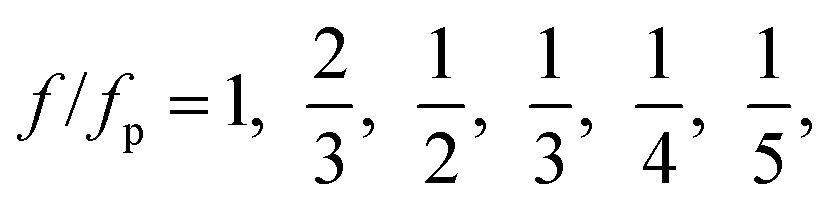
At a fixed set of flow rates without perturbation, the T-junction generates droplets steadily with a fundamental frequency, f = f0. The generation frequency, f, changed after introducing the system perturbation. The droplets could either be generated irregularly with high variation in droplet sizes (quasi-periodic regime), or regularly with f correlated with the perturbation frequency, fp (synchronized regime). In the synchronized regime, fp is near f0 or a multiple of f0. For instance, if the pressure amplitude ranges from 0.7 to 1.4 bar, with Qd = 18 and Qc = 240 μL h−1, the synchronized regime appears at a frequency ratio of:
 | (8) |
 | (9) |
By choosing a suitable pressure amplitude and plotting the susceptibility 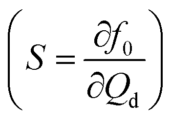 against f0/fp, an optimized flow rate Qd can be found within a wide range of fp producing f/fp = 1. Obtaining a wide range of generation frequencies f and droplet sizes at a fixed set of flow rates is important to achieve active control. For instance, with P = 1.7 bar and fixed flow rates of Qd = 6 and Qc = 240 μL h−1 the system can deliver a generation frequency f from 2 to 30 Hz and a corresponding droplet volume from 100 to 1000 pL. The advantage of this design is the small perturbation needed to influence the droplet generation frequency. However, the system needs to be fully characterized to determine the optimized flow rates and pressure amplitude for synchronized droplet generation. The applicable flow rates are limited as for most of the flow rates the perturbation induces the quasi-periodic regime that produces droplets with an irregular period and size.
Instead of incorporating vertically moving valves that require a multilayer fabrication process, Lee's group later used a pair of horizontally moving valves94 which were easier to fabricate. The design requires the fabrication of only one layer of PDMS as the actuation channels are now in the same plane as the droplet channel (Fig. 5(d)). The horizontally actuating valves deform the main channel, which chops the narrow stream and forms the droplets. The drawback of this design is the relatively low generation frequency of only up to 17.4 Hz.
Steady on demand generation of droplets (Steady Drop on Demand, SDOD) was performed by full control of the instantaneous flow rates, generally of the dispersed phase. Lin et al.95 activated the valve periodically while maintaining constant pressures on the dispersed and continuous phases. The resulting droplet volume (V) increases with increasing opening duration (T0):
| V = kT0a, | (10) |
SDOD provides extra degrees of freedom for the controllability of the droplet generation process. The approach is able to produce a selected droplet volume within a large range. Also, the timing of droplet generation is fully controllable.95 However, the frequency of droplet generation is limited by the time taken to open or close the valves. As a result, the frequency of droplet generation is limited to below 20 Hz. The system by Lin et al. requires a round profile to allow sufficient flow blockage when the valve is fully expanded. The channel cannot be fabricated using SU-8 resin unless it is post-processed using a photo-polymerization technique.101
Lee et al. proposed a predictive model for Drop on Demand (DOD) generation.102 The dispersed phase was introduced from the side channel and the continuous phase through the central one. Using the analogy to an electronic circuit, a fluidic circuit model was formulated. The flow rate of the dispensed phase (Qd) was determined by solving the equations with Kirchhoff's circuit laws. Finally, the theoretical droplet volume can be simply calculated as Vtheo = Qdt, where t is the activation time. Instead of the applied pressure at the inlet, Zeng et al.96 used negative pressure at the outlet for the DOD concept. The droplet size measured in the area increased linearly with T0 in the pressure range from −28.6 to −44.4 kPa. With the pressure as a single driving parameter, the system is easy to operate. Multiple T-junctions with individually controllable pneumatic valves allow for the generation of droplets from different sources (Fig. 5(f)).
Ochs et al. designed pincer microvalves that do not only allow DOD generation but also the control of the dispersed phase flow rate.103 Leung et al., on the other hand, embedded a series of microvalves that make up a programmable droplet-based microfluidic device for sample compartmentalization.104
The response of DOD can be further improved using devices made of a stiff material.97 However, integrated membrane valves can only be fabricated in devices made of elastomer such as PDMS. Galas et al. solved this problem by decoupling the device design from the flow controlling system.97 An active connector made of PDMS with an integrated membrane valve controls the flow of the dispersed phase (Fig. 5(g)). The rest of the device is made of a hard material (NOA81).
Churski et al. reported a similar approach using a stiff device and an external valve module.98,105 The module is modified from an off-the-shelf electromagnetic valve (EMV) to reduce the flow through the valve and lessen the build-up of pressure at the downstream.105 It can also be modified from an EMV using a slab of polycarbonate and a nitrile membrane.98 In order to further shorten the opening and closing time of the valve, a pair of EMVs is also used for each inlet (Fig. 5(h)).98 EMVhigh is connected to a compressed air source while EMVlow is connected to an atmospheric pressure or vacuum source. As a result, the minimum time T0 required for on demand generation is reduced to 25 ms, about half the time needed by a setup using one EMV only. In their later work, Churski et al. also provided practical guidelines for the use of low-cost EMVs to generate nanoliter droplets on demand (Table 5).34
| Source | Mechanism | Flow channel geometrya | Fluidsb | Notes |
|---|---|---|---|---|
| a H – height in μm; W – width in μm. b C – continuous phase; D – dispersed phase. | ||||
| Ref. 92 | Perturbation | T-junction: | C = tetradecane + 1–3% Span 80 | Perturbation frequency = 2–13 Hz |
| H = 20 or 40 | D = DI water + fluorescein | *Side W is not stated | ||
| Main W = 200 | ||||
| Ref. 93, 94 | Chopping | Flow focusing: | C = trioctanoin + polyglyceryl-2 sesquiisostearate + PEG-10 polyglyceryl-2 Laurate | Chopping frequency: <17 Hz |
| H = 100 | D = DI water + 0.1% Vitamin C | |||
| W = 60 | ||||
| Ref. 95 | Flow manipulation | T-junction: | C = Oleic acid/hexadecane/silicone oil + 5% Span 80 | Dispensing time >50 ms |
| H = 25 | D = DI water | |||
| Main & side W = 150 | ||||
| Ref. 102 | Flow manipulation | T-junction: | C = mineral oil | Dispensing time >40 ms |
| H = 11.5, 13.6, 15.3 | D = water + 10% pigment solution/sodium alginate solution (0.1% or 0.5%) | |||
| Main W = 90 | ||||
| Side W = 50 | ||||
| Ref. 96 | Flow manipulation | T-junction: | C = oleic acid + 2.5% Span 80 | Dispensing time >50 ms |
| H = 200 | D = water + diluted colored ink | |||
| Main W = 200 | ||||
| Side W = 240 | ||||
| Ref. 97 | Flow manipulation | T-junction: | C = mineral oil + 4.5% span 80 + 0.4% Tween 80 + 0.05% Triton X100 | Dispensing time >40 ms *Side W is not stated |
| H = 80, main W = 200 | D = water + red dye | |||
| Ref. 98 | Flow manipulation | T-junction: | C = hexadecane + 2% Span 80 | Dispensing time >25 ms |
| H = 200, main W = 400 | D = water | *Side W is not stated | ||
| Ref. 99, 106 | Geometry tuning | Flow focusing: | C = DI water + 5% Triton X-100 | Droplet formation frequency <24 Hz |
| H = 100 | D = olive oil | |||
| W = 100 | ||||
| Orifice W = 70 | ||||
| Ref. 32 | Geometry tuning | Flow focusing: | C = HFE-7500 fluorocarbon + 5% 1H,1H,2H,2H-perfluoro-1-octanol + 1.8% fluoro-surfactant ammonium carboxylate | Droplet formation frequency <3000 Hz |
| H = 50 | D = water | |||
| W = 20 | ||||
| Ref. 107 | Geometry tuning | T-junction: | C = squalene oil + DDAB + negative-charged DNA modules | Droplet formation frequency <4000 Hz |
| H = 100 | D = DI water + 2.5% Tween 20 | |||
| Main W = 150 | ||||
| Side W = 100 | ||||
| Ref. 100 | Geometry tuning | Flow focusing: | C = olive oil | Droplet formation frequency <96 Hz |
| H = 50 | D = DI water + 3% Triton X-100 | |||
| W = 85 | ||||
Abate et al. investigated the control of droplet formation further, using the same type of actuation.32 The valves are incorporated in the orifice downstream of a flow-focusing junction. The droplet size decreases and the generation frequency increases with decreasing orifice cross section:
 | (11) |
Statically actuated valves tuning the channel geometry allow the control over a wider range of generation frequencies than the dynamically actuated counterparts. Dynamically actuated valves allow the generation on demand of virtually any polydisperse distribution droplet size with a characteristic time as short as the valve response time. Statically actuated valves cover a wider range of overall frequencies for a fixed monodisperse size. A similar concept was applied to a T-junction device using a horizontally moving valve.107 The location of the valve is significant for the generation process. A valve located downstream of the junction easily reduces the droplet size. A valve placed upstream of the junction does not affect the droplet size.
Lee's group also used a statically actuated valve in the dispersed phase channel100 (Fig. 5(j)). The channel size is tuned by varying the negative actuation pressure. As the pressure in the actuation channel decreases, the channel cross section increases, reducing the velocity of the dispersed phase. However, the streamlines become more concentrated at the centerline when the fluid exits the restriction with a higher velocity. In the flow-focusing configuration, the dispersed phase stream appears to be finer and consequently produces smaller droplets. Compared to other tunable designs, this device generates small droplets without deforming the channel excessively.
5.2 Piezoelectricity control
Piezoelectricity is used for a variety of applications such as sound/ultrasound generation, mechanical actuation, sensing and signal processing.108 Piezoelectric actuation has also been used to control microfluidic droplet generation. The control approaches can be categorized according to the function of the piezoelectric element (Fig. 6). For dispensing purposes, a piezoelectric actuator can be used to supply a fixed amount of dispersed phase for on-demand droplet generation as in ink-jet printing applications. On the other hand, piezoelectric actuation can disturb the interface between continuous and dispersed phases and affect the droplet generation process.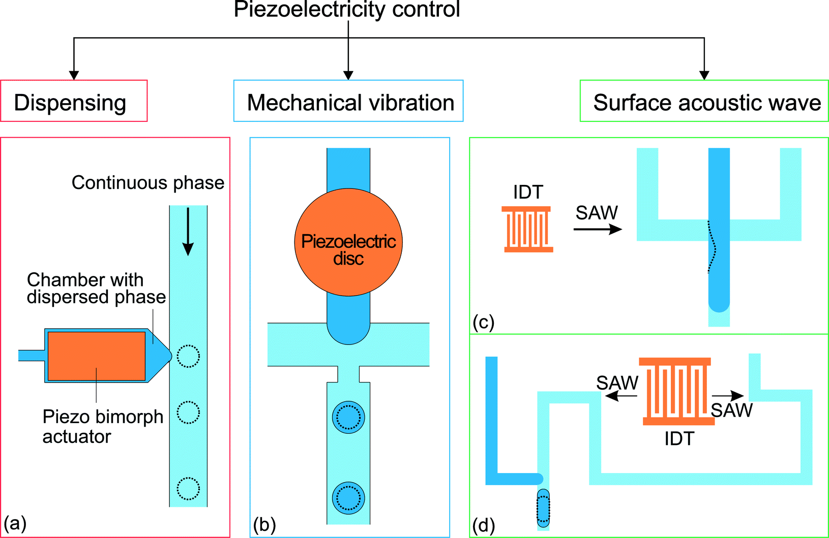 | ||
| Fig. 6 Classification of the approaches for piezoelectricity control. (a) T-junction integrated with a piezo bimorph actuator.109 (b) Flow focusing device with a piezoelectric disc to vibrate the oil–water interface formed during the droplet generation process.110,111 (c) Flow focusing device integrated with an interdigital transducer (IDT) to generate SAW.112 (d) T-junction integrated with an IDT without the SAW influencing the oil–water interface. The dotted lines illustrate the changes after activation of the piezoelectricity control.113 | ||
| Us = πd2γ, | (12) |
 | (13) |
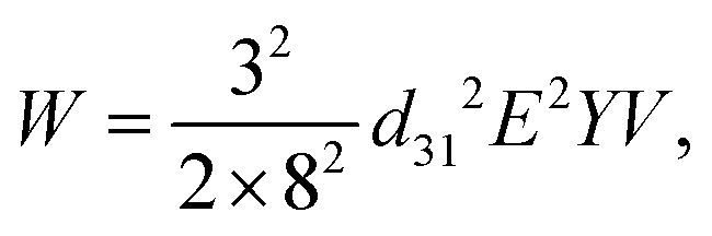
The droplet size is controlled by tuning the duration of the driving pulse and its voltage. Compared to the previously mentioned on-demand droplet generation approaches using pneumatic/hydraulic actuation, piezoelectric actuation is faster. While pneumatic/hydraulic actuation allows for 40 ms dispensing time, piezoelectric actuation can achieve 200 μs. The shorter dispensing time increases the generation frequency by more than two orders of magnitude. In addition to the simple one-by-one droplet dispensing mode, controlling the pulse patterns can generate droplets with different volumes. Dispensing a doublet or the generation of two droplets per pulse was demonstrated. This droplet dispensing approach involves large, rapid movement of the oil–water interface, which may lead to the formation of satellite droplets. Furthermore, the duration of the device is challenged as large chamber deformations are required to produce a droplet. Bransky et al. used piezoelectric dispensing of individual droplets in a flow focusing configuration.114 Compared to the T-junction configuration, the actuation chamber is smaller, as the flow-focusing configuration locally amplifies the pressure on the liquid interface. The smaller chamber also eliminates the generation of satellite droplets due to the smaller deformation at the oil–water interface. The location of the oil–water interface was adjusted by the height of each liquid.
Apart from attaching the piezoelectric actuator on the device for dispensing purposes, Shemesh et al. and Jakiela et al. also attached the actuator externally.115,116 The working principle is similar to the mechanism of flow manipulation using the electromagnetic valves (EMVs) discussed in the mechanical control section. Though, EMVs have much slower response compared to piezoelectric actuators (Table 6).116
| Source | Mechanism | Flow channel geometrya | Fluidsb | Notes |
|---|---|---|---|---|
| a H – height in μm; W – width in μm. b C – continuous phase; D – dispersed phase. | ||||
| Ref. 109 | Dispensing | T-junction: | C = hexadecane | Dispensing frequency <2.5 kHz |
| H = 50–100, Main W = 250 | D = water | |||
| Nozzle W = 25–100 | ||||
| Ref. 114 | Dispensing | T-junction: | C = oleic acid | Dispensing frequency <500 Hz |
| H = 50 | D = DI water | |||
Side W to channel W ratio =  and 1 and 1 |
||||
| Flow focusing: | ||||
| H = 50 | ||||
Orifice W to channel W ratio =  and 1 and 1 |
||||
| Ref. 110 | Mechanical vibration | Flow focusing: | C = mineral oil M5904 (light, 32 mPa s), paraffin oil 76235 (116 mPa s), mineral oil 330760 (heavy, 170 mPa s) D = DI water | Vibration frequency = 250–750 Hz |
| H = 100, main W = 150 | ||||
| Orifice W = 40 | ||||
| Ref. 111 | Mechanical vibration | Flow focusing: | C = mineral oil M5904 + 1.2% Span 80 | Vibration frequency = 200–500 Hz |
| H = 90, main W = 150 | D = DI water | |||
| Orifice W = 40 | ||||
| Ref. 117 | Mechanical vibration | Flow focusing: | C = 20% polyethyleneglycol (PEG) in water | Vibration frequency = 2–50 Hz |
| H = 85, W = 100 | D = 10% dextran in water | |||
| Ref. 118 | Surface acoustic wave | Flow focusing: | C = HFE-7500 fluorocarbon + 1.8% DuPont Krytox 157 | Actuation frequency = 161–171 MHz |
| H = 30, W = 30 | D = water + bromophenol blue | |||
| Ref. 113 | Surface acoustic wave | T-junction: | C = HFE-7500 fluorocarbon + 1.8% DuPont Krytox 157 | Actuation frequency = 160 MHz |
| H = 25, main & side W = 25 | D = water + bromophenol blue | |||
| 119 | Surface acoustic wave | T-junction: | C = olive oil (85 cP) | Actuation frequency = 48.4 & 95.4 MHz |
| H = 30, main W = 30 | D = water | |||
| Side W = 20 | ||||
Ziemecka et al. used a similar setup to perturb an originally stable capillary jet formed at the flow focusing junction.117 As the jet travels downstream, it breaks into droplets with sizes dictated by the imposed perturbation wavelength. Sometimes, the newly formed droplet may further break up into two daughter droplets as it moves downstream. Under a constant flow rate, the droplet size decreases with increasing vibration frequency fv:
| qd = fvNV, | (14) |
 | (15) |
Schmid et al. used SAW to control the droplet size generated by a flow focusing device under a constant set of flow rates.118 The PDMS device with the microchannels is bonded directly to a flat piezoelectric LiNbO3 substrate with the IDT (Fig. 6(c)). The microchannel was aligned so that the IDT is located on the left side of the junction. The generated SAW travels along the microchannel for the continuous phase. The effect of the SAW on the droplet generation process is obvious upon activating the IDT. The SAW causes an asymmetric excitation of the thinning neck during the break up process (Fig. 6(c)). Consequently, the time to breakup is shortened and reduces the droplet size. This phenomenon intensifies with increasing electric power. A stronger SAW shifts the neck and the droplet formation site further downstream with an even shorter break up time. A subsequent study on the control of droplet generation utilized SAW in a T-junction configuration.113 The IDT is placed far away from the droplet formation site to prevent the SAW from affect the oil–water interface (Fig. 6(d)). In this study, the fluids are driven by pressure.
The droplet length decreases with increasing SAW power. The authors hypothesized that the SAW promoted a pressure gradient in the continuous phase. This hypothesis was tested by comparing the pressure at the droplet formation site of the two cases: with and without SAW. The increase in pressure can be related to the volume force generated when SAW couples into the continuous phase.113 The results of SAW-controlled droplet generation are close to that caused by the pressure increase in the continuous phase.
SAW control is an attractive approach as it allows contactless manipulation. The IDT can be located outside of the channel, preventing the electrodes from being in contact with the fluids directly. Furthermore, the IDT allows a small footprint suitable for integration into a small microfluidic device. However, the fabrication of the IDT requires a piezoelectric substrate, whose wetting properties might not be compatible with those of the channel material. Furthermore, a high-performance piezoelectric substrate could be expensive.
Collins et al. integrated a set of focused interdigital transducers (FIDT) on a modified T-junction device to enable on-demand droplet generation using SAW.119 The curved gold electrodes were patterned with the focal point at the junction. The continuous phase was fed at a constant flow rate by a syringe pump, while the pressure of the dispersed phase was adjusted to form a static oil–water interface at the junction. A SAW pulse forced the dispersed phase into the main channel. On-demand droplet generation was thus controlled by manipulating the power and the duration of the SAW pulse.
6. Other control methods
6.1 Electrical control with electrorheological fluid
Electrorheological fluids (ERFs) are made of dielectric particles suspended in a carrier fluid.125 Rheological properties such as viscosity and shear rate change if the fluid is subjected to an electric field.126 Under an electric field, the suspended particles are polarized and aggregate along the field direction.125 This feature allows the viscosity of the fluid to be electrically controlled, reversibly and continuously, even from the liquid to the solid state. ERFs have already found applications in automotive devices such as engine dampers and vehicle shock absorbers.126 ERFs have been used in micropumps, microvalves and micromixers.121 Giant electrorheological fluids (GERFs), a recently developed kind of ERFs with much higher yield strength than the conventional ERFs, were also used in microfluidic devices.127Zhang et al. reported the use of GERFs for droplet generation in a microfluidic device.121 Four fluid contacting electrodes were patterned near the droplet formation junction (Fig. 7(a)). The electrodes were made of PDMS-based conducting composites loaded with black carbon nanoparticles. In that setup, the GERF was used as the continuous phase while water served as the dispersed phase. Before applying a voltage to the electrodes, long water plugs were formed stably at the junction. This process was interrupted by the application of a voltage on the electrodes, stopping the GERF flow. Only water flowed through the junction. If the voltage decreases to a critical value, the GERF rushes again into the junction, breaks the water stream and forms a new droplet. This process allows the generation of droplets to be controlled by the frequency. The same approach was used for a T-junction configuration with similar results. Niu et al. used GERF as the dispersed phase.122 The carrier fluid of the GERF is sunflower seed oil, which is immiscible with the silicone oil used as the continuous phase. The fabrication of this device is similar to their previous one but the design was changed to suit this approach (Fig. 7(b)), only 2 electrodes around the junction were used to control the dispersed phase (Table 7).
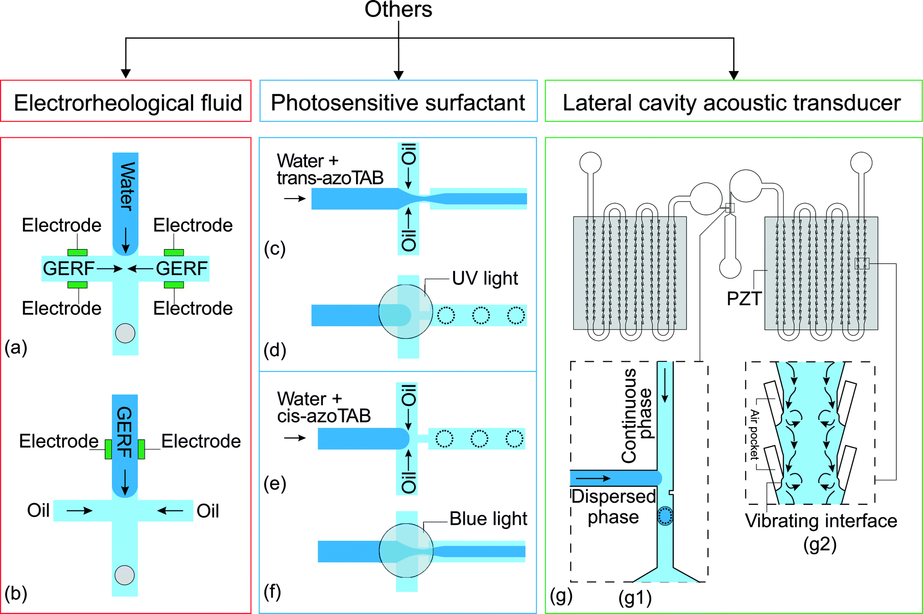 | ||
| Fig. 7 Flow focusing junction design with electrodes to control the flow rate of (a) the continuous phase121 and (b) the dispersed phase.122 (c and d) Flow focusing junction with trans-azoTAB photosensitive surfactant in the dispersed phase,123 (c) before and (d) after activation with UV light, and (e and f) with cis-azoTAB in the dispersed phase (e) before activation (f) after activation with blue light. (g) A T-junction droplet generation device integrated with two LCAT pumps:124 (g1) droplet generating T-junction with a constriction that facilitates the formation of droplet; (g2) magnified part of the LCATs with the streaming flow generated by the vibrating interface. The dotted lines illustrate the changes after activation of the control. | ||
| Source | Control method | Flow channel geometrya | Fluidsb | Notes |
|---|---|---|---|---|
| a H – height in μm; W – width in μm. b C – continuous phase; D – dispersed phase. | ||||
| Ref. 121 | Electrical control with electrorheological fluid | Flow focusing: | C = sunflower oil based GER fluid | Voltage < 1.5 kV |
| H = 100, W = 200 | D = water | Frequency < 250 Hz | ||
| Ref. 122 | Electrical control with electrorheological fluid | Flow focusing: | C = silicone oil (50 cSt) | Voltage < 1.5 kV |
| H = 100, W = 200 | D = sunflower oil based GER fluid | Frequency < 250 Hz | ||
| Ref. 128 | Electrical control with electrorheological fluid | Flow focusing: | C = silicone oil (100 cSt) | Voltage < 450 V |
| H = 90, W = 200 | D = sunflower oil based GER fluid | |||
| Ref. 129 | Photosensitive surfactant | Flow focusing with orifice: | C = oleic acid | UV illumination at λ = 365 nm* Channel H is not stated |
| Dispersed phase W = 90 | D = trans-AzoTAB (12.6 mM) or cis-AzoTAB (14.6 mM) in water | |||
| Continuous phase and downstream W = 100 | ||||
| Orifice W = 33 | ||||
| Ref. 130 | Lateral cavity acoustic transducer (LCAT) pump | T-junction: | W/O droplets | Acoustic frequency = 67.7 kHz |
| H = 100 | C = mineral oil (20 cp) + 2% span 80 | Applied voltage: | ||
| Main & side W = 100 | D = DI water | V oil = 4–9 Vpp | ||
| O/W droplets | V water = 2–6 Vpp | |||
| C = DI water + 2% Tween 20 | ||||
| D = mineral oil (20 cp) | ||||
Both control approaches using GERF are attractive as they provide a quick response time of less than 10 ms. The droplet size was determined by the applied frequencies and the shape of the control signal. This feature and control mechanism was adopted to perform 16 logic operations using KCl droplets as the signals.128 However, given that the fluids are flow-rate driven by syringe pumps, the flow rates of GERF and the other liquid should be carefully selected to prevent bursting of the channels or connections as the pressures build up in each fluid circuit. Another drawback is the concentration of the suspended dielectric particles in the GERF, which is over 20 wt% for effective control and might be too high for many applications.
6.2 Photosensitive surfactant
Photosensitive surfactants have been used to make droplet generation controllable by light. Diguet et al. introduced this control method using azobenzene trimethylammonium bromide surfactant (azoTAB).129 AzoTAB surfactant is available either in the trans or cis form under normal room light conditions. Trans(cis) form azoTAB converts to the cis(trans) form upon illumination of ultraviolet (UV) light.123 The conversion is reversible, as they restore to their original forms once UV light is removed. The concept was demonstrated in a flow focusing configuration, where the dispersed phase is water with trans-azoTAB surfactant and the continuous phase is oleic acid. Initially, the flow rates are set to maintain a thin aqueous stream co-flowing with the continuous stream in the center (Fig. 7(c)). After exposing the junction to UV light for about 2 s, the middle stream breaks and starts to generate monodisperse droplets (Fig. 7(d)). As cis-azoTAB decreases the surface tension of the dispersed stream, the stability of the capillary jet changes to the dripping regime.16,131 However, the transition does not happen at a high total flow rate, it is when the system is dominated by viscous forces.131Apart from the jetting/dripping transition, UV light was also used to modify the droplet size under normal room light conditions. As UV light is applied and surface tension increases, the droplet breaking site moves upstream, forming larger droplets. With cis-azoTAB (see Fig. 7), the dripping regime (e) turns into the jetting regime (f) after being exposed to blue light. This is consistent with the fact that the water stream with trans-azoTAB, which is converted by the blue light from cis-azoTAB, has a lower surface tension than the one with cis-azoTAB. Control with a photosensitive surfactant is easy to implement. The system does not require a high concentration of azoTAB to have a significant effect on control. However, the response to the control is slow as it takes seconds to reach a new stable state after the change in wettability by the respective light.
6.3 Lateral cavity acoustic transducer (LCAT) pump
The pressure rarefaction and compression induced by an acoustic pulse can expand and contract highly compressible bubbles.132 When bubbles are trapped in the liquid, the application of a periodic acoustic pulse vibrates the gas–liquid interface and forms a second-order streaming flow in the liquid around the interface.124,133 This phenomenon of acoustic streaming has been applied for pumping, mixing, sonoporation of suspended cells and sorting of microparticles.134One of the designs using this method is the Lateral Cavity Acoustic Transducer (LCAT), which was introduced by Lee's group in 2008 to pump and mix fluids.124 As shown in the inset of Fig. 7(g), a LCAT consists of an air pocket formed when fluid passes through the dead-end side channel. The LCAT was activated when a piezoelectric (PZT) disc attached at the bottom of the device is driven by an AC signal. The acoustic wave from PZT vibrates the interface of the air pocket and induces acoustic streaming. That flow provokes a net bulk flow downstream. Integrating multiple LCATs along a channel allows them to collectively work as a pump with a reasonably high driving pressure.135
LCAT pumps have been integrated into microfluidic droplet generating devices to drive fluids without using bulky instruments such as a syringe pump and pressure controllers.130 The device consists of two LCAT pumps (Fig. 7(g)). Each pump consisting of 96 pairs of LCATs was activated individually by a PZT to drive one liquid phase. As shown in the inset of Fig. 7(g), droplets are formed at a T-junction. Varying the voltage applied to the PZTs tunes the size of the droplets.
Control of droplet generation using LCAT pumps is attractive as they are small enough to be integrated into a microfluidic device. Compared to the conventional systems, the distance from the pumps to the droplet generating site is reduced significantly. As a result, the flow rates at the generating site can be changed much faster because of the smaller inertia of the system. However, in order to form air pockets of a desirable size and shape at the LCATs, the channel needs to be both hydrophobic and lipophobic. For this reason, the inner device surface is coated with perfluorodecyltrichlorosilane (FDTS), with a limited lifetime of a couple of days. Furthermore, the power of the LCAT pump is still limited, even with the optimized geometry. The maximum generation frequency of the device was 31 Hz, for water in oil droplets and 59.1 Hz for oil in water droplets.
7. Conclusions
Microfluidics is one of the enabling technologies in chemical engineering and biotechnology. Controlling the droplet generation process is one of the important and central topics of microfluidics. The control process is physically more complex than processes in other technologies such as microelectronics or photonics. Even with limited geometrical designs and configurations, the various parameters and scales present in the formation of a droplet are far beyond controllability (see for example ref. 136 and references therein). These local degrees of freedom become augmented when rheological properties, hysteretic effects, or issues from biological origin come into play. Further problems such as limited mechanical resistance, reproducibility, or throughput, often make early expectations fail when microfluidics technology is translated into practical products.With this review, we aim to provide a comprehensive and systematic overview of active control methods of droplet generation in microfluidics. We summarized the different ways for active control of droplet generation. These methods can be classified according to the energy type: (i) electrical, (ii) thermal, (iii) magnetic, (iv) mechanical, and even chemical. In some cases, the control concept involves more than one of those energies. The creativity exhibited by many authors has been admirable. However, reducing the size of the system is becoming the current fundamental challenge for active control.
References
- P. Gravesen, J. Branebjerg and O. S. Jensen, J. Micromech. Microeng., 1993, 3, 168 CrossRef CAS.
- D. J. Beebe, G. A. Mensing and G. M. Walker, Annu. Rev. Biomed. Eng., 2002, 4, 261–286 CrossRef CAS PubMed.
- G. M. Whitesides, Nature, 2006, 442, 368–373 CrossRef CAS PubMed.
- D. C. Duffy, J. C. McDonald, O. J. A. Schueller and G. M. Whitesides, Anal. Chem., 1998, 70, 4974–4984 CrossRef CAS PubMed.
- M. A. Unger, H. P. Chou, T. Thorsen, A. Scherer and S. R. Quake, Science, 2000, 288, 113–116 CrossRef CAS PubMed.
- F. H. A. T. Thorsen, R. W. Roberts and S. R. Quake, Phys. Rev. Lett., 2001, 86, 4163–4166 CrossRef PubMed.
- S. L. Anna, N. Bontoux and H. A. Stone, Appl. Phys. Lett., 2003, 82, 364–366 CrossRef CAS.
- D. B. Bogy, Annu. Rev. Fluid Mech., 1979, 11, 207–228 CrossRef.
- J. Eggers, Rev. Mod. Phys., 1997, 69, 865–929 CrossRef CAS.
- O. A. Basaran, AIChE J., 2002, 48, 1842–1848 CrossRef CAS.
- P. Garstecki, H. A. Stone and G. M. Whitesides, Phys. Rev. Lett., 2005, 94, 164501 CrossRef PubMed.
- P. Garstecki, M. J. Fuerstman, H. A. Stone and G. M. Whitesides, Lab Chip, 2006, 6, 437–446 RSC.
- A. Yarin, Annu. Rev. Fluid Mech., 2006, 38, 159–192 CrossRef.
- Ö. E. Yildirim and O. A. Basaran, J. Non-Newtonian Fluid Mech., 2006, 136, 17–37 CrossRef.
- J. Eggers and E. Villermaux, Rep. Prog. Phys., 2008, 71, 036601 CrossRef.
- M. A. Herrada, A. M. Gañán-Calvo and P. Guillot, Phys. Rev. E: Stat., Nonlinear, Soft Matter Phys., 2008, 78, 046312 CrossRef CAS PubMed.
- Z. Nie, M. Seo, S. Xu, P. Lewis, M. Mok, E. Kumacheva, G. Whitesides, P. Garstecki and H. Stone, Microfluid. Nanofluid., 2008, 5, 585–594 CrossRef CAS.
- M. A. Herrada, J. M. Montanero, C. Ferrera and A. M. Gañán-Calvo, J. Fluid Mech., 2010, 649, 523–536 CrossRef CAS.
- S. H. Tan, N.-T. Nguyen, L. Yobas and T. Kang, J. Micromech. Microeng., 2010, 20, 045004 CrossRef.
- A. M. Gañán-Calvo, Phys. Rev. Lett., 1998, 80, 285–288 CrossRef.
- P. Garstecki, I. Gitlin, W. DiLuzio, G. M. Whitesides, E. Kumacheva and H. A. Stone, Appl. Phys. Lett., 2004, 85, 2649–2651 CrossRef CAS.
- S. Takeuchi, P. Garstecki, D. B. Weibel and G. M. Whitesides, Adv. Mater., 2005, 17, 1067–1072 CrossRef CAS.
- A. M. Gañán-Calvo, R. González-Prieto, P. Riesco-Chueca, M. A. Herrada and M. Flores-Mosquera, Nat. Phys., 2007, 3, 737–742 CrossRef.
- M. A. Herrada, A. M. Gañán-Calvo, A. Ojeda-Monge, B. Bluth and P. Riesco-Chueca, Phys. Rev. E: Stat., Nonlinear, Soft Matter Phys., 2008, 78, 036323 CrossRef PubMed.
- S. H. Tan, B. Semin and J.-C. Baret, Lab. Chip, 2014, 14, 1099–1106 RSC.
- H. Yu, Z. Z. Chong, S. B. Tor, E. Liu and N. H. Loh, RSC Adv., 2015, 5, 8377–8388 RSC.
- M. A. Herrada and A. M. Gañán-Calvo, Phys. Fluids, 2009, 21, 042003 CrossRef.
- A. S. Utada, E. Lorenceau, D. R. Link, P. D. Kaplan, H. A. Stone and D. A. Weitz, Science, 2005, 308, 537–541 CrossRef CAS PubMed.
- A. M. Gañán-Calvo and J. M. Gordillo, Phys. Rev. Lett., 2001, 87, 274501 CrossRef PubMed.
- A. Gañán-Calvo, U.S. Pat., US 6,116,516, 1998 Search PubMed.
- T. Ward, M. Faivre, M. Abkarian and H. A. Stone, Electrophoresis, 2005, 26, 3716–3724 CrossRef CAS PubMed.
- A. R. Abate, M. B. Romanowsky, J. J. Agresti and D. A. Weitz, Appl. Phys. Lett., 2009, 94, 023503 CrossRef.
- H. A. Stone, A. D. Stroock and A. Ajdari, Annu. Rev. Fluid Mech., 2004, 36, 381–411 CrossRef.
- K. Churski, M. Nowacki, P. M. Korczyk and P. Garstecki, Lab Chip, 2013, 13, 3689 RSC.
- R. Seemann, M. Brinkmann and T. P. S. Herminghaus, Rep. Prog. Phys., 2012, 75, 016601 CrossRef PubMed.
- G. F. Christopher and S. L. Anna, J. Phys. D: Appl. Phys., 2007, 40, R319–R336 CrossRef CAS.
- S.-Y. Teh, R. Lin, L.-H. Hung and A. P. Lee, Lab Chip, 2008, 8, 198–220 RSC.
- C. N. Baroud, F. Gallaire and R. Dangla, Lab Chip, 2010, 10, 2032–2045 RSC.
- A. B. Theberge, F. Courtois, Y. Schaerli, M. Fischlechner, C. Abell, F. Hollfelder and W. T. S. Huck, Angew. Chem., Int. Ed., 2010, 34, 5846–5868 CrossRef PubMed.
- J.-S. Chen and J.-H. Jiang, Chin. J. Anal. Chem., 2012, 40, 1293–1300 CrossRef CAS.
- K.-Y. Song and W.-J. Zhang, Recent Pat. Nanotechnol., 2013, 7, 133–152 CrossRef CAS PubMed.
- C. X. Zhao, Adv. Drug Deliv. Rev., 2013, 65, 1420–1446 CrossRef CAS PubMed.
- N.-T. Nguyen and S. H. Tan, in Microdroplet Technology, ed. P. Day, A. Manz and Y. Zhang, Springer New York, 2012, pp. 51–75 Search PubMed.
- D. R. Link, E. Grasland-Mongrain, A. Duri, F. Sarrazin, Z. Cheng, G. Cristobal, M. Marquez and D. A. Weitz, Angew. Chem., Int. Ed., 2006, 45, 2556–2560 CrossRef CAS PubMed.
- H. Kim, D. Luo, D. Link, D. A. Weitz, M. Marquez and Z. Cheng, Appl. Phys. Lett., 2007, 91, 133106 CrossRef.
- F. Malloggi, S. A. Vanapalli, H. Gu, D. van den Ende and F. Mugele, J. Phys.: Condens. Matter, 2007, 19, 462101 CrossRef.
- H. Gu, M. H. G. Duits and F. Mugele, Lab Chip, 2010, 10, 1550 RSC.
- E. Castro-Hernández, P. García-Sánchez, S. H. Tan, A. M. Gañán-Calvo, J.-C. Baret and A. Ramos, Microfluid. Nanofluid., 2015, 1–8 Search PubMed.
- C. Ganan and S. Lopez-Herrera, Dispositif pour la production de jets capillaires et de particules micrometriques et nanometriques, WO Patent App. PCT/ES2003/000,065, 2003 Search PubMed.
- A. M. Gañán-Calvo, J. M. López-Herrera and P. Riesco-Chueca, J. Fluid Mech., 2006, 566, 421–445 CrossRef.
- J. Rodríguez-Rodríguez, A. Sevilla, C. Martínez-Bazán and J. M. Gordillo, Annu. Rev. Fluid Mech., 2015, 47, 405–429 CrossRef.
- A. M. Gañán-Calvo, Phys. Rev. Lett., 2007, 98, 134503 CrossRef PubMed.
- S. H. Tan, N.-T. Nguyen, Y. C. Chua and T. G. Kang, Biomicrofluidics, 2010, 4, 032204 CrossRef PubMed.
- D. A. Saville, Annu. Rev. Fluid Mech., 1997, 29, 27–64 CrossRef.
- A. M. Gañán-Calvo, N. Rebollo-Muñoz and J. M. Montanero, New J. Phys., 2013, 15, 033035 CrossRef.
- E. Cummings and B. Khusid, in Microfluidic Technologies for Miniaturized Analysis Systems, Springer US, 2007, pp. 315–355 Search PubMed.
- R. Cody, in Applied Electrospray Mass Spectrometry, CRC Press, 2002 Search PubMed.
- P. He, H. Kim, D. Luo, M. Marquez and Z. Cheng, Appl. Phys. Lett., 2010, 96, 174103 CrossRef.
- F. Mugele and J.-C. Baret, J. Phys.: Condens. Matter, 2005, 17, R705–R774 CrossRef CAS.
- C. Quilliet and B. Berge, Curr. Opin. Colloid Interface Sci., 2001, 6, 34–39 CrossRef CAS.
- F. Li and F. Mugele, Appl. Phys. Lett., 2008, 92, 244108 CrossRef.
- F. Malloggi, H. Gu, A. G. Banpurkar, S. A. Vanapalli and F. Mugele, Eur. Phys. J. E, 2008, 26, 91–96 CrossRef CAS PubMed.
- H. Gu, C. U. Murade, M. H. G. Duits and F. Mugele, Biomicrofluidics, 2011, 5, 011101 Search PubMed.
- H. Gu, F. Malloggi, S. A. Vanapalli and F. Mugele, Appl. Phys. Lett., 2008, 93, 183507 CrossRef.
- S. L. Anna and H. C. Mayer, Phys. Fluids, 2006, 18, 121512 CrossRef.
- T. B. Jones, K.-L. Wang and D.-J. Yao, Langmuir, 2004, 20, 2813–2818 CrossRef CAS PubMed.
- A. C. Siegel, S. S. Shevkoplyas, D. B. Weibel, D. A. Bruzewicz, A. W. Martinez and G. M. Whitesides, Angew. Chem., Int. Ed., 2006, 45, 6877–6882 CrossRef CAS PubMed.
- S. H. Tan, F. Maes, B. Semin, J. Vrignon and J.-C. Baret, Sci. Rep., 2014, 4, 4787 Search PubMed.
- N.-T. Nguyen, T.-H. Ting, Y.-F. Yap, T.-N. Wong, J. C.-K. Chai, W.-L. Ong, J. Zhou, S. H. Tan and L. Yobas, Appl. Phys. Lett., 2007, 91, 084102 CrossRef.
- C. A. Stan, S. K. Y. Tang and G. M. Whitesides, Anal. Chem., 2009, 81, 2399–2402 CrossRef CAS PubMed.
- C. N. Baroud, J.-P. Delville, F. M. C. Gallaire and R. Wunenburger, Phys. Rev. E: Stat., Nonlinear, Soft Matter Phys., 2007, 75, 046302 CrossRef PubMed.
- S.-Y. Park, T.-H. Wu, Y. Chen, M. A. Teitell and P.-Y. Chiou, Lab Chip, 2011, 11, 1010 RSC.
- Y.-F. Yap, S. H. Tan, N.-T. Nguyen, S. M. S. Murshed, T.-N. Wong and L. Yobas, J. Phys. D: Appl. Phys., 2009, 42, 065503 CrossRef.
- S. M. S. Murshed, S. H. Tan and N.-T. Nguyen, J. Phys. D: Appl. Phys., 2008, 41, 085502 CrossRef.
- S. M. S. Murshed, S. H. Tan, N. T. Nguyen, T. N. Wong and L. Yobas, Microfluid. Nanofluid., 2008, 6, 253–259 CrossRef.
- S. H. Tan, S. M. S. Murshed, N.-T. Nguyen, T. N. Wong and L. Yobas, J. Phys. D: Appl. Phys., 2008, 41, 165501 CrossRef.
- C. N. Baroud, M. R. de Saint Vincent and J.-P. Delville, Lab Chip, 2007, 7, 1029 RSC.
- J. Liu, S. H. Tan, Y. F. Yap, M. Y. Ng and N.-T. Nguyen, Microfluid. Nanofluid., 2011, 11, 177–187 CrossRef.
- J. Liu, Y. F. Yap and N.-T. Nguyen, Phys. Fluids, 2011, 23, 072008 CrossRef.
- Y. Wu, T. Fu, Y. Ma and H. Z. Li, Soft Matter, 2013, 9, 9792 RSC.
- C.-P. Lee, T.-S. Lan and M.-F. Lai, J. Appl. Phys., 2014, 115, 17B527 CrossRef.
- N. Pamme, Lab. Chip, 2006, 6, 24–38 RSC.
- Z. Z. Chong, W. J. Sim, Z. T. Yeo, K. H. Li, S. H. Ng, H. Xia, T. N. Wong, N. H. Loh, S. B. Tor, S. H. Tan and N.-T. Nguyen, Micro Nanosyst., 2014, 6, 232–236 CAS.
- K. Zhang, Q. Liang, X. Ai, P. Hu, Y. Wang and G. Luo, Lab Chip, 2011, 11, 1271 RSC.
- C.-H. Chen, A. R. Abate, D. Lee, E. M. Terentjev and D. A. Weitz, Adv. Mater., 2009, 21, 3201–3204 CrossRef CAS.
- Y. Wu, T. Fu, Y. Ma and H. Z. Li, Microfluid. Nanofluid., 2014, 18, 19–27 CrossRef.
- E. Surenjav, C. Priest, S. Herminghaus and R. Seemann, Lab Chip, 2009, 9, 325–330 RSC.
- C. P. Lee, H. Y. Tsai and M. F. Lai, Soft Matter, 2012, 8, 11537 RSC.
- N.-T. Nguyen, Microfluid. Nanofluid., 2011, 12, 1–16 CrossRef.
- É. du Trémolet de Lacheisserie, D. Gignoux and M. Schlenker, in Magnetism, Springer US, 2002, pp. 213–234 Search PubMed.
- S. H. Tan and N.-T. Nguyen, Phys. Rev. E: Stat., Nonlinear, Soft Matter Phys., 2011, 84, 036317 CrossRef PubMed.
- H. Willaime, V. Barbier, L. Kloul, S. Maine and P. Tabeling, Phys. Rev. Lett., 2006, 96, 054501 CrossRef CAS PubMed.
- C.-T. Chen and G.-B. Lee, J. Microelectromech. Syst., 2006, 15, 1492–1498 CrossRef.
- S.-K. Hsiung, C.-T. Chen and G.-B. Lee, J. Micromech. Microeng., 2006, 16, 2403–2410 CrossRef.
- B.-C. Lin and Y.-C. Su, J. Micromech. Microeng., 2008, 18, 115005 CrossRef.
- S. Zeng, B. Li, X. Su, J. Qin and B. Lin, Lab Chip, 2009, 9, 1340 RSC.
- J.-C. Galas, D. Bartolo and V. Studer, New J. Phys., 2009, 11, 075027 CrossRef.
- K. Churski, J. Michalski and P. Garstecki, Lab. Chip, 2010, 10, 512–518 RSC.
- C.-Y. Lee, Y.-H. Lin and G.-B. Lee, Microfluid. Nanofluid., 2008, 6, 599–610 CrossRef.
- J.-H. Wang and G.-B. Lee, Micromachines, 2013, 4, 306–320 CrossRef.
- W. Park, S. Han and S. Kwon, Lab Chip, 2010, 10, 2814 RSC.
- W. S. Lee, S. Jambovane, D. Kim and J. W. Hong, Microfluid. Nanofluid., 2009, 7, 431–438 CrossRef CAS.
- C. J. Ochs and A. R. Abate, Lab Chip, 2015, 15, 52–56 RSC.
- K. Leung, H. Zahn, T. Leaver, K. M. Konwar, N. W. Hanson, A. P. Page, C.-C. Lo, P. S. Chain, S. J. Hallam and C. L. Hansen, Proc. Natl. Acad. Sci. U. S. A., 2012, 109, 7665–7670 CrossRef CAS PubMed.
- K. Churski, P. Korczyk and P. Garstecki, Lab Chip, 2010, 10, 816 RSC.
- C.-H. Lee, S.-K. Hsiung and G.-B. Lee, J. Micromech. Microeng., 2007, 17, 1121–1129 CrossRef CAS.
- H.-W. Wu, Y.-C. Huang, C.-L. Wu and G.-B. Lee, Microfluid. Nanofluid., 2008, 7, 45–56 CrossRef.
- W. Heywang, Piezoelectricity evolution and future of a technology, Springer, Berlin, 2008 Search PubMed.
- J. Xu and D. Attinger, J. Micromech. Microeng., 2008, 18, 065020 CrossRef.
- Y. N. Cheung and H. Qiu, Phys. Rev. E: Stat., Nonlinear, Soft Matter Phys., 2011, 84, 066310 CrossRef PubMed.
- Y. N. Cheung and H. Qiu, J. Micromech. Microeng., 2012, 22, 125003 CrossRef.
- T. Franke, A. R. Abate, D. A. Weitz and A. Wixforth, Lab Chip, 2009, 9, 2625 RSC.
- L. Schmid and T. Franke, Appl. Phys. Lett., 2014, 104, 133501 CrossRef.
- A. Bransky, N. Korin, M. Khoury and S. Levenberg, Lab. Chip, 2009, 9, 516–520 RSC.
- J. Shemesh, A. Nir, A. Bransky and S. Levenberg, Lab Chip, 2011, 11, 3225 RSC.
- S. Jakiela, P. Debski, B. Dabrowski and P. Garstecki, Micromachines, 2014, 5, 1002–1011 CrossRef.
- I. Ziemecka, V. van Steijn, G. J. M. Koper, M. Rosso, A. M. Brizard, J. H. van Esch and M. T. Kreutzer, Lab. Chip, 2011, 11, 620–624 RSC.
- L. Schmid and T. Franke, Lab Chip, 2013, 13, 1691–1694 RSC.
- D. J. Collins, T. Alan, K. Helmerson and A. Neild, Lab Chip, 2013, 13, 3225–3231 RSC.
- X. Ding, P. Li, S.-C. S. Lin, Z. S. Stratton, N. Nama, F. Guo, D. Slotcavage, X. Mao, J. Shi, F. Costanzo and T. J. Huang, Lab Chip, 2013, 13, 3626 RSC.
- M. Zhang, J. Wu, X. Niu, W. Wen and P. Sheng, Phys. Rev. E: Stat., Nonlinear, Soft Matter Phys., 2008, 78, 066305 CrossRef PubMed.
- X. Niu, M. Zhang, J. Wu, W. Wen and P. Sheng, Soft Matter, 2009, 5, 576–581 RSC.
- C. T. Lee, K. A. Smith and T. A. Hatton, Macromolecules, 2004, 37, 5397–5405 CrossRef CAS.
- A. R. Tovar and A. P. Lee, Lab Chip, 2009, 9, 41–43 RSC.
- M. Zhang, X. Gong and W. Wen, Electrophoresis, 2009, 30, 3116–3123 CrossRef CAS PubMed.
- T. Hao, Electrorheological fluids the non-aqueous suspensions, Elsevier, Amsterdam Boston, 2005 Search PubMed.
- W. Wen, X. Huang, S. Yang, K. Lu and P. Sheng, Nat. Mater., 2003, 2, 727–730 CrossRef CAS PubMed.
- M. Zhang, L. Wang, X. Wang, J. Wu, J. Li, X. Gong, J. Qin, W. Li and W. Wen, Soft Matter, 2011, 7, 7493 RSC.
- A. Diguet, H. Li, N. Queyriaux, Y. Chen and D. Baigl, Lab Chip, 2011, 11, 2666 RSC.
- W.-F. Fang and A. P. Lee, Microfluid. Nanofluid., 2015, 18, 1265–1275 CrossRef CAS.
- A. M. Gañán-Calvo, Phys. Rev. E: Stat., Nonlinear, Soft Matter Phys., 2008, 78, 026304 CrossRef PubMed.
- K. Ferrara, R. Pollard and M. Borden, Annu. Rev. Biomed. Eng., 2007, 9, 415–447 CrossRef CAS PubMed.
- Z. Z. Chong, S. B. Tor, N. H. Loh, T. N. Wong, A. M. Gañán-Calvo, S. H. Tan and N.-T. Nguyen, Lab Chip, 2015, 15, 996–999 RSC.
- A. Hashmi, G. Yu, M. Reilly-Collette, G. Heiman and J. Xu, Lab Chip, 2012, 12, 4216–4227 RSC.
- A. R. Tovar, M. V. Patel and A. P. Lee, Microfluid. Nanofluid., 2011, 10, 1269–1278 CrossRef CAS.
- J. R. Castrejón-Pita, A. A. Castrejón-Pita, S. S. Thete, K. Sambath, I. M. Hutchings, J. Hinch, J. R. Lister and O. A. Basaran, Proc. Natl. Acad. Sci. U. S. A., 2015, 112, 4582–4587 CrossRef PubMed.
| This journal is © The Royal Society of Chemistry 2016 |