
 Open Access Article
 This Open Access Article is licensed under a
 Creative Commons Attribution 3.0 Unported Licence
An in vitro–in silico interface platform for spatiotemporal analysis of pattern formation in collective epithelial cells†
M.
Hagiwara
Nanoscience and Nanotechnology Research Center, Research Organization for the 21st Century, Osaka Prefecture University, Osaka, 599-8570, Japan. E-mail: m-hagiwara@21c.osakafu-u.ac.jp
First published on 19th July 2016
Abstract
A multicellular organization is a complex resulting from the coordinated migration of cells to form a specific pattern. The directionality of migration is governed by the mechanical and molecular dynamics of factors secreted from the cells. The mechanism underlying pattern formation is too complex to unveil by culture experiments alone. A mathematical model could provide a powerful tool for elucidating the mechanism of pattern formation by computing the molecular dynamics, which are difficult to visualize by culture experiments. However, there tends to be a gap between mathematical models and experimental research due to incongruity between the idealized conditions of the model and the experimental results. This paper presents an in vitro–in silico interface platform for elucidating the logic of multicellular pattern formation. Two-dimensional collective cell pattern formation was developed using normal human bronchial epithelial cells. Then, geometrical control of collective cells followed by feedback iteration was used to bridge the gap between the mathematical model and in vitro experiments. The mechanisms underlying the pattern formation of bronchial epithelial cells were evaluated using a reaction-diffusion model. The results indicated that differences in the diffusion rates of the activator and inhibitor determine the direction of collective cell migration to form a specific pattern.
Insight, innovation, integrationSpatiotemporal analysis of morphogens was performed to uncover the logic of pattern formation by collective cells of the bronchial epithelia. An in vitro–in silico interface platform to elucidate the logic of the system underlying multicellular pattern formation by bridging the gap between biological experiments and mathematical theory has been introduced. Controlling the initial culture conditions in vitro can reduce experimental noise to improve the reproducibility of developed pattern formation. This approach can allow the in vitro conditions to mimic the idealized conditions in silico and enhances the agreement of computational simulations with in vitro experiments. The mechanisms that determine the directionality of collective cell migration were revealed based on a reaction-diffusion (RD) model starting from various collective cell geometries. |
Introduction
Cells form a specific pattern by themselves in order to function as a tissue. Pattern formation in vivo involves a sophisticated process coordinated by a number of communications via a range of secreted molecular factors, yet the pattern developed is always the same, with little variation.1–3 Collective cell migration largely contributes to pattern formation,4–8 but the mechanisms involved in the development of multicellular organization are still poorly understood due to the complexity of the underlying system. It is not known how cells sense their position within the tissue structure or determine the direction of development. Understanding these mechanisms is crucial for pathological study and the development of regenerative medicine. Lung branching is one of the most complex tissue patterns.9 Research during the past few decades has helped to identify some of the key morphogens involved in forming the branching structure,10–13 but the logic of pattern formation is still not clear. In fact, various mathematical models have been proposed to simulate the branching formation;14 some models are based on mechanical interactions among epithelial cell sheets,15,16 while others are based on chemical reactions.17–19 One major reason for the enduring lack of clarity regarding the mechanisms of pattern formation is that there have been few successful in vitro experimental models. Unlike in vivo experiments, in vitro experiments can use a limited number of cell types to focus on individual physiological processes,20,21 but the considerable experimental noise due to procedural variation during operation obscures the underlying system. It is impossible to decode the mechanisms of pattern formation using experimental systems in which the pattern developed varies from one experiment to the next.Here, an in vitro two-dimensional (2D) experimental model of pattern formation in bronchial epithelial cells was developed. In 2D culture, the initial culture conditions can be controlled by microfabrication, and directional collective cell movements were generated under specific conditions. Using the developed in vitro experimental model, an in vitro–in silico interface platform was introduced to bridge the gap between biological experiments and mathematical theory (Fig. 1). Controlling the initial culture conditions in vitro can reduce the experimental noise to improve the reproducibility of the developed pattern formation. Then the remaining inherent experimental errors such as cell viability variations can be compensated by repetitive experiments. Multiple initial conditions are examined to avoid accidental matching of in vitro results and in silico results in order to validate the mathematical model itself as well as the model parameter. This approach can allow the in vitro conditions to mimic the idealized conditions in silico and enhances the agreement of computational simulations with in vitro experiments. Spatiotemporal analysis of morphogens was performed to uncover the logic of pattern formation by collective cells of the bronchial epithelia. The mechanisms that determine the directionality of collective cell migration were revealed based on a reaction-diffusion (RD) model starting from various collective cell geometries.
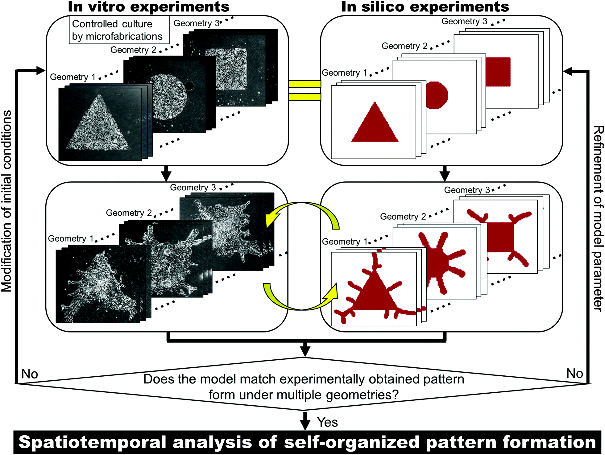 | ||
| Fig. 1 In vitro–in silico interface platform for elucidating the mechanisms underlying self-organized pattern formation. The initial cell conditions in vitro are controlled by the microfabrication technique to move closer toward the idealized conditions of mathematical models. Repetitive feedback cycles are conducted to refine model parameters. If the model can describe the pattern formation in vitro with multiple initial conditions with fixed parameters, spatiotemporal analysis can be conducted to uncover the system underlying the pattern formation. | ||
Materials and methods
Cell preparation
Normal human bronchial epithelial cells (NHBEs) were obtained from LONZA (Walkersville, MD) and cultured using the BEGM™ Bullet Kit (LONZA) supplemented with 50 IU ml−1 penicillin and 50 μg ml−1 streptomycin (Thermo Fisher Scientific Inc., MA). NHBEs were only used up to passage 7 in order to reduce the amount of variation in the developed patterns.Initial cell culture control
To develop branched pattern formation of NHBEs, Matrigel growth factor reduced (Corning Inc., Corning, NY) was used to coat cells with a high cell concentration gradient. The Matrigel formed a hydrogel after 25 minutes of incubation and then BEGM medium was added.Photolithography was employed to control the initial collective cell geometry and concentration (Fig. S1(a), ESI†). Before the fabrication process, a silicon substrate was soaked with a mixture of hydrogen peroxide and sulfuric acid (1![[thin space (1/6-em)]](https://www.rsc.org/images/entities/char_2009.gif) :2, v/v) for 10 min to clean the substrate, which was followed by rinsing with deionized water for 5 min twice. Then, the substrate was dehydrated in an oven at 140 °C for 20 min. A negative photoresist coating (SU-8 2100; MicroChem Corp., MA) was spin-coated onto the silicon substrate with approximately 150 μm thickness. Ultraviolet light irradiation was then conducted over a photomask with the desired geometric pattern, followed by a developing process involving 2-methoxy-1-methylethyl acetate. Once the photomask pattern was transferred to the photoresist coating, the silicon substrate was used as a mold for producing a poly-dimethylsiloxane (PDMS) membrane incised with the pattern. PDMS was poured onto the mold at a lower thickness than the SU-8 2100 layer and incubated in an oven for 20 min at 90 °C after degassing for 10 min. After the PDMS membrane was cured, it was detached from the silicon mold (Fig. S1(b), ESI†) and 70% (v/v) ethanol was sprayed on the membrane and plastic dish. The membrane was set on a plastic dish before the ethanol dried. Once the ethanol was evaporated in an oven at 80 °C for 10 min, the adhesion of the PDMS membrane to the dish was increased such that leakage was prevented during the subsequent step. Cell suspension medium was then applied over the membrane, and the dish was incubated at 37 °C until the cells reached the desired concentration in the unmasked area. The PDMS membrane was then removed and the cells were coated with Matrigel so that they could develop 2D branches on a plastic dish (Fig. S1(c), ESI†).
:2, v/v) for 10 min to clean the substrate, which was followed by rinsing with deionized water for 5 min twice. Then, the substrate was dehydrated in an oven at 140 °C for 20 min. A negative photoresist coating (SU-8 2100; MicroChem Corp., MA) was spin-coated onto the silicon substrate with approximately 150 μm thickness. Ultraviolet light irradiation was then conducted over a photomask with the desired geometric pattern, followed by a developing process involving 2-methoxy-1-methylethyl acetate. Once the photomask pattern was transferred to the photoresist coating, the silicon substrate was used as a mold for producing a poly-dimethylsiloxane (PDMS) membrane incised with the pattern. PDMS was poured onto the mold at a lower thickness than the SU-8 2100 layer and incubated in an oven for 20 min at 90 °C after degassing for 10 min. After the PDMS membrane was cured, it was detached from the silicon mold (Fig. S1(b), ESI†) and 70% (v/v) ethanol was sprayed on the membrane and plastic dish. The membrane was set on a plastic dish before the ethanol dried. Once the ethanol was evaporated in an oven at 80 °C for 10 min, the adhesion of the PDMS membrane to the dish was increased such that leakage was prevented during the subsequent step. Cell suspension medium was then applied over the membrane, and the dish was incubated at 37 °C until the cells reached the desired concentration in the unmasked area. The PDMS membrane was then removed and the cells were coated with Matrigel so that they could develop 2D branches on a plastic dish (Fig. S1(c), ESI†).
Reaction-diffusion model
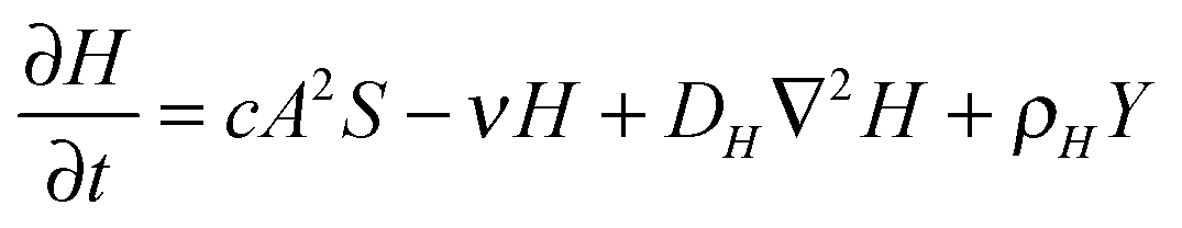
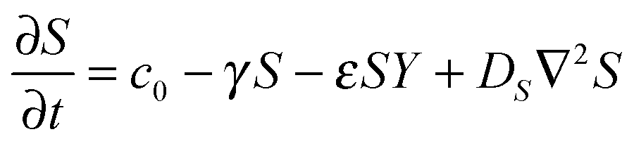
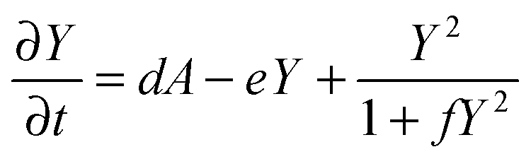
The RD model, which was initially proposed by A. Turning22 in the 1950s, mathematically expresses how morphogens spatially diffuse or react with other morphogens in order to generate specific patterns by computing large-scale signal communications. Two substances, an activator and an inhibitor, were considered to form a specific pattern. Subsequently, H. Meinhardt extended the RD model to incorporate elements such as the global network and branching as follows:23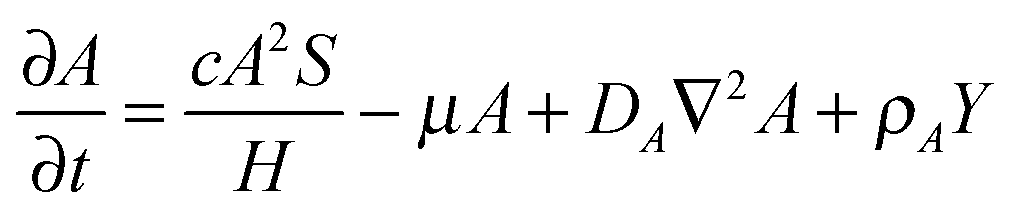 | (1) |
 | (2) |
 | (3) |
 | (4) |
Parameter refinements were conducted so that the pattern similarity between the in vitro experimental results and the RD model simulation results increased. The calculation methods of pattern similarity are described in the following section. Each parameter differently contributes to the pattern shape; for example, ρA and ρH are change the spatial interval of branches, and ε has correlation with the branch mode.19 All parameters are dimensionless, and after a number of refinements, the final parameters were set as follows: c = 0.04 ± 7%, μ = 0.1315, ν = 0.04, ρA = 0.01, ρH = 0.00015, c0 = 0.02, γ = 0.02, ε = 0.08, d = 0.013, e = 0.1, f = 10, DA = 0.02, DH = 0.18, DS = 0.12.
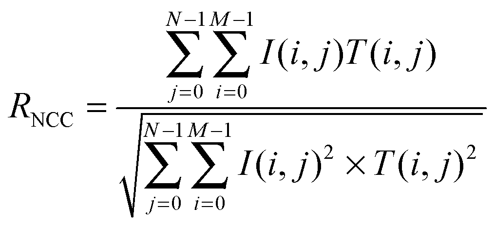
Calculation of branching pattern similarity
Normalized cross-correlation (NCC) was calculated after image processing to quantify the degree of similarity in the developed branching pattern formation. To determine the pattern, image processing was conducted using ImageJ (Fig. S2(a–f), ESI†). First, the edges of individual cells in the phase contrast image were detected by finding the maximum colour gradient points using the “Find edges” function in ImageJ. Then, the image was changed to a binary image (“Make binary”). The edge line was dilated followed by erosion (“Close”) and the small holes were filled (“Fill holes”) to identify the pattern area. Finally, the erosion operation was conducted again, followed by dilation (“Open”) to reduce signal noise.The similarity defined by NCC (RNCC) was then calculated between the template with M × N pixel size and the target image as follows:
Results
In vitro experiments of 2D pattern formation in bronchial epithelial cells
In our previous study, we succeeded in developing a hollow branching structure in vitro that is commonly observed in the lung airway, using only NHBEs.24 However, it is difficult to precisely repeat the same experimental conditions in three-dimensional (3D) culture due to operational variation and this variation is amplified with cell growth. These uncontrollable conditions give rise to a large amount of experimental noise and obscure the logic underlying the system. In addition, it was difficult to observe the patterns of branches widely spreading three-dimensionally. On the other hand, the current study found that collective cells formed specific patterns in 2D when NHBEs were set on a dish with a high cell concentration gradient covered by the extracellular matrix (ECM) (Fig. 2(a) and Video 1, ESI†). At the beginning, cells collectively migrated in a dynamic manner to form a finger-shaped structure similar to that formed by epithelial Madin–Darby canine kidney (MDCK) cells under specific conditions. Then the pattern of collective NHBEs bifurcated after the finger reached a certain length to form a “branch” structure. Unlike MDCK cells, the collective NHBEs continuously migrated without any leader cell.25,26 In contrast, cells grew without direction (Fig. 2(b)) when there was no ECM or when cells were homogeneously distributed (Fig. 2(c)).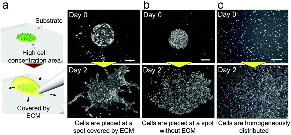 | ||
| Fig. 2 2D experimental model to generate pattern formation in bronchial epithelial cells. (a) When cells were placed with a high concentration gradient and were covered by the ECM, they showed 2D branching morphogenesis. (b) When cells were placed at a high concentration without any ECM, they proliferated and migrated without direction. (c) When cells were homogeneously distributed with the ECM, they barely migrated. Scale bars, 500 μm. (Video ESI†). | ||
Unlike 3D culture, the initial culture conditions can be controlled with relative ease for 2D culture, and observation of the developed pattern can be achieved using a standard microscope. Besides, the system does not require heterotypic cell–cell interactions; epithelial cells can produce branches by themselves and therefore it is suitable for analysing the mechanisms underlying branching pattern formation. A simplified 2D platform also has great advantages in computational simulation. The calculation time in 2D can be significantly reduced comparing to 3D and it leads to prompt feedback between in vitro and in silico experiments. Control over the collective cell geometry can be achieved for 2D culture by simple photolithographic technology (Fig. S1, ESI†). Through employing this engineering technique, the initial collective cell conditions, including the collective cell geometry, and the cell concentration can be controlled to reduce the experimental noise. The initial size of the collective cells was fixed at 1 mm2 for all geometrical shapes. As a result, the branching pattern becomes repeatable (Fig. 3(a)). With controlled initial conditions, the similarity of the pattern formation from one experiment to the next is higher than that without controlled conditions (Fig. 3(b) and Fig. S3, ESI†). When the initial conditions were not controlled, the collective cell size and concentration showed large variations among experiments, which increased daily. On the other hand, when the collective cell geometry was triangular, which cannot be achieved without microfabrication, it was observed that a branched shape occurred at each tip of the triangle. The direction of the branches could be observed more quantitatively when the initial collective cells were set as a long line (Fig. 3(c and d)). The branches clearly showed a tendency to grow in a direction perpendicular to the original straight edge line.
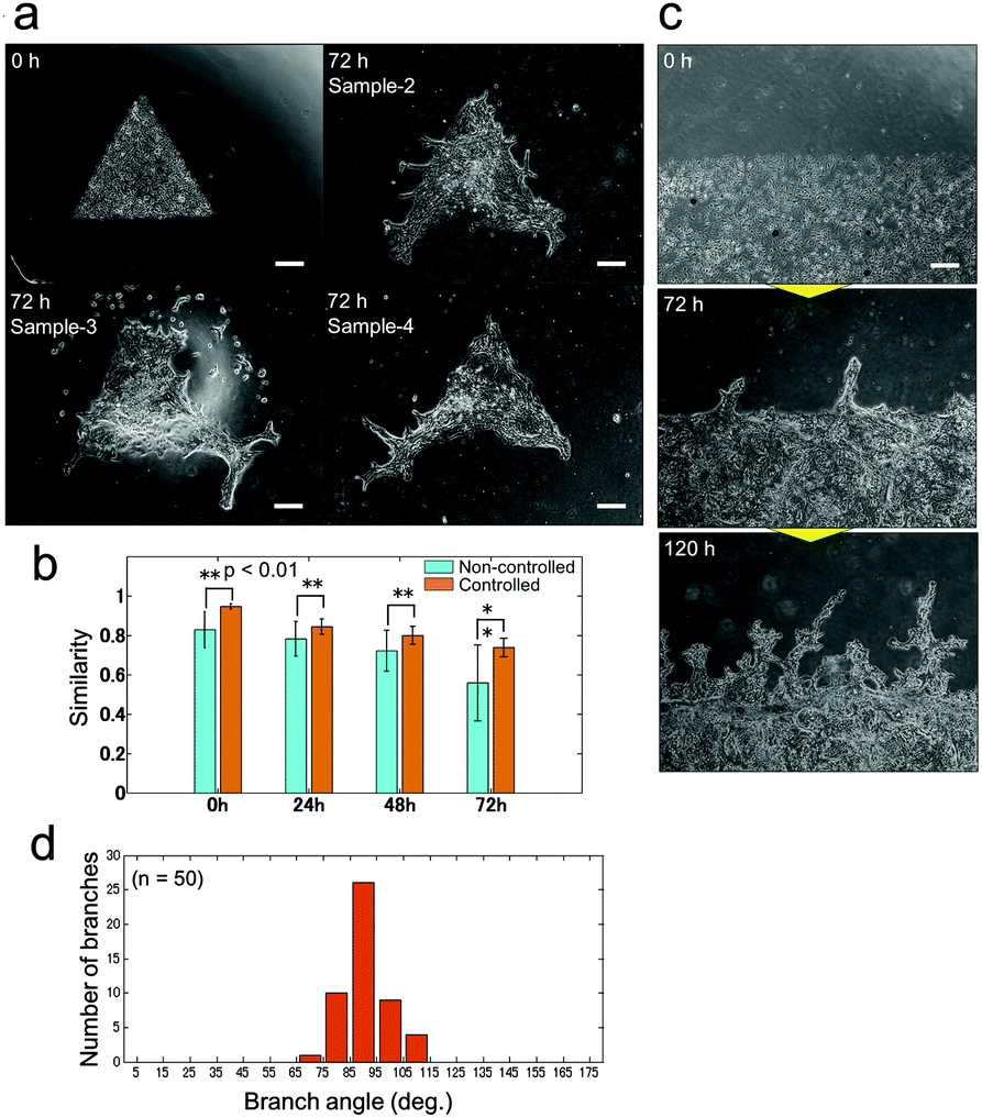 | ||
| Fig. 3 Pattern formations by collective cells of bronchial epithelia developed from the controlled initial culture conditions. (a) Pattern formations starting from triangle shapes at 0 hours (upper left) and 3 samples after 72 hours of culture. Branch shapes were generated at all tips of the triangle shapes and the characteristics of the pattern are similar for all samples. Scale bar, 300 μm. (b) The similarity of the developed pattern starting from controlled initial culture conditions by photolithography and from non-controlled culture at 0 hours, 24 hours, 48 hours, and 72 hours. The repeatability of the pattern formation was higher under the controlled conditions than without control at all points (p < 0.01). The similarity was calculated by normalized cross-correlation after the image changed to the binary image (Fig. S5, ESI†). (c) Pattern formation starting from aligned collective cells in a long straight line. Scale bar, 500 μm. (d) Histogram of the initial branching angle starting from a long straight line. The direction tended to be perpendicular to the original straight line (n = 50). | ||
In silico experiments involving the RD model for branching pattern formation
The advantage of controlling the initial culture conditions is that not only can the experimental noise be reduced but the experimental conditions can also be matched with the simulation conditions. This allows the model to obtain fair feedback from experiments to refine the model parameters. If the model can achieve reasonable agreement with the experimentally obtained pattern formation under multiple initial conditions with fixed parameters, it can be justified that the physical phenomena accounted for in the model are weighted more among the potential factors. Once the model is experimentally validated, dynamic simulations can be conducted to decode the logic underlying the system of multicellular pattern formation.The RD model is a mathematical model used to simulate self-organized pattern formation by computing the spatial distributions and dynamic reaction of secreted morphogens.22,27 However, there tends to be a gap between mathematical models and in vitro experimental research due to incongruity between the idealized conditions of the theoretical model and the actual experimental conditions. Now that the experimental conditions can be controlled and only epithelial cells are used for epithelial pattern formation, the conditions of in vitro experiments can step much closer to the idealized in silico experiments. The in vitro experimental system is suitable for the validation of whether the RD model can describe the mechanisms that underlie pattern formation by collective cell migration in bronchial epithelia.
The RD model proposed by H. Meinhardt23 was examined to simulate the pattern formation developed by the collective cells of bronchial epithelia. To express the inherent variation in the system, 7% random fluctuation was included in the morphogen’s reaction rate parameter (c in eqn (1) and (2)). After repetitive feedback from experimental patterns starting from multiple geometries to refine the parameters, the simulated patterns reached good agreement with actual branch formation (Fig. 4(a)). The characteristics of the branch shape patterns, such as the position and direction of collective cell migrations, corresponded to those observed in experiments under all conditions, and the direction of collective cell migration tended to be perpendicular to the original edge line. Except for the parameter with random fluctuation, the parameters used in the model were fixed for all geometrical conditions. The cellular dynamics in NHBEs were also observed by time-lapse imaging, which showed that cells migrated to the tips of the triangle geometry and there were fewer cells at the center of the triangle (Fig. 4(b) and Video 2, ESI†). Then, the triangle shape was reconstructed followed by collective migration to form branched shape patterns at the tips. The same tendency could be observed in the simulation as well (Fig. 4(c) and Video 3, ESI†). The value of biomarker Y in the RD model indicated that the position of the collective cells is fixed if Y becomes higher than the threshold (red area in Fig. 4(c) and Video 3, ESI†) and is still variable if the Y value is lower than the threshold (blue area in Fig. 4(c) and Video 3, ESI†). The static and dynamic results indicate that the RD system is the major physical mechanism that determines the branch shape formation of collective bronchial epithelial cells.
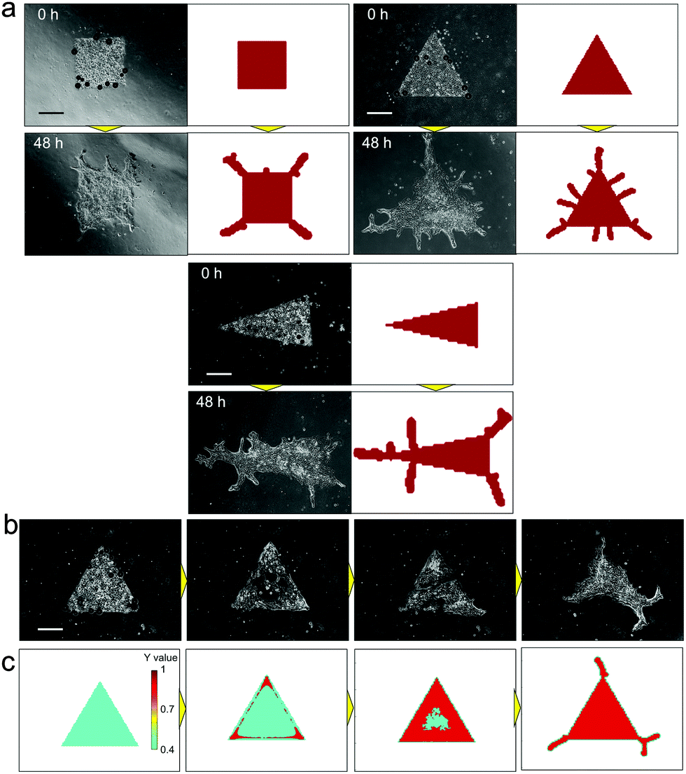 | ||
| Fig. 4 Comparison of branch shape pattern formation between in vitro experimental results and the simulated pattern by the reaction-diffusion model. (a) Comparison of the branched pattern starting from multiple initial conditions. After repetitive feedbacks from in vitro experiments to refine the parameters, the simulated patterns reached good agreement with actual branch formation under all conditions. The characteristics of the initial branched pattern, such as the position and direction, corresponded to those in experiments under all conditions, and branching occurred at the tips of the initial geometries. The direction tended to be perpendicular to the original edge line. (b) Time lapse imaging of branching morphogenesis in vitro, starting from the triangle shape. Cells migrated to the tips of the triangle shape at the beginning, and there were lesser number of cells at the center of the initial triangle shape. Then, the cells reconstructed the triangle shape and developed branches at tips (Video 2, ESI†). (c) Simulated dynamics of the biomarker Y value. The same tendency as in (b) can be observed by RD simulations. The Y value was higher at the tips and at the edge of the triangle at the beginning, which indicates that cells move to the edge at first. Then, the triangle center became higher and branching was initiated from tips (Video 3, ESI†). Scale bars, 500 μm. | ||
Spatiotemporal analysis of morphogen distribution for branching pattern formation
Once the mathematical model is verified and the simulation accuracy is improved by refining the parameters, the model can be used for the spatiotemporal analysis of morphogen distribution, which cannot be done in cell culture experiments, in order to uncover the logic underlying the system determining pattern formation. In the RD model, the activator and inhibitor are the main factors involved in the self-organization of pattern formation. The activator drives cells to migrate and/or proliferate and increases the amount of the activator by an autocatalytic function as well as increasing the amount of inhibitor, while the inhibitor represses activator function. To develop self-organized pattern formation, short-range activation and long-range inhibition are required;28 that is, the activator diffusion rate must be lower than the inhibitor diffusion rate.First, the reason why 2D pattern formation of collective bronchial epithelial cells can be developed only when cells are set on a dish with a high cell concentration gradient covered by an ECM can be explained by the RD model (Fig. 5(a–c)). When cells are set on a dish without an ECM, the diffusion rates of the activator and inhibitor are inversely proportional to their molecular sizes and the molecular weights are usually in the same order. If the diffusion rate of the inhibitor is not high enough to spatially restrict the activator function, the cells grow homogeneously (Fig. 5(a) and Video 4, ESI†). On the other hand, if the cells are covered by the ECM, the fiber network structure in the ECM hinders molecular diffusion and increases differences between the diffusion rates of the activator and inhibitor. However, although the ECM was coated onto the cells, the inhibitor secreted from the cells interrupted the growth of the surrounding cells when they were homogeneously distributed (Fig. 5(b)). Under these conditions, the inhibitor was present in the entire culture area and therefore the cells could not undergo directional migration. By contrast, the effect of short-range activation can be enhanced by setting the cells at a single point while the interruption of long-range inhibition from neighbour cells is kept the same. As a result, branches can be developed under the limited condition that cells are set with a high concentration gradient covered by the ECM (Fig. 5(c) and Video 5, ESI†).
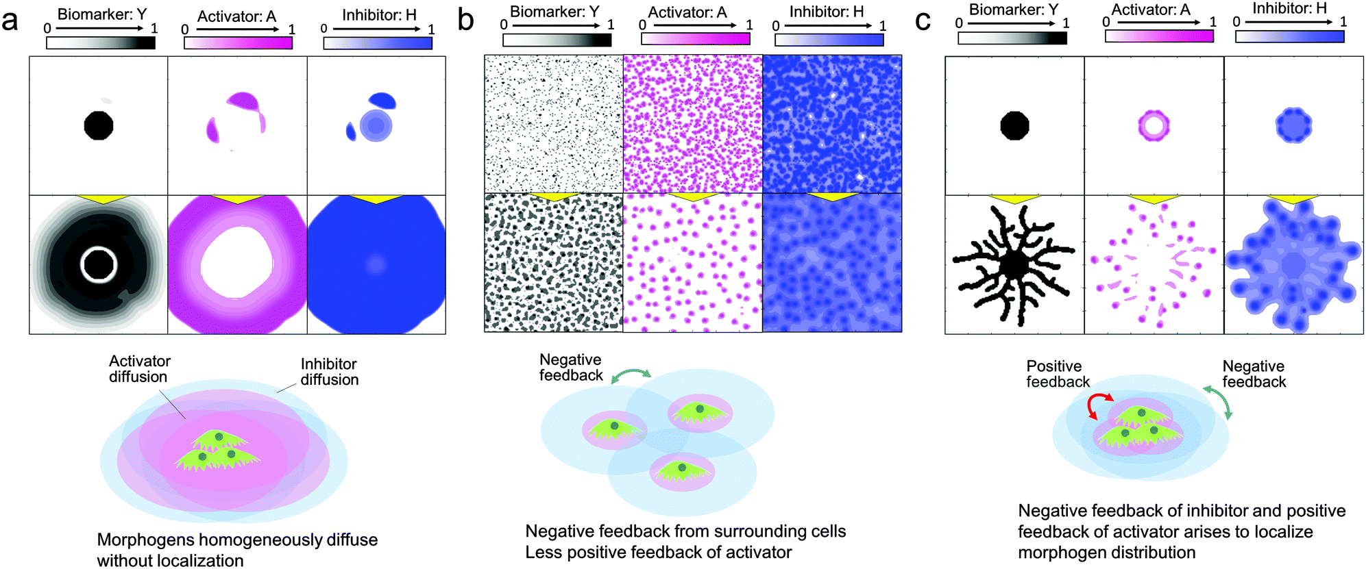 | ||
| Fig. 5 Morphogen distribution computed by the RD model for analyzing why 2D branching morphogenesis can be developed only when NHBEs are set on a dish with a high cell concentration gradient covered by an ECM. (a) When cells are placed at a high concentration gradient without the ECM, the differences in diffusion rates of the activator and inhibitor are too small to generate branch patterns (Video 4, ESI†). (b) When cells are homogeneously distributed, they are interrupted by long-range inhibition from surrounding cells and collective cell migration is restricted. (c) When cells placed at a high concentration gradient were covered by the ECM, branch patterns could be generated (Video 5, ESI†). | ||
Next, to investigate the logic of why initial collective cells tend to migrate in a perpendicular direction at a specific position, a dynamic simulation of morphogens was performed using the RD model (Fig. 6(a) and Video 6, ESI†). Molecules, in general, diffuse from an area of higher concentration to an area of lower concentration. Therefore, when the collective cells are aligned in a straight line, as shown in Fig. 4(d), morphogens secreted from cells diffused in a direction perpendicular to the edge of the collective cells, which leads cells to likewise grow in a direction perpendicular to the edge of the collective cells. In addition, the relationship between activator and inhibitor diffusion rates results in determining the position of collective cell migration to form a branch shape. The activator concentration slightly varied along the edge of the collective cells due to the inherent variation in cell viability. Once the activator concentration increased at a certain spot, the concentration rapidly increased further because of autocatalysis at that spot (Fig. 6(b), Fig. S4 and Video 7, ESI†). The inhibitor concentration was also increased by the activator at that spot. Because of long-range inhibition and short-range activation, the inhibitor suppressed the activator concentration within a broad range. As a consequence, the activator concentration near the activator peak was lower than that at other positions. Therefore, cells could not grow near a branch and the subsequent branches were generated while maintaining a certain distance from the other branches.
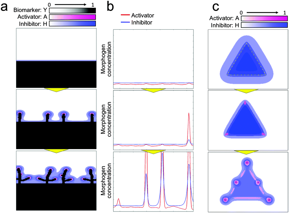 | ||
| Fig. 6 Dynamic morphogen analysis by the RD model for branching pattern formation. (a) RD simulation starting from a long straight line. Morphogens secreted by cells diffused in the perpendicular direction since molecules diffuse more through a high-gradient path so that the cells grow in a perpendicular direction (Video 6, ESI†). (b) 1D simulation of morphogen dynamics at the edge of the collective cell boundary aligned with the straight line. Inherent fluctuation of cell activity was enhanced by the autocatalytic function of the activator to generate a steep activator concentration peak. The inhibitor was also amplified by the activator at the peak point; the activator concentration near the peak point was reduced due to long-range inhibition to regulate branching (Fig. S4 and Video 7, ESI†). (c) Activator and inhibitor concentration dynamics when cells were set in a triangle shape. Initially, the inhibitor concentration was higher at the center of the triangle but relatively lower at the tips of the triangles. The effect of the activator then relatively increased to generate branches at the tips (Video 8, ESI†). | ||
The logic of why branches were generated at the tips of the collective cell geometries and why the cells faded away from the center of collective cells at the beginning (Fig. 4(b and c)) was also analysed by dynamically simulating the morphogen distribution (Fig. 6(c) and Video 8, ESI†). The relationship between the diffusion rates of the activator and inhibitor is again a key factor here. The effect of the inhibitor is widespread due to the high diffusion rate. Therefore, the inhibitor concentration is higher at the center of the collective cells because the number of surrounding cells is higher while the concentration is lower at the tips of the collective cell geometries because of the presence of a much lesser number of surrounding cells. On the other hand, the effect of the activator is spatially limited due to its low diffusion rate and its concentration does not depend on the number of surrounding cells. As a result, the effect of the activator is relatively higher at the tips of the collective cell geometries and the activator concentration there increases at the beginning, followed by an increase in the concentration of the activator at the edge due to the low concentration of the inhibitor. Then, cells tend to move to either the tips or edges of the collective cell geometries to avoid areas containing a high concentration of inhibitor, and directional migration of the collective cells was generated at the tips first, as shown in Fig. 4(b and c).
Discussion
In this paper, a 2D in vitro experimental model of bronchial epithelial cells to form a pattern was developed. When cells were placed at a spot and covered by the ECM, the collective cells underwent directional migration. The pattern of the bronchial epithelial cells developed bifurcations and formed “branch” shapes. The advantages of this experimental model are that patterns can be generated from epithelial cells alone and the initial cell conditions can easily be controlled by photolithography on a substrate. Therefore, the experimental conditions can be engineered to bring them closer to the idealized theoretical conditions and the experimental model is suitable for analysing the mechanisms of pattern formation by collective cell migration. Spatiotemporal analysis of molecular dynamics based on a RD model after multiple feedbacks of in vitro and in silico experiments revealed that differences in the diffusion rate of morphogens determined the position and direction of the collective cell migration. The long-range inhibition and short-range activation systems played a key role in branch shape formation by the collective cells.The paper focused on an RD system to generate the pattern formation, but many other phenomena such as mechanical interactions between cells are also simultaneously generated to affect cellular dynamics and pattern formation. For example, the collective cells shrunk from the original triangle shape in Fig. 3a and 4b, which cannot be expressed in the RD simulation, and this phenomenon should be generated by force interactions. By incorporating these factors in the model, the simulation can describe more realistic dynamics.
The experiments described in this paper focused on pattern formation resulting from the collective cell migration of NHBEs, while the pattern formation of lung branching in the body is based on 3D morphogenesis. In 3D branch formation, various physical phenomena such as the folding process of epithelial sheets29–31 occur to form branching morphogenesis. Therefore, the mechanisms of monolayer pattern formation presented represent the fundamental drivers of the sophisticated physiological pattern of lung branching, but the developed experimental system and results cannot be directly applied to the actual lung pattern. On the other hand, it is interesting that the pattern that developed in 2D still had a “branched” shape with multiple bifurcations. The results indicate the possibility that the collective cell migration governed by an activator–inhibitor system has a certain contribution to the 3D pattern formation of lung branches. The key morphogens in the RD system of lung branching pattern formation have not been identified yet,19 but many previous studies have indicated that sonic hedgehog (SHH), bone morphogenetic protein 4 (BMP4), fibroblast growth factor 10 (FGF10), and sprouty 2 (SPRY2) are the morphogen candidates. By further elucidating the key morphogens, we can move forward to a fuller understanding of lung branch pattern formation.
Conclusions
It is possible to validate whether the physical dynamics described in the mathematical model are dominant determinants of pattern formation by using an interface that brings the in vitro experimental environment closer to the in silico experimental environment. Simple but robust engineering technology significantly helps to bridge the in silico and in vitro experiments by reducing experimental variation and noise in vitro. In addition, the accuracy of the simulation can be improved considerably by repetitive feedback from pattern formation developed in vitro under multiple different initial conditions. Then, spatiotemporal analysis of molecular dynamics would become the most powerful tool for elucidating the logic of pattern formation, as presented in this paper. Moreover, an accurate mathematical model has the potential to aid in designing initial culture conditions so as to lead cells toward specific multicellular pattern formation for the regeneration of complex tissues in vitro by solving the inversion problem. In addition, engineering technologies such as design principles and control theories will be increasingly required. The current findings emphasize that the synthesis of different approaches such as those involving biology, mathematics, physics, and engineering would aid in resolving complex questions in biological studies and bring us forward to the study of new fields.Acknowledgements
This work was financially supported by a Grant-in-Aid for Young Scientists (A), Challenging Exploratory Research from the Japan Society for the Promotion of Science (15K13325, 15H05512), The Nakajima Foundation and the Program to Disseminate Tenure Track System, MEXT, Japan.Notes and references
- J. Stelling, U. Sauer, Z. Szallasi, F. J. Doyle and J. Doyle, Cell, 2004, 118, 675–685 CrossRef CAS PubMed.
- Y. Sasai, Nature, 2013, 17, 318–326 CrossRef PubMed.
- F. Xiong, W. Ma, T. W. Hiscock, K. R. Mosaliganti, A. R. Tentner, K. A. Brakke, N. Rannou, A. Gelas, L. Souhait, I. A. Swinburne, N. D. Obholzer and S. G. Megason, Cell, 2014, 159, 415–427 CrossRef CAS PubMed.
- C. J. Weijer, J. Cell Sci., 2009, 122, 3215–3223 CrossRef CAS PubMed.
- K. Doxzen, S. R. Vedula, M. C. Leong, H. Hirata, N. S. Gov, A. J. Kabla, B. Ladoux and C. T. Lim, Integr. Biol., 2013, 8, 1026–1035 RSC.
- E. Méhes and T. Vicsek, Integr. Biol., 2014, 6, 831–854 RSC.
- A. Haeger, K. Wolf, M. M. Zegers and P. Friedl, Trends Cell Biol., 2015, 25, 556–566 CrossRef PubMed.
- K. Sato, T. Hiraiwa, E. Maekawa, A. Isomura, T. Shibata and E. Kuranaga, Nat. Commun., 2015, 6, 10074 CrossRef CAS PubMed.
- R. J. Metzger, O. D. Klein, G. R. Martin and M. A. Krasnow, Nature, 2008, 453, 745–750 CrossRef CAS PubMed.
- M. Weaver, N. R. Dunn and B. L. Hogan, Development, 2000, 127, 2695–2704 CAS.
- T. Onodera, S. Takayoshi, J. C. Hsu, K. Matsumoto, J. A. Chiorini and K. M. Yamada, Science, 2010, 329, 562–565 CrossRef CAS PubMed.
- A. Lazarus, P. M. Del-Moral, O. Ilovich, E. Mishani, D. Warburton and E. Keshet, Development, 2011, 138, 2359–2368 CrossRef CAS PubMed.
- M. Herriges and E. E. Morrisey, Development, 2014, 141, 502–513 CrossRef CAS PubMed.
- T. Miura, J. Biochem., 2015, 157, 121–127 CrossRef CAS PubMed.
- S. R. Lubkin and J. D. Murray, J. Math. Biol., 1995, 34, 77–94 CrossRef CAS PubMed.
- K. A. Moore, T. Polte, S. Huang, B. Shi, E. Alsberg, M. E. Sunday and D. E. Ingber, Dev. Dyn., 2005, 232, 268–281 CrossRef CAS PubMed.
- T. Miura and K. Shiota, Mech. Dev., 2002, 116, 29–38 CrossRef CAS PubMed.
- D. Menshykau, C. Kraemer and D. Iber, PLoS Comput. Biol., 2012, 8, e1002377 CAS.
- Y. Guo, T. H. Chen, X. Zeng, D. Warburton, K. I. Boström, C. M. Ho, X. Zhao and A. Garfinkel, J. Physiol., 2014, 592, 313–324 CrossRef CAS PubMed.
- M. M. Zegers, L. E. O’Brien, W. Yu, A. Datta and K. E. Mostov, Trends Cell Biol., 2003, 13, 169–176 CrossRef CAS PubMed.
- A. J. Ewald, A. Brenot, M. Duong, B. S. Chan and Z. Werb, Dev. Cell, 2008, 14, 570–581 CrossRef CAS PubMed.
- A. M. Turing, Philos. Trans. R. Soc. London, Ser. B, 1952, 237, 37 CrossRef.
- H. Meinhardt, Differentiation, 1976, 6, 117–123 CrossRef CAS PubMed.
- M. Hagiwara, F. Peng and C. M. Ho, Sci. Rep., 2015, 5, 8054 CrossRef CAS PubMed.
- M. Reffay, M. C. Parrini, O. Cochet-Escartin, B. Ladoux, A. Buguin, S. Coscoy, F. Amblard, J. Camonis and P. Silberzan, Nat. Cell Biol., 2014, 16, 217–223 CrossRef CAS PubMed.
- N. Yamaguchi, T. Mizutani, K. Kawabata and H. Haga, Sci. Rep., 2015, 5, 7656 CrossRef CAS PubMed.
- S. Kondo and T. Miura, Science, 2010, 329, 1616 CrossRef CAS PubMed.
- A. Nakamasu, G. Takahashi, A. Kanbe and S. Kondo, Proc. Natl. Acad. Sci. U. S. A., 2009, 106, 8429–8434 CrossRef CAS PubMed.
- M. Tawk, C. Araya, D. A. Lyons, A. M. Reugels, G. C. Girdler, P. R. Bayley, D. R. Hyde, M. Tada and J. D. W. Clarke, Nature, 2007, 446, 797–800 CrossRef CAS PubMed.
- T. Lecuit and P. F. Lenne, Nat. Rev. Mol. Cell Biol., 2007, 8, 633–644 CrossRef CAS PubMed.
- E. Hannezo, J. Prost and J. F. Joanny, Proc. Natl. Acad. Sci. U. S. A., 2014, 111, 27–32 CrossRef CAS PubMed.
Footnote |
| † Electronic supplementary information (ESI) available: Supplementary data and 8 multimedia files showing the dynamics of experimental results as well as simulation results. See DOI: 10.1039/c6ib00073h |
| This journal is © The Royal Society of Chemistry 2016 |