 Open Access Article
Creative Commons Attribution 3.0 Unported Licence
Supported molybdenum oxides as effective catalysts for the catalytic fast pyrolysis of lignocellulosic biomass†
Karthick
Murugappan
a,
Calvin
Mukarakate
b,
Sridhar
Budhi
b,
Manish
Shetty
a,
Mark R.
Nimlos
 *b and
Yuriy
Román-Leshkov
*a
aDepartment of Chemical Engineering, Massachusetts Institute of Technology, Cambridge, MA 02139, USA. E-mail: yroman@mit.edu
bNational Renewable Energy Laboratory, 15523 Denver West Parkway, Golden, CO 80401-3393, USA. E-mail: Mark.Nimlos@nrel.gov
First published on 12th July 2016
Abstract
The catalytic fast pyrolysis (CFP) of pine was investigated over 10 wt% MoO3/TiO2 and MoO3/ZrO2 at 500 °C and H2 pressures ≤0.75 bar. The product distributions were monitored in real time using a molecular beam mass spectrometer (MBMS). Both supported MoO3 catalysts show different levels of deoxygenation based on the cumulative biomass to MoO3 mass ratio exposed to the catalytic bed. For biomass to MoO3 mass ratios <1.5, predominantly olefinic and aromatic hydrocarbons are produced with no detectable oxygen-containing species. For ratios ≥1.5, partially deoxygenated species comprised of furans and phenols are observed, with a concomitant decrease of olefinic and aromatic hydrocarbons. For ratios ≥5, primary pyrolysis vapours break through the bed, indicating the onset of catalyst deactivation. Product quantification with a tandem micropyrolyzer–GCMS setup shows that fresh supported MoO3 catalysts convert ca. 27 mol% of the original carbon into hydrocarbons comprised predominantly of aromatics (7 C%), olefins (18 C%) and paraffins (2 C%), comparable to the total hydrocarbon yield obtained with HZSM-5 operated under similar reaction conditions. Post-reaction XPS analysis on supported MoO3/ZrO2 and MoO3/TiO2 catalysts reveal that ca. 50% of Mo surface species exist in their partially reduced forms (i.e., Mo5+ and Mo3+), and that catalyst deactivation is likely associated to coking.
1. Introduction
The demand for the production of renewable transportation fuels and chemicals from lignocellulosic biomass has increased over the last decade in our efforts to lower the carbon footprint of the transportation and chemicals sectors. Among the many conversion technologies currently available, fast pyrolysis has emerged as a promising avenue to convert low energy density biomass to higher energy density liquid bio-oils with typical yields of ca. 65 wt%.1–3 However, these bio-oils cannot be directly used as or blended with transportation fuels due to their high oxygen, water, and acid content.4,5 As a result, a catalytic upgrading step to deoxygenate and stabilise bio-oil is required before it can be processed with regular transportation fuels. Recently, increasing research efforts have focused on catalytic fast pyrolysis (CFP)—a single step bio-oil upgrading process wherein the hot pyrolysis vapours are contacted with a catalytic bed prior to condensation.6–9 CFP is a promising alternative to the conventional two-step bio-oil upgrading process as it is simpler and avoids cumbersome condensation and re-evaporation steps.8–10Ex situ CFP takes place when the pyrolysis and upgrading processes are decoupled by placing a catalytic bed downstream of the pyrolysis reactor.7 In contrast, during in situ CFP, the feedstock is mixed with the upgrading catalyst prior to heating.7 Both strategies have been shown to produce higher quality bio-oils than the non-catalytic pyrolysis process.6 Although in situ CFP features more intimate contact between biomass and the catalyst, the catalyst is exposed to char and ash, which can be detrimental to the catalyst performance.11,12 Recent techno-economic and uncertainty analyses have also indicated that the ex situ operating mode could offset more commercialisation risks than the in situ mode.12Proton-exchanged zeolites, such as HZSM-5, are the state-of-the-art catalysts used for the production of hydrocarbons from biomass via CFP.8,13–17 Although gasoline-range aromatics are obtained with these materials, typically low carbon yields, high light gas production, and rapid catalyst deactivation due to coking are observed.13,18,19 These shortcomings are a consequence of the inherently hydrogen deficient nature of lignocellulosic biomass (it features an effective hydrogen to carbon ratio ranging from 0 to 0.3)20 coupled with the lack of external H2 gas addition to the process, which forces high degrees of deoxygenation to occur by decarbonylation, decarboxylation, dehydration and coking. As such, large catalyst quantities are needed to achieve high conversions.13,21–24 Indeed, the development of alternative CFP catalysts that can overcome these technical barriers remains an important challenge.
Hydrodeoxygenation (HDO) is a common upgrading strategy that uses hydrogen to remove oxygen selectively as water without breaking molecular carbon backbones. Recently, Román-Leshkov et al. showed that molybdenum trioxide (MoO3) is an effective HDO catalyst that produces olefinic and aromatic hydrocarbons at high selectivities (>97%) from various biomass-derived oxygenates under mild conditions (T = 320 °C and PH2 ≤ 1 bar).25,26 These studies revealed that Mo5+ species were important for maintaining the activity of the catalyst over extended time periods and were stabilised by a partial carburisation of the surface that prevented over-reduction to less reactive Mo4+ species.26 Coupled reactivity and characterisation studies showed that dispersing MoO3 on high surface area oxides, such as ZrO2 and TiO2, significantly improved both the reactivity and stability of the catalyst during the HDO of m-cresol.27 An oxygen vacancy driven mechanism was hypothesised to be responsible for the HDO of oxygenates over both bulk and supported MoO3 catalysts.25,27 Similarly, Bhan and co-workers have shown that a combination of metallic and Brønsted acid sites in partially oxidized molybdenum carbide can effectively hydrodeoxygenate biomass-derived molecules using atmospheric H2 pressures and low temperatures (420–520 K).28–31
MoO3 has been tested in CFP of lignocellulosic biomass with some success. Budhi et al. investigated molybdenum supported on KIT-5 mesoporous silica for the CFP of pine in the absence of H2 gas.32 The catalysts preferentially produced furans and phenols with small amounts of aromatic hydrocarbons.32 Nolte et al. performed CFP of cellulose, lignin, and corn stover in a tandem micropyrolyzer using bulk MoO3 at low H2 pressures and cumulative biomass![[thin space (1/6-em)]](https://www.rsc.org/images/entities/char_2009.gif) :
:![[thin space (1/6-em)]](https://www.rsc.org/images/entities/char_2009.gif) catalyst ratios of ca. 0.006, mainly producing linear alkanes and aromatics.33 Although the HDO of model compounds has been demonstrated with supported MoO3 catalysts, the performance and stability of these catalysts have not been investigated for the CFP of lignocellulosic biomass using atmospheric hydrogen pressures.
catalyst ratios of ca. 0.006, mainly producing linear alkanes and aromatics.33 Although the HDO of model compounds has been demonstrated with supported MoO3 catalysts, the performance and stability of these catalysts have not been investigated for the CFP of lignocellulosic biomass using atmospheric hydrogen pressures.
In this contribution, 10 wt% MoO3 supported on TiO2 and ZrO2 catalysts are investigated for the CFP of pine at 500 °C and H2 pressures ≤0.75 bar. A 10 wt% MoO3 loading was used to obtain a near-monolayer coverage of oligomeric molybdena species on the surface of the support, as reported by Shetty et al. during the HDO of m-cresol.27 This study also showed that oligomeric molybdena species supported on TiO2 and ZrO2 were the optimal supports for HDO of all oxide supports investigated.27 For this reason, 10 wt% MoO3/TiO2 and MoO3/ZrO2 catalysts were selected for this work. Catalyst HDO performance is monitored in real time by coupling an ex situ catalytic fast pyrolysis unit with a molecular beam mass spectrometer (MBMS). An ex situ processing mode was selected to independently study the effect of the catalyst on the hydrodeoxygenation of pyrolysis vapours.11 We use a multivariate analysis of the MBMS data to group products with varying degrees of deoxygenation into “bins”, which are then tracked as a function of the cumulative amount of pyrolysis vapours exposed to the catalytic bed for biomass![[thin space (1/6-em)]](https://www.rsc.org/images/entities/char_2009.gif) :
:![[thin space (1/6-em)]](https://www.rsc.org/images/entities/char_2009.gif) MoO3 mass ratios ranging from 0 to 20. These data are complemented by detailed product identification and quantification using a tandem micropyrolyzer–Gas Chromatography Mass Spectrometry (GCMS) system. The catalysts are compared to a state-of-the-art acid zeolite with the MFI topology (HZSM-5) tested in the micropyrolyzer–GCMS system under similar reaction conditions. The spent catalysts are then characterised using powder X-ray diffraction (PXRD) and X-ray photoelectron spectroscopy (XPS) to provide insights on the changes in the bulk structure and stabilisation of specific surface Mo oxidation states, respectively.
MoO3 mass ratios ranging from 0 to 20. These data are complemented by detailed product identification and quantification using a tandem micropyrolyzer–Gas Chromatography Mass Spectrometry (GCMS) system. The catalysts are compared to a state-of-the-art acid zeolite with the MFI topology (HZSM-5) tested in the micropyrolyzer–GCMS system under similar reaction conditions. The spent catalysts are then characterised using powder X-ray diffraction (PXRD) and X-ray photoelectron spectroscopy (XPS) to provide insights on the changes in the bulk structure and stabilisation of specific surface Mo oxidation states, respectively.
2. Experimental
2.1 Materials and synthesis
Southern yellow pine (42% cellulose, 21% hemicellulose, and 30% lignin) supplied by Idaho National Laboratory was used as lignocellulosic biomass feedstock for all the experiments.13 The C, H and N contents were measured using a LECO TruSpec CHN module, as discussed previously,34 and the oxygen content was measured by difference. The elemental analysis on a dried biomass sample showed that it contains 50% carbon, 43% oxygen, 6% hydrogen, and less than 1% nitrogen. The moisture content was 2%. Bulk molybdenum(VI) oxide (MoO3, ≥99.5%), molybdenum(IV) oxide (MoO2, ≥99 wt%), and molybdenum carbide (Mo2C, ≥99.5 wt%) were purchased from Sigma-Aldrich. Molybdenum powder (99.9 wt%) was purchased from Alfa Aesar, and HZSM-5, with a silica-to-alumina ratio (SAR) of 30 and 20 wt% silica binder, was purchased from Nexceris. Titanium(IV) oxide (TiO2, anatase phase, 21 nm, ≥99.5 wt%, Sigma Aldrich) was used directly as a support while zirconium(IV) oxide (ZrO2) nanoparticles were synthesised using previously reported methods.35 Supported 10 wt% MoO3/TiO2 and MoO3/ZrO2 were prepared by wet impregnation of aqueous solutions of ammonium paramolybdate tetra(para)hydrate ((NH4)6Mo7O24·4H2O, 99%, Alfa Aesar) as described previously.27 Catalysts were sieved to 500–1000 μm pellets before use in the CFP experiments.2.2 Catalytic fast pyrolysis
![[thin space (1/6-em)]](https://www.rsc.org/images/entities/char_2009.gif) :
:![[thin space (1/6-em)]](https://www.rsc.org/images/entities/char_2009.gif) catalyst ratio. Further details on the application of multivariate analysis can be found in previous reports.36,37
catalyst ratio. Further details on the application of multivariate analysis can be found in previous reports.36,37
The furnace heat transfer rates in both the reactor configurations are comparable to that typically seen for fast pyrolysis. Although no direct measurement of the pine heating rate was performed in the current study, both the horizontal reactor and the micropyrolyzer were connected to the MBMS in two separate experiments. In both cases, the pyrolysis products appeared within 1–2 seconds after introducing the pine boat into the reactors set to 500 °C. The total mass spectral ion counts, which can be used to profile the duration of pyrolysis of each boat, took on average 33 seconds. Based on the rise time to peak pyrolysis vapour evolution observed by the total mass spectral ion count curves, the heating rates were estimated to be greater than 30 °C s−1, which are typical for fast pyrolysis. Similar conclusions for fast pyrolysis have been reported for such reactor configurations in a previous study.36
2.3 Spent catalyst characterisation
PXRD patterns were collected using a Bruker D8 diffractometer with nickel-filtered Cu–Kα radiation (λ = 1.5418 Å). Diffraction data were recorded on a 2D image plate rotated at a speed of 15 rpm, between 2θ values of 20–90° with a step size of 0.2° s−1.XPS spectra were collected on a PHI Versaprobe II instrument equipped with a multi-channel hemispherical analyser and an aluminum anode X-ray source operating at 100 W, featuring a 100 μm beam scanned over a 1.4 mm line across the sample surface. A dual-beam charge neutralisation system was used with an electron neutraliser bias of 1.2 eV and an Ar ion beam energy of 10 eV. The spent catalysts were mixed with niobium oxide (Nb2O5, 99.99%, Sigma Aldrich) as an internal standard for charge correction. The binding energies were corrected to 207.4 eV (Nb 3d5/2). A 7-point Shirley background correction was then applied to the Mo 3d XPS spectra after charge correction. The Mo 3d spectra were deconvoluted to estimate the composition of Mo oxidation states. The following constraints were used for deconvolution: (1) a splitting energy of 3.15 eV for Mo 3d5/2–Mo 3d3/2, (2) an area intensity ratio of 3![[thin space (1/6-em)]](https://www.rsc.org/images/entities/char_2009.gif) :
:![[thin space (1/6-em)]](https://www.rsc.org/images/entities/char_2009.gif) 2 for Mo 3d5/2–Mo 3d3/2, and (3) an equal full width at half maximum (FWHM) of Mo 3d5/2 and Mo 3d3/2.
2 for Mo 3d5/2–Mo 3d3/2, and (3) an equal full width at half maximum (FWHM) of Mo 3d5/2 and Mo 3d3/2.
The amount of carbonaceous species on the spent supported MoO3 catalysts was quantified using a CHNS analyser (Elementar, Vario EL cube). Sulfanilamide was used to calibrate the equipment prior to carbon content measurements. Similarly, coke deposited on the spent HZSM-5 catalyst was quantified by thermogravimetric analysis in a TGA Instruments Q500 analyser using a previously reported protocol.18
3. Results and discussion
3.1 Horizontal reactor–MBMS
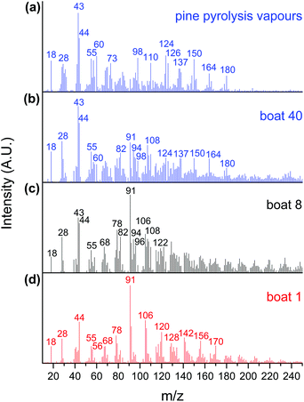
The CFP of pine was investigated in a horizontal reactor–MBMS set up using 10 wt% MoO3/TiO2, 10 wt% MoO3/ZrO2, and bulk MoO3 catalysts. A total of 40 quartz boats containing 50 mg of pine per boat were sequentially pyrolysed over 1.0 g of catalyst. Fig. 1(a) shows the mass spectra of a control sample obtained by pyrolysing 50 mg of pine in the absence of a catalyst. As expected, oxygenated hydrocarbons, such as aldehydes, ketones, carboxylic acids, alcohols and phenolics, were detected in addition to water, carbon monoxide and carbon dioxide (m/z 18, 28 and 44). Guaiacol, methyl guaiacol, vinyl guaiacol, isoeugenol and coniferyl alcohol (m/z 124, 137, 150, 164 and 180) are pyrolysis products from the lignin portion of pine, while acetic acid/glycoaldehyde, furfuryl alcohol and levoglucosenone/5-hydroxymethyl furfural (m/z 60, 98 and 126) are pyrolysis products from the cellulose and hemicellulose portions of pine.13 The peaks at m/z 43, 55 and 73 are known carbohydrate fragments.13,36,37Fig. 1(b), (c) and (d) show the products obtained during the CFP of pine using the MoO3/TiO2 catalyst after the 40th, 8th and 1st boat, respectively. The 1st boat was predominantly converted into fully deoxygenated products, including alkenes (butene, m/z 56) and aromatic hydrocarbons such as benzene, toluene, xylenes, trimethylbenzenes, naphthalene, methylnaphthalenes, dimethylnaphthalenes and trimethylnaphthalenes (m/z 78, 91, 106, 120, 128, 142, 156 and 170).13 A carbohydrate-based fragment (m/z 55) and furan (m/z 68) were also detected. After the 8th boat, additional peaks corresponding to methyl furan, dimethyl furan, phenol, cresol and xylenol (m/z 82, 96, 94, 108 and 122) were detected.13,32 These furanic and phenolic components are likely partially hydrodeoxygenated intermediates formed during the CFP of pine with a catalyst bed that has begun deactivating.13 The spectrum obtained after the 40th boat mostly shows peaks analogous to those observed during the control experiment with no catalyst, including peaks associated with primary pyrolysis vapours from both lignin (m/z 124, 137, 150, 164, 180) and carbohydrates (m/z 43, 55, 60, 98, 126). The presence of primary pyrolysis components in combination with furans, toluene, and phenol indicates drastic, but not total, catalyst deactivation. Taken together, these data show that the catalyst effectively hydrodeoxygenates pyrolysis vapours into olefinic and aromatic products, but undergoes progressive deactivation that results in products with increasing amounts of oxygen, with increasing cumulative amounts of pyrolysis products in contact with the catalyst bed.
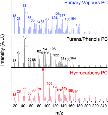
A multivariate analysis was performed to identify, group, and track the relative yield of the hundreds of species produced during the CFP experiments. This analysis allows us to follow the complex change in product distributions as the catalyst undergoes deactivation. Specifically, the MCR-ALS approach reported by Mukarakate et al. and Budhi et al. for tracking the distribution of CFP products over HZSM-513 and BEA zeolites,18 as well as molybdenum supported on mesoporous silica32 was used in the present study to extract pure components from the data set with overlapping mass spectra.32 We used the top 100 masses with the largest variances for each of the 40 boats to produce a 4000-point data set. The objective of MCR is to mathematically decompose our data set of overlapping mass spectra into pure contribution of each component involved during the CFP of the 40 boats.13 We optimised the MCR-ALS analysis for 3 pure components (PCs): hydrocarbons, furans/phenols, and primary vapours. We note that attempts to further increase the number of PCs did not lead to significant changes in the residual error.
Effectively, the MCR-ALS analysis allows us to reconstruct the complex CFP mass spectrum into 3 separate spectra where molecules for each PC are binned (Fig. 2). The hydrocarbons PC is comprised of fully deoxygenated products, including olefins and aromatic hydrocarbons, similar to the products identified after the CFP of the 1st boat (vide supra). The furans/phenols PC represents partially deoxygenated products, including the products observed during the CFP of the 8th boat (methyl furan, dimethyl furan, phenol, cresol, xylenol) as well as trimethylphenol (m/z 136).32 Note that the peaks associated with primary pyrolysis vapours from lignin (m/z 150 and 164) and sugars (m/z 43) are also seen in this PC. The primary vapours PC includes carbohydrate oxygenated fragments, acetic acid/glycoaldehyde, furfuryl alcohol, guaiacol, levoglucosenone or 5-hydroxymethylfurfural, methyl guaiacol, vinyl guaiacol, isoeugenol and coniferyl alcohol.
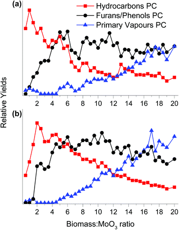
Fig. 3 shows a scores plot for the 3 PCs as a function of the increasing biomass![[thin space (1/6-em)]](https://www.rsc.org/images/entities/char_2009.gif) :
:![[thin space (1/6-em)]](https://www.rsc.org/images/entities/char_2009.gif) MoO3 mass ratio for both MoO3/TiO2 and MoO3/ZrO2 catalysts. Initially, only products associated with the hydrocarbons PC are observed for both catalysts, demonstrating their capability of fully deoxygenating the primary pyrolysis vapours of pine. This behaviour is similar to that of HZSM-5 during the CFP of pine performed in the horizontal reactor–MBMS set up as reported previously.13 Note that for HZSM-5, aromatic hydrocarbons such as benzene, toluene, xylene and naphthalene are produced as major products.13 The intensity of the hydrocarbons PC increases until biomass
MoO3 mass ratio for both MoO3/TiO2 and MoO3/ZrO2 catalysts. Initially, only products associated with the hydrocarbons PC are observed for both catalysts, demonstrating their capability of fully deoxygenating the primary pyrolysis vapours of pine. This behaviour is similar to that of HZSM-5 during the CFP of pine performed in the horizontal reactor–MBMS set up as reported previously.13 Note that for HZSM-5, aromatic hydrocarbons such as benzene, toluene, xylene and naphthalene are produced as major products.13 The intensity of the hydrocarbons PC increases until biomass![[thin space (1/6-em)]](https://www.rsc.org/images/entities/char_2009.gif) :
:![[thin space (1/6-em)]](https://www.rsc.org/images/entities/char_2009.gif) MoO3 ratios of 1 and 2 are reached for MoO3/TiO2 and MoO3/ZrO2, respectively, and then decreases gradually. Products associated with furans/phenols start forming at biomass
MoO3 ratios of 1 and 2 are reached for MoO3/TiO2 and MoO3/ZrO2, respectively, and then decreases gradually. Products associated with furans/phenols start forming at biomass![[thin space (1/6-em)]](https://www.rsc.org/images/entities/char_2009.gif) :
:![[thin space (1/6-em)]](https://www.rsc.org/images/entities/char_2009.gif) MoO3 ratios of ca. 1 and 2 for MoO3/TiO2 and MoO3/ZrO2, respectively. The proportion of the furans/phenols PC increases steadily until biomass
MoO3 ratios of ca. 1 and 2 for MoO3/TiO2 and MoO3/ZrO2, respectively. The proportion of the furans/phenols PC increases steadily until biomass![[thin space (1/6-em)]](https://www.rsc.org/images/entities/char_2009.gif) :
:![[thin space (1/6-em)]](https://www.rsc.org/images/entities/char_2009.gif) MoO3 ratios of 5 and 6 are reached for MoO3/TiO2 and MoO3/ZrO2, respectively, decreasing slightly before reaching a steady state. These data suggest that although the catalysts produce fewer fully deoxygenated products at biomass
MoO3 ratios of 5 and 6 are reached for MoO3/TiO2 and MoO3/ZrO2, respectively, decreasing slightly before reaching a steady state. These data suggest that although the catalysts produce fewer fully deoxygenated products at biomass![[thin space (1/6-em)]](https://www.rsc.org/images/entities/char_2009.gif) :
:![[thin space (1/6-em)]](https://www.rsc.org/images/entities/char_2009.gif) catalyst ratios above 5, they are still active for HDO. For biomass
catalyst ratios above 5, they are still active for HDO. For biomass![[thin space (1/6-em)]](https://www.rsc.org/images/entities/char_2009.gif) :
:![[thin space (1/6-em)]](https://www.rsc.org/images/entities/char_2009.gif) MoO3 ratios ≥5, the amount of furans/phenols starts to decline and the primary vapours start breaking through the catalyst bed. We hypothesise that at this point both MoO3/TiO2 and MoO3/ZrO2 undergo severe deactivation likely due to coke deposition on the surface and over-reduction of Mo6+ species to lower oxidation states that feature lower reactivity. Note that for HZSM-5 operated in the horizontal reactor–MBMS setup, the primary vapours PC started breaking through the bed at biomass
MoO3 ratios ≥5, the amount of furans/phenols starts to decline and the primary vapours start breaking through the catalyst bed. We hypothesise that at this point both MoO3/TiO2 and MoO3/ZrO2 undergo severe deactivation likely due to coke deposition on the surface and over-reduction of Mo6+ species to lower oxidation states that feature lower reactivity. Note that for HZSM-5 operated in the horizontal reactor–MBMS setup, the primary vapours PC started breaking through the bed at biomass![[thin space (1/6-em)]](https://www.rsc.org/images/entities/char_2009.gif) :
:![[thin space (1/6-em)]](https://www.rsc.org/images/entities/char_2009.gif) catalyst ratios ≤1.13,18 Control experiments with bare supports showed no appreciable HDO activity, thus ascribing the observed activity to Mo species.
catalyst ratios ≤1.13,18 Control experiments with bare supports showed no appreciable HDO activity, thus ascribing the observed activity to Mo species.
Bulk MoO3 was tested under identical reaction conditions. Primary vapours and no HDO products were detected after pyrolysis of the 1st boat. Note that bulk MoO3 was not activated under a H2 flow before the reaction, and previous reports have shown that bulk MoO3 undergoes an induction period during the HDO of m-cresol without a prior activation step.26,27
3.2 Tandem micropyrolyzer–GCMS
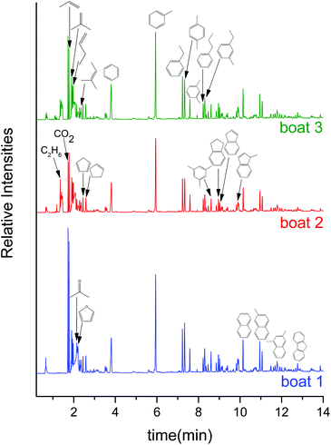
To gain further information regarding product distribution and overall mass balances attained with supported molybdenum oxide catalysts, the CFP of pine was investigated in a tandem micropyrolyzer–GCMS set up. The gas chromatograms after sequential pyrolysis of 3 boats loaded with ca. 0.5 mg of pine each over 40 mg of the MoO3/TiO2 catalyst show that the catalyst predominantly produces aromatic hydrocarbons, alkenes and alkanes (see Fig. 4). Specifically, benzene, toluene, ethylbenzene, xylenes, propylbenzene, 1-ethyl-3-methylbenzene, trimethylbenzenes, indane, indene, naphthalene, methylnaphthalenes, dimethylnaphthalenes, propene, 2-methylpropene, butene, 2-methyl-2-butene and ethane were identified. Other than a very small amount of acetaldehyde, acetone, butanone and furan, no other oxygenates were detected (see Table S1† for the full list of products). This product distribution remains relatively constant across the 3 boats, which corresponds to a total biomass![[thin space (1/6-em)]](https://www.rsc.org/images/entities/char_2009.gif) :
:![[thin space (1/6-em)]](https://www.rsc.org/images/entities/char_2009.gif) MoO3 mass ratio of 0.375. These GCMS data are in close agreement with the MBMS data (Fig. 1(d)), indicating that when the catalyst is still fresh, it is able to fully deoxygenate the primary pyrolysis vapours to form mostly aromatic hydrocarbons and alkenes under the reported reaction conditions. In contrast to the MBMS analysis, the GCMS-based analysis helps in distinguishing structural isomers. For example, the peak at m/z 120 in MBMS can be separated in the GCMS into methylethylbenzene, trimethylbenzene and propylbenzene. We note that, akin to the MoO3/TiO2, the MoO3/ZrO2 catalyst (Fig. S3†) displayed a similar hydrocarbon product distribution across the 3 pine boats (see Table S2† for the full list of products). Similar to the MBMS experiments, control experiments with bare supports showed no appreciable HDO activity (see Fig. S4 and S5†).
MoO3 mass ratio of 0.375. These GCMS data are in close agreement with the MBMS data (Fig. 1(d)), indicating that when the catalyst is still fresh, it is able to fully deoxygenate the primary pyrolysis vapours to form mostly aromatic hydrocarbons and alkenes under the reported reaction conditions. In contrast to the MBMS analysis, the GCMS-based analysis helps in distinguishing structural isomers. For example, the peak at m/z 120 in MBMS can be separated in the GCMS into methylethylbenzene, trimethylbenzene and propylbenzene. We note that, akin to the MoO3/TiO2, the MoO3/ZrO2 catalyst (Fig. S3†) displayed a similar hydrocarbon product distribution across the 3 pine boats (see Table S2† for the full list of products). Similar to the MBMS experiments, control experiments with bare supports showed no appreciable HDO activity (see Fig. S4 and S5†).
Bulk MoO3 was investigated for CFP of pine in the same set up. Although no products were observed after the first pine boat (see Fig. S6†), the same aromatic hydrocarbon products as those obtained with the supported MoO3 catalysts were observed after the pyrolysis of the 2nd pine boat. These peaks increased in intensity as more pine boats were introduced up to a total of 4 boats. Taken together, these data suggest bulk MoO3 undergoes an induction period similar to that previously reported during the CFP of cellulose33 and HDO of bio-oil model compounds.26 Therefore, the difference in reactivity data from the MBMS and GCMS instruments for bulk and supported MoO3 catalysts could be rationalised by the favourable metal-support interaction for the latter. Indeed, Shetty et al. demonstrated that TiO2 and ZrO2 accelerate the generation and stabilisation of intermediate Mo oxidation states, which appear to promote reactivity during the HDO of m-cresol.27
We note that the reactivity and catalytic performance data cannot be compared quantitatively between the MBMS and the micropyrolyzer–GCMS reactor configurations, given that the reaction conditions are drastically different in both set ups. For example, the hydrogen flow rate to catalyst mass is about 18 times higher in the micropyrolyzer–GCMS system than in the horizontal reactor MBMS system. Also, although the feed is introduced in a pulse-like fashion in both systems, the frequency of these events is much lower in the micropyrolyzer–GCMS (every 30 min) compared to that used for the MBMS (every 2 min). Thus, the catalysts are exposed to greater amounts of hydrogen over a longer duration before a subsequent pulse of biomass is introduced in the micropyrolyzer–GCMS system than in the horizontal reactor–MBMS configuration. Indeed, while hydrogen is crucial for retaining HDO activity in bulk MoO3, it can also change the speciation of active species on the catalyst surface by over-reduction.25 Despite these differences, both instruments generate data showing that MoO3/TiO2 and MoO3/ZrO2 are clearly better catalysts for CFP of pine than bulk MoO3, since they are active under both reactor conditions using only a tenth of the equivalent mass of bulk MoO3. The reactivity data also suggest that the supported MoO3 catalysts are active over a wider operating window than bulk MoO3 under the reaction conditions investigated here.
3.3 Quantification of products
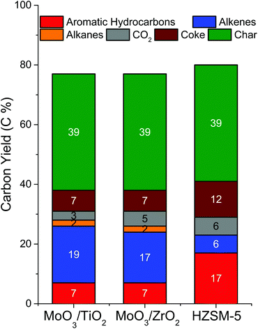
Most of the products were identified with MS and quantified using FID while CO2 was quantified using TCD. Average product yields were obtained by pyrolysing 3 pine boats over each supported catalyst (Fig. 5). Overall, both catalysts showed similar product distributions of ca. 7 C% aromatic hydrocarbons, 17–19 C% alkenes, 2 C% alkanes, 3–5 C% CO2, 7 C% coke and 39 C% char. Comparing the two supported catalysts, we note that both are equally effective for the CFP of pine as they produce equal amounts of most products, except for the slight difference (ca. 2%) observed in the amounts of alkenes and CO2 produced. Among the aromatic hydrocarbons, benzene and toluene are produced in similar yields and account for a total of 56–60% of the total aromatic hydrocarbon yield over both catalysts. The remaining aromatics include xylenes (10–11%), multisubstituted benzenes (14–16%), naphthalenes (9–10%) and indanes/indenes (4–7%). Butane and ethane comprise the majority of the alkanes (67–80%), while propene is the predominant alkene (62–69%). The remaining alkenes are butene (14%), methylbutene (4–5%), methylpropene (5%), cyclopentadiene (2–4%), cyclopentene (3–4%), ethylene (2%) and pentene (2–3%). CO and CH4 are the other light gases. A detailed list of the identified products is shown in Table S3.† Coke yield was determined by CHNS analysis of several spent catalyst samples. The char content was measured by averaging the weight of pine remaining after pyrolysis across 10 boats. An independent elemental analysis of char revealed that it contained approximately 85% carbon. A very small fraction of oxygenates (<0.5 C%) was observed only for MoO3/TiO2, including acetone, acetaldehyde, butanone and furan. Overall, the carbon balance is in the range of 80%. The unaccounted carbon could have been either lost during condensation of the light gases in the liquid nitrogen trap or some of the coke could have been scavenged by a hydrogen flow between successive pulses of biomass. Assuming a 60% mass yield of pyrolysis vapours from pine pyrolysis13 (i.e., excluding char and light gases) and similar carbon composition as pine, the catalysts can be assessed for their effectiveness to perform HDO. Both supported MoO3 catalysts yield about 12 C% aromatic hydrocarbons, 31 C% alkenes, 4 C% alkanes, 6 C% CO2 and 12 C% coke based on the carbon content of the pyrolysis vapours. These values translate to >40 C% of upgraded products for supported Mo catalysts when char is excluded. Overall, both MoO3/TiO2 and MoO3/ZrO2 showed similar product distributions during CFP of pine. They produced ca. 30 C% hydrocarbon products, with the remaining carbon in the form of CO2, char and coke on the catalysts. Although the upgrading temperature used in this study is 100 °C higher than that used by Nolte et al. during the CFP of corn stover over bulk MoO3, the product distributions are similar.33 Importantly, in contrast to bulk MoO3, supported MoO3 catalysts are capable of working at high biomass![[thin space (1/6-em)]](https://www.rsc.org/images/entities/char_2009.gif) :
:![[thin space (1/6-em)]](https://www.rsc.org/images/entities/char_2009.gif) catalyst ratios without requiring a hydrogen pre-activation step.
catalyst ratios without requiring a hydrogen pre-activation step.
In order to assess the performance of the supported MoO3 catalysts with respect to state-of-the-art HZSM-5 catalysts, the zeolite was tested under identical CFP reaction conditions (Fig. 5). HZSM-5 yielded 17 C% aromatic hydrocarbons, 6 C% alkenes, 6 C% CO2, 12 C% coke and 39 C% char. Overall, HZSM-5 produced ca. 23 C% hydrocarbon products, comparable to the hydrocarbon yield from supported MoO3 catalysts (ca. 27 C%). A full list of products identified is shown in Table S3.† These results are comparable to those obtained by Thangalazhy-Gopakumar et al.38 and Wang et al.39 for the ex situ CFP of pinewood chips and hybrid poplar, respectively, over HZSM-5 in a micropyrolyzer set up under reaction conditions (Table S4†) similar to those used in this study. Although supported MoO3 catalysts produced less aromatic hydrocarbons than HZSM-5, the combined selectivities to BTX (67–70%) were higher than those obtained with HZSM-5 (51%) in this study. Furthermore, the supported MoO3 catalysts produced about 3 times more olefins than HZSM-5. These olefins are valuable as they can be further treated with aromatics to form more useful alkylated aromatic products. As expected, HZSM-5 also showed a higher propensity to coking (12 C%) than supported MoO3 catalysts (7 C%). Although the reaction conditions were kept identical across the supported MoO3 and HZSM-5 catalysts, the effective catalyst mass used was different (4 mg MoO3 in supported MoO3 catalysts vs. 24 mg HZSM-5 in HZSM-5/SiO2) to obtain comparable conversions. Taken together, these results indicate that supported MoO3 catalysts are indeed promising alternative CFP catalysts to zeolites as they can operate at high biomass![[thin space (1/6-em)]](https://www.rsc.org/images/entities/char_2009.gif) :
:![[thin space (1/6-em)]](https://www.rsc.org/images/entities/char_2009.gif) catalyst ratios and produce hydrocarbons under mild conditions with yields comparable to those obtained with state-of-the-art catalysts.
catalyst ratios and produce hydrocarbons under mild conditions with yields comparable to those obtained with state-of-the-art catalysts.
3.4 Post-reaction characterisation
The catalysts were characterised post-reaction to reconcile the differences in reactivity observed in both reactor setups. PXRD patterns of fresh and spent MoO3/TiO2, MoO3/ZrO2 and bulk MoO3 are shown in Fig. 6, S7,† and Fig. 7, respectively. Only MoO3/TiO2 and bulk MoO3 show appreciable changes in the PXRD patterns after the reaction. Fresh MoO3/TiO2 features mostly peaks corresponding to the support TiO2 but two additional peaks are observed at 2θ = 23.7° and 34.2° associated with crystalline MoO3 clusters. These diffractions disappear after the reaction in both reactors, similar to the PXRD diffractions observed after HDO of m-cresol.27 Although no diffractions associated with molybdenum oxycarbohydride (MoOxCyHz) are detected, their presence cannot be ruled out given that these species might be below the detection limit of the diffractometer.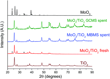 | ||
| Fig. 6 Normalised PXRD patterns of the fresh and spent MoO3/TiO2 catalysts in comparison with fresh TiO2 and MoO3 samples. The spent MoO3/TiO2 samples from both reactor systems were obtained at the end of the experiments shown in Fig. 3(a) and 4. | ||
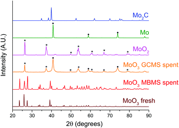 | ||
| Fig. 7 Normalised PXRD patterns of the spent bulk MoO3 catalysts in comparison with fresh MoO3, MoO2, Mo and Mo2C samples. The symbol (*) and (●) indicates the peak assignment corresponding to MoO2 and Mo respectively. The spent bulk MoO3 sample from micropyrolyzer–GCMS setup was retrieved after the experiment shown in Fig. S6.† | ||
The PXRD patterns for spent bulk MoO3 from the MBMS experiment feature peaks associated with fully oxidised MoO3. We note that MoO3 was not activated under H2 thus explaining the lack of catalytic activity (Fig. 7). In contrast, after the reaction in the micropyrolyzer–GCMS set up, only diffractions corresponding to MoO2 and metallic Mo are present. These results are consistent with the previously observed phase transformation of bulk MoO3 to a mixture of MoO2 and molybdenum oxycarbohydride (MoOxCyHz) during the HDO of m-cresol.26 However, since the temperature in this study is 180 °C higher than that used for the HDO of m-cresol, the full reduction of MoO3 to metallic Mo without the presence of oxycarbohydride or carbide peaks is expected.
XPS spectra were acquired to determine the oxidation states of the supported molybdenum oxide catalysts (Fig. 8). Pre-reaction spectra show only peaks associated with Mo6+ valence states, while after reaction, both catalysts show the presence of Mo5+ states, and, for MoO3/TiO2, a Mo3+ state as assigned by Choi et al.40 Both catalysts show that ca. 50% of Mo species on the surface exist in their intermediate oxidation states (Mo5+ and Mo3+). Such distribution of oxidation states on the supported catalysts is very similar to that observed for the same catalysts after the HDO of m-cresol.27 Taken together, these data suggest that the prevalence of Mo5+ and Mo3+ could lead to higher HDO activity and on-stream stability even after the catalyst observes a biomass![[thin space (1/6-em)]](https://www.rsc.org/images/entities/char_2009.gif) :
:![[thin space (1/6-em)]](https://www.rsc.org/images/entities/char_2009.gif) MoO3 ratio of 20. Since the reactivity data from the horizontal reactor–MBMS set up is not quantitative, a semi-quantitative approach was used to gain insight on the deactivation kinetics. The relative yields for hydrocarbons, furan/phenols and primary vapours PCs (Fig. 3) were normalized by their total sum to determine the fractional conversion of primary vapours to hydrocarbons/furans/phenols. The deactivation rates for both catalysts follow a first order deactivation model (see Fig. S8†). This deactivation behaviour is consistent with our observations from previous studies on the HDO of model compounds.25–27 A first order deactivation profile is strong evidence that coking is responsible for the observed loss in activity.41 However, we note that this analysis is semi-quantitative in nature and further studies are needed to obtain quantitative deactivation rates and to determine the exact nature of coke deposits on the catalyst surface.
MoO3 ratio of 20. Since the reactivity data from the horizontal reactor–MBMS set up is not quantitative, a semi-quantitative approach was used to gain insight on the deactivation kinetics. The relative yields for hydrocarbons, furan/phenols and primary vapours PCs (Fig. 3) were normalized by their total sum to determine the fractional conversion of primary vapours to hydrocarbons/furans/phenols. The deactivation rates for both catalysts follow a first order deactivation model (see Fig. S8†). This deactivation behaviour is consistent with our observations from previous studies on the HDO of model compounds.25–27 A first order deactivation profile is strong evidence that coking is responsible for the observed loss in activity.41 However, we note that this analysis is semi-quantitative in nature and further studies are needed to obtain quantitative deactivation rates and to determine the exact nature of coke deposits on the catalyst surface.
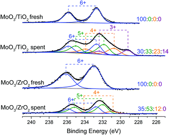 | ||
| Fig. 8 XPS spectra showing the Mo (3d) binding energy region of fresh and spent MoO3/TiO2 and MoO3/ZrO2 from the horizontal reactor–MBMS system. The spent catalysts were retrieved at the end of the experiments shown in Fig. 3. The ratios displayed correspond to the proportion of oxidation states Mo6+, Mo5+, Mo4+, and Mo3+ respectively. | ||
3.5 Potential industrial scale application
The current study was performed to show that supported MoO3 catalysts can serve as alternative upgrading catalysts to zeolites (e.g., HZSM-5) and that they can be indeed used for the CFP of lignocellulosic biomass. Although our direct comparison results (Fig. 5 and Table S3†) show that more favourable catalyst-to-biomass ratios can be achieved with these Mo-based catalysts when compared to zeolites, this ratio needs to be optimised further. The catalyst lifetime can be prolonged when it is operated in a FCC-like fluidized bed system where the vapour residence time is minimised to prevent secondary reactions, which can lead to excessive coking on the catalyst surface. Supported MoO3 catalysts can be regenerated by simple calcination in air.27 The FCC-like reactor system typically has a regenerator, which burns off the coke and regenerates the catalyst, which can then be recycled back into the ex situ CFP reactor.42,43 This mode of operation lowers the cost associated with purchasing a fresh catalyst. Moreover, supported MoO3 is also an economical catalyst that can be manufactured at scale. The current price for bulk MoO3 is ca. $0.02 per gram.44 We note that sulphided cobalt molybdenum (CoMo) and nickel molybdenum (NiMo) catalysts supported on Al2O3 are already being synthesised and used industrially in hydrodesulphurisation of petroleum fractions.42 These catalysts are initially synthesised in oxide forms, and presulphided to obtain sulphides prior to reaction.42 In contrast to zeolite catalysts, however, these supported MoO3 catalysts have not been formulated into attrition-resistant pellets compatible with FCC-like fluidized bed reactors.43 Further studies in this direction will be critical in optimising the catalyst performance before being used industrially. Process parameters45 such as temperature, biomass![[thin space (1/6-em)]](https://www.rsc.org/images/entities/char_2009.gif) :
:![[thin space (1/6-em)]](https://www.rsc.org/images/entities/char_2009.gif) catalyst ratio, biomass residence time, pyrolysis vapour residence time and catalyst regeneration conditions also need to be optimised prior to scale-up.43
catalyst ratio, biomass residence time, pyrolysis vapour residence time and catalyst regeneration conditions also need to be optimised prior to scale-up.43
4. Conclusions
Supported molybdenum oxide catalysts, MoO3/TiO2 and MoO3/ZrO2, are effective HDO catalysts capable of producing olefins and aromatic hydrocarbons from the CFP of pine. As the cumulative biomass to MoO3 mass ratio exposed to the catalytic bed increases, the catalysts become less effective for HDO, forming partially deoxygenated intermediates such as furans and phenols. Though the primary pyrolysis vapours break through at biomass![[thin space (1/6-em)]](https://www.rsc.org/images/entities/char_2009.gif) :
:![[thin space (1/6-em)]](https://www.rsc.org/images/entities/char_2009.gif) catalyst ratios ≥5, the catalysts remain active for HDO, as furans, toluene and phenols were observed even at a biomass
catalyst ratios ≥5, the catalysts remain active for HDO, as furans, toluene and phenols were observed even at a biomass![[thin space (1/6-em)]](https://www.rsc.org/images/entities/char_2009.gif) :
:![[thin space (1/6-em)]](https://www.rsc.org/images/entities/char_2009.gif) MoO3 ratio of 20. Both supported catalysts yielded about 30 C% hydrocarbon products, which are comparable yields to those obtained with HZSM-5 operated under similar reaction conditions. Supported MoO3 catalysts are more effective CFP catalysts than bulk MoO3. Post-reaction XPS analyses of the supported catalysts reveal that about half of the Mo surface species exist in their intermediate oxidation states (Mo3+ and Mo5+), which could explain the higher reactivity and stability as compared to bulk MoO3. Catalyst deactivation is likely associated to coking. Optimising the CFP reaction conditions as well as tuning the synthesis of the supported MoO3 catalysts are important parameters for improving HDO performance.
MoO3 ratio of 20. Both supported catalysts yielded about 30 C% hydrocarbon products, which are comparable yields to those obtained with HZSM-5 operated under similar reaction conditions. Supported MoO3 catalysts are more effective CFP catalysts than bulk MoO3. Post-reaction XPS analyses of the supported catalysts reveal that about half of the Mo surface species exist in their intermediate oxidation states (Mo3+ and Mo5+), which could explain the higher reactivity and stability as compared to bulk MoO3. Catalyst deactivation is likely associated to coking. Optimising the CFP reaction conditions as well as tuning the synthesis of the supported MoO3 catalysts are important parameters for improving HDO performance.
Acknowledgements
This research was funded by BP through the MIT Energy Initiative Advanced Conversion Research Program and the National Science Foundation (award number 1454299). Support for Budhi, Mukarakate and Nimlos was provided by the U.S. Department of Energy's Bioenergy Technologies Office (DOE-BETO) under contract no. DE-AC36-08GO28308 with the National Renewable Energy Laboratory. Calvin Mukarakate, Sridhar Budhi, and Mark Nimlos would like to thank Josiah McMillen and Kristina Iisa for their help with some of the CFP experiments.References
- H. S. Heo, H. J. Park, Y.-K. Park, C. Ryu, D. J. Suh, Y.-W. Suh, J.-H. Yim and S.-S. Kim, Bioresour. Technol., 2010, 101, S91–S96 CrossRef CAS PubMed.
- M. Asadullah, M. A. Rahman, M. M. Ali, M. A. Motin, M. B. Sultan, M. R. Alam and M. S. Rahman, Bioresour. Technol., 2008, 99, 44–50 CrossRef CAS PubMed.
- A. A. Boateng, D. E. Daugaard, N. M. Goldberg and K. B. Hicks, Ind. Eng. Chem. Res., 2007, 46, 1891–1897 CrossRef CAS.
- H. Wang, J. Male and Y. Wang, ACS Catal., 2013, 3, 1047–1070 CrossRef CAS.
- S. Czernik and A. Bridgwater, Energy Fuels, 2004, 18, 590–598 CrossRef CAS.
- G. Yildiz, M. Pronk, M. Djokic, K. M. van Geem, F. Ronsse, R. Van Duren and W. Prins, J. Anal. Appl. Pyrolysis, 2013, 103, 343–351 CrossRef CAS.
- D. A. Ruddy, J. A. Schaidle, J. R. Ferrell III, J. Wang, L. Moens and J. E. Hensley, Green Chem., 2014, 16, 454–490 RSC.
- C. Liu, H. Wang, A. M. Karim, J. Sun and Y. Wang, Chem. Soc. Rev., 2014, 43, 7594–7623 RSC.
- S. Wan and Y. Wang, Front. Chem. Sci. Eng., 2014, 8, 280–294 CrossRef CAS.
- H. Zhang, R. Xiao, H. Huang and G. Xiao, Bioresour. Technol., 2009, 100, 1428–1434 CrossRef CAS PubMed.
- A. Dutta, A. Sahir, E. Tan, D. Humbird, L. J. Snowden-Swan, P. Meyer, J. Ross, D. Sexton, R. Yap and J. Lukas, Process design and economics for the conversion of lignocellulosic biomass to hydrocarbon fuels. Thermochemical research pathways with in situ and ex situ upgrading of fast pyrolysis vapors, 2015.
- B. Li, L. Ou, Q. Dang, P. Meyer, S. Jones, R. Brown and M. Wright, Bioresour. Technol., 2015, 196, 49–56 CrossRef CAS PubMed.
- C. Mukarakate, X. Zhang, A. R. Stanton, D. J. Robichaud, P. N. Ciesielski, K. Malhotra, B. S. Donohoe, E. Gjersing, R. J. Evans, D. S. Heroux, R. Richards, K. Lisa and M. R. Nimlos, Green Chem., 2014, 16, 1444–1461 RSC.
- J. D. Adjaye and N. Bakhshi, Fuel Process. Technol., 1995, 45, 161–183 CrossRef CAS.
- J. Jae, G. A. Tompsett, A. J. Foster, K. D. Hammond, S. M. Auerbach, R. F. Lobo and G. W. Huber, J. Catal., 2011, 279, 257–268 CrossRef CAS.
- D. J. Mihalcik, C. A. Mullen and A. A. Boateng, J. Anal. Appl. Pyrolysis, 2011, 92, 224–232 CrossRef CAS.
- M. A. Jackson, D. L. Compton and A. A. Boateng, J. Anal. Appl. Pyrolysis, 2009, 85, 226–230 CrossRef CAS.
- C. Mukarakate, M. J. Watson, J. ten Dam, X. Baucherel, S. Budhi, M. M. Yung, H. Ben, K. Iisa, R. M. Baldwin and M. R. Nimlos, Green Chem., 2014, 16, 4891–4905 RSC.
- A. V. Bridgwater, Biomass Bioenergy, 2012, 38, 68–94 CrossRef CAS.
- H. Zhang, Y.-T. Cheng, T. P. Vispute, R. Xiao and G. W. Huber, Energy Environ. Sci., 2011, 4, 2297–2307 CAS.
- J. Scahill, J. Diebold and A. Porwer, in Research in Thermochemical Biomass Conversion, Springer, 1988, pp. 927–940 Search PubMed.
- T. R. Carlson, G. A. Tompsett, W. C. Conner and G. W. Huber, Top. Catal., 2009, 52, 241–252 CrossRef CAS.
- Y. T. Cheng, J. Jae, J. Shi, W. Fan and G. W. Huber, Angew. Chem., Int. Ed., 2012, 124, 1416–1419 CrossRef.
- P. A. Horne and P. T. Williams, J. Anal. Appl. Pyrolysis, 1995, 34, 65–85 CrossRef CAS.
- T. Prasomsri, T. Nimmanwudipong and Y. Román-Leshkov, Energy Environ. Sci., 2013, 6, 1732–1738 CAS.
- T. Prasomsri, M. Shetty, K. Murugappan and Y. Román-Leshkov, Energy Environ. Sci., 2014, 7, 2660–2669 CAS.
- M. Shetty, K. Murugappan, T. Prasomsri, W. H. Green and Y. Román-Leshkov, J. Catal., 2015, 331, 86–97 CrossRef CAS.
- W. S. Lee, Z. S. Wang, R. J. Wu and A. Bhan, J. Catal., 2014, 319, 44–53 CrossRef CAS.
- M. M. Sullivan and A. Bhan, ACS Catal., 2016, 6, 1145–1152 CrossRef CAS.
- W.-S. Lee, A. Kumar, Z. Wang and A. Bhan, ACS Catal., 2015, 5, 4104–4114 CrossRef CAS.
- M. M. Sullivan, J. T. Held and A. Bhan, J. Catal., 2015, 326, 82–91 CrossRef CAS.
- S. Budhi, C. Mukarakate, K. Iisa, S. Pylypenko, P. N. Ciesielski, M. M. Yung, B. S. Donohoe, R. Katahira, M. R. Nimlos and B. G. Trewyn, Green Chem., 2015, 17, 3035–3046 RSC.
- M. W. Nolte, J. Zhang and B. H. Shanks, Green Chem., 2016, 18, 134–138 RSC.
- D. Howe, T. Westover, D. Carpenter, D. Santosa, R. Emerson, S. Deutch, A. Starace, I. Kutnyakov and C. Lukins, Energy Fuels, 2015, 29, 3188–3197 CrossRef CAS.
- Y. Wang, S. Van de Vyver, K. K. Sharma and Y. Román-Leshkov, Green Chem., 2014, 16, 719–726 RSC.
- R. J. Evans and T. A. Milne, Energy Fuels, 1987, 1, 123–137 CrossRef CAS.
- M. W. Jarvis, T. J. Haas, B. S. Donohoe, J. W. Daily, K. R. Gaston, W. J. Frederick and M. R. Nimlos, Energy Fuels, 2010, 25, 324–336 CrossRef.
- S. Thangalazhy-Gopakumar, S. Adhikari, R. B. Gupta, M. Tu and S. Taylor, Bioresour. Technol., 2011, 102, 6742–6749 CrossRef CAS PubMed.
- K. Wang, P. A. Johnston and R. C. Brown, Bioresour. Technol., 2014, 173, 124–131 CrossRef CAS PubMed.
- J.-G. Choi and L. Thompson, Appl. Surf. Sci., 1996, 93, 143–149 CrossRef CAS.
- I. S. Nam and J. Kittrell, Ind. Eng. Chem. Process Des. Dev., 1984, 23, 237–242 CAS.
- J. H. Gary, G. E. Handwerk and M. J. Kaiser, Petroleum refining: technology and economics, CRC Press, 2007 Search PubMed.
- G. Yildiz, F. Ronsse, R. van Duren and W. Prins, Renewable Sustainable Energy Rev., 2016, 57, 1596–1610 CrossRef CAS.
- Molybdenum Prices and Molybdenum Price Charts, http://www.infomine.com/investment/metal-prices/molybdenum-oxide/.
- R. Venderbosch, ChemSusChem, 2015, 8, 1306–1316 CrossRef CAS PubMed.
Footnote |
| † Electronic supplementary information (ESI) available. See DOI: 10.1039/c6gc01189f |
| This journal is © The Royal Society of Chemistry 2016 |

