 Open Access Article
A free-standing LiFePO4–carbon paper hybrid cathode for flexible lithium-ion batteries†
Katja
Kretschmer
,
Bing
Sun
*,
Xiuqiang
Xie
,
Shuangqiang
Chen
and
Guoxiu
Wang
*
Centre for Clean Energy Technology, School of Mathematical and Physical Sciences, University of Technology Sydney, Sydney, NSW 2007, Australia. E-mail: Bing.sun@uts.edu.au; Guoxiu.Wang@uts.edu.au
First published on 5th January 2016
Abstract
Lithium-ion batteries (LIBs) are widely implemented to power portable electronic devices and are increasingly in demand for large-scale applications. One of the major obstacles for this technology is still the low cost-efficiency of its electrochemical active materials and production processes. In this work, we present a novel impregnation–carbothermal reduction method to generate a LiFePO4–carbon paper hybrid electrode, which doesn't require a metallic current collector, polymeric binder or conducting additives to function as a cathode material in a LIB system. A shell of LiFePO4 crystals was grown in situ on carbon fibres during the carbonization of microcrystalline cellulose. The LiFePO4–carbon paper electrode achieved an initial reversible areal capacity of 197 μA h cm−2 increasing to 222 μA h cm−2 after 500 cycles at a current density of 0.1 mA cm−2. The hybrid electrode also demonstrated a superior cycling performance for up to 1000 cycles. The free-standing electrode could be potentially applied for flexible lithium-ion batteries.
Introduction
Lithium-ion batteries (LIBs) are the primary power source for portable electronic devices, such as mobile phones and laptops, and are now also considered for large-scale applications, such as electric vehicles and renewable energy storage. The constantly increasing demand for LIBs requires not only more cost-efficient materials and production processes but also ecological battery components in order to build a sustainable industry that eventually leads us into a renewable energy future.1,2A typical LIB consists of a graphite based anode, a LiCoO2 cathode and a separator saturated with a liquid organic electrolyte. Both active materials, graphite and LiCoO2, are pasted onto a metal substrate or current collector (copper and aluminium), which requires the usage of polymeric binders and appropriate organic solvents.2,3 One approach to reduce the drawbacks of current LIBs could be the replacement of LiCoO2, an expensive and toxic layered metal oxide, which has been the most commonly used cathode material since LIBs were commercialized by Sony in 1990.2–4 Olivine type lithium iron phosphate (LiFePO4) is regarded as a suitable substitute for LiCoO2 due to its low cost, non-toxicity, high theoretical capacity (170 mA h g−1) and good cycling performance.5–10 The second improvement opportunity can be found in the replacement of the metal current collector, in case of the cathode side aluminium, with a low-cost, metal-free conductor.11,12 Recently, paper and textiles have been re-discovered as cheap, renewable and abundant materials for energy devices, such as supercapacitors, LIBs and Li–S (lithium–sulphur) batteries, which is mainly due to their intrinsic high surface area and porosity.13–21 For instance, Hu et al.22 developed a lithium-ion textile battery based on carbon nanotube (CNT) coated polyester, which was soaked with a slurry containing commercial Li4Ti5O12 (LTO) or LiFePO4 (LFP), polyvinylidene fluoride (PVDF) binder, conducting additives and N-methyl-2-pyrrolidone (NMP) as the solvent. Zhang et al.23 used commercially available rice paper laminated with a pre-sintered LFP precursor, PVDF and NMP slurry. The dried LFP precursor and rice paper intermediate was co-sintered to generate well-crystalized LFP and to in situ carbonize the rice paper substrate into a carbon fibrous film. Furthermore, the bare rice paper was used as a separator and served as an anode in a full battery design. These methods effectively substituted both metallic current collectors and stable full batteries could be assembled. Other reports also managed the polymeric binder PVDF by replacing the binder components with cellulose,24–26 so-called bundles of carbon nanostructures27 (highly entangled CNTs deposited onto a fibre surface via chemical vapour deposition) and even the use of electrostatic interactions28 has been reported, which resulted in good cycling performance and stability.
Taking all these innovative concepts into account, we designed a unique preparation method to generate a free-standing, binder-free and metallic current collector-free LFP cathode. In this report, we demonstrate the simultaneous carbonization of microcrystalline cellulose and the in situ crystal growth of LiFePO4 nanoparticles achieved by a novel impregnation–carbothermal reduction technique to create an innovative LiFePO4–carbon paper (LiFePO4@CP) hybrid electrode. No polymeric binders or conducting additives were used in this preparation process. The hybrid LiFePO4@CP electrode consists of a carbon fibre network core, which allows fast electron transport and provides a porous structure for electrolyte penetration. The thin LiFePO4 shell enables fast ion diffusion over a large surface area. This free-standing LiFePO4@CP hybrid electrode achieved a reversible capacity of 222 μA h cm−2, exceptional cycle life over 1000 cycles and high rate capabilities.
Experimental
Preparation of LiFePO4@CP cathodes
LiFePO4@CP was prepared by a novel 2-step impregnation–carbothermal reduction technique. A commercial paper towel (PT) was used as carbon paper owing to its porous nature, structural integrity and light weight. The PT was purified by soaking in 20 ml deionized water (DI water) for 2 h. Subsequently, 4 ml concentrated hydrochloric acid was added to the solution and left for another 12 h. The purified PT was washed with DI water several times by vacuum filtration and dried overnight at 100 °C in a vacuum oven. The dried tissue was impregnated for 10 minutes to ensure thorough saturation with a solution containing 1.0 g NH4H2PO4 and 0.365 g LiOH·H2O in 5 ml DI water (solution 1). A small amount of concentrated hydrochloric acid was added to the solution to restrain Li3PO4 precipitation. The saturated PT was subjected to freeze-drying overnight to obtain a homogenous loading of phosphate and lithium precursors. The iron precursor was introduced in a similar procedure. The phosphate and lithium loaded PT was weighed and impregnated based on the stoichiometric amount of Fe in the compound with the exact volume of a solution containing 1 g Fe(III)Cl3 and 30 wt% glucose in 10 ml DI water (solution 2) and was subsequently freeze-dried overnight. The dried and pre-loaded PT was then transferred into a ceramic crucible and sintered at 312 °C for 2 h and 700 °C for 10 h under a H2/Ar atmosphere.Structural and physical characterization
Crystallographic measurements were conducted using a Siemens D5000 X-ray diffractometer with CuKα radiation between 10° and 80°. The morphological analyses of the as-prepared material were carried out by field-emission scanning electron microscopy (FE-SEM, Zeiss Supra 55VP). The elemental mapping was conducted on a Zeiss EVO MA 15 SEM equipped with EDX. The carbon fibre/LiFePO4 particle interface and the structure of the coated carbon layer were characterized by high-resolution transmission electron microscopy (TEM, FEI Tecnai T20). The carbonization process of PT to CP and the carbon content of the as-prepared LiFePO4@CP electrode were investigated using a TGA/DTA analyser (TA Instruments, SDT 2960 module, New Castle, DE, USA) at a heating rate of 5 °C min−1 under air or nitrogen flow from room temperature to 700 °C.Electrode preparation and test cell assembly
The as-prepared LiFePO4@CP electrodes were used directly as working electrodes without further modification. The active material (LiFePO4) mass load was 2.8 mg cm−2. Lithium metal discs were used as counter and reference electrodes. The electrolyte consists of 1 M LiPF6 in dimethyl carbonate (DMC)/diethyl carbonate (DEC)/ethyl carbonate (EC) (volume ratio DMC![[thin space (1/6-em)]](https://www.rsc.org/images/entities/char_2009.gif) :
:![[thin space (1/6-em)]](https://www.rsc.org/images/entities/char_2009.gif) DEC
DEC![[thin space (1/6-em)]](https://www.rsc.org/images/entities/char_2009.gif) :
:![[thin space (1/6-em)]](https://www.rsc.org/images/entities/char_2009.gif) EC = 1
EC = 1![[thin space (1/6-em)]](https://www.rsc.org/images/entities/char_2009.gif) :
:![[thin space (1/6-em)]](https://www.rsc.org/images/entities/char_2009.gif) 1
1![[thin space (1/6-em)]](https://www.rsc.org/images/entities/char_2009.gif) :
:![[thin space (1/6-em)]](https://www.rsc.org/images/entities/char_2009.gif) 1). Approximately 40 μl electrolyte was used for each coin cell. The amount of liquid electrolyte uptake is calculated using the following equation:
1). Approximately 40 μl electrolyte was used for each coin cell. The amount of liquid electrolyte uptake is calculated using the following equation:where η is the uptake of the liquid electrolyte, and Wo and Wt are the weight of the electrodes before and after absorption of the liquid electrolyte, respectively. The electrolyte uptake was calculated to be 200 wt%. All electrodes were stored and all standard CR2032 type coin cells were assembled in an argon-filled glovebox (UniLab, MBRAUN).
Electrochemical characterization
Galvanostatic charge–discharge and cycling performance tests were performed in the voltage range of 2.00–4.25 V at various current densities on a Neware battery tester at room temperature. The cyclic voltammograms (CV) were obtained at different scanning rates of 0.1–2.0 mV s−1 between 2.0–4.5 V and electrochemical impedance spectroscopy (EIS) measurements were conducted over a frequency range from 100 kHz to 0.01 Hz using a CHI 660C Electrochemistry Workstation.Results and discussion
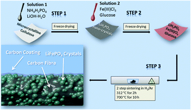
To prepare the free-standing LiFePO4@CP electrode (Fig. S1†) all three precursor components (lithium, iron and phosphate) are pre-loaded onto the microcrystalline cellulose fibre network via a solution-based impregnation and freeze-drying method, shown in Scheme 1.The XRD pattern of the purified cellulose, which is in agreement with previous reports,29,30 and the dried precursor solution (solution 1) can be found in the ESI (Fig. S2 and S3,† respectively). The subsequent heat treatment process is divided into two heating stages to firstly allow the degassing of the cellulose fibre at 312 °C for 2 h and secondly to grow LiFePO4 crystals on these newly generated carbon fibres at 700 °C for 10 h. The LiFePO4 shell itself consists of aggregates of LiFePO4 nano-crystals, which are densely packed on the carbon fibre surface. The close contact between the carbon fibre and the crystals is supported by a thin carbon coating generated from the reducing agent used for the carbothermal reduction reaction (Scheme 1). A detailed description of the preparation mechanism can be found in the ESI.†
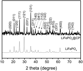
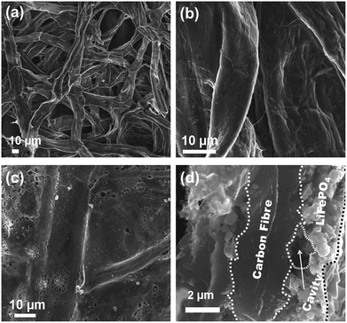
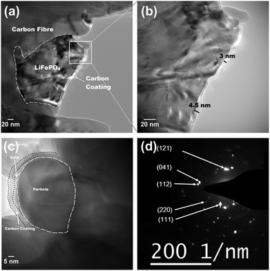
According to the XRD investigation (Fig. 1), no impurity phases have been generated during the high temperature treatment. This confirms the successful synthesis of LiFePO4 covering carbonized paper by the novel impregnation–carbothermal reduction technique. The obtained pattern can be consistently indexed to JCPDS card number 83-2092 of LiFePO4. As shown in the SEM images of Fig. 2(a) and (b), the generated carbon paper is an interwoven network of carbon fibres, which are completely covered by LiFePO4 particles. Fig. 2(c) shows the SEM image of the as-prepared LiFePO4@CP electrode wherein the individual intact carbon belts are distinguishable. The carbon fibre network is covered by a thin layer of LiFePO4 showing uninterrupted contact between the two surfaces, which is evident in Fig. 2(d) and the elemental mapping images in Fig. S4.† The inevitable shrinkage of the cellulose fibre during carbonization to carbon paper (Fig. S5†) seemingly does not result in a contact loss between the freshly generated LiFePO4 crystallites and the carbonizing paper surface. Consequently, it can be seen that the LiFePO4 layer was generated leaving random cavities behind (Fig. 2(d) and S7†), possibly caused by de-hydrogenation and de-oxygenation processes during the transition of the cellulose fibre to the fully-carbonized carbon paper.31 These cavities or pores are beneficial for electrolyte penetration, and thus, ion diffusion through the LiFePO4 layer.32 TEM imaging was conducted to visualize the cooperative combination of carbon fibre, LiFePO4 crystallite and carbon coating. Fig. 3(a) shows the TEM image of a single LiFePO4 crystal (dashed outlines) closely in contact with a piece of carbon fibre. The LiFePO4 crystals are covered by a thin layer of amorphous carbon (dotted outline) of about 3–5 nm thickness (Fig. 3(b)). This carbon layer continues on the carbon fibre surface, providing a conducting network between individual LiFePO4 particles and along the fibre surface. Furthermore, the carbon coating also formed a closed-packed yolk-shell structure with the LiFePO4 particles leaving small voids, which allows the material to contract during (dis)charge (Fig. 3(c)). The reinforcement provided by this thin carbon coating contributes to the cycling stability, which is usually determined by the added polymeric binder in a conventional electrode design due to swelling, decomposition or poor elasticity of some commonly-used products.33,34 In the case of our material, the carbon coating combines the function of a strong binder and a conducting additive without the disadvantages for cycle life and rate performance.35,36 And lastly, the selected area electron diffraction (SAED) pattern displayed in Fig. 3(d) exhibits a set of concentric rings with bright spots, which can be indexed as the olivine LiFePO4 phase in consistency with the XRD investigation shown in Fig. 1.
Thermogravimetric measurements displayed in Fig. S8† allow the determination of the nominal carbon content of the as-prepared LiFePO4@CP material. Heating pure LiFePO4 in air from room temperature to 700 °C results in a weight gain of 4.8%, slightly under the theoretical weight gain of 5.1% if Fe2+ is completely oxidized to Fe3+.37 The LiFePO4@CP electrode shows a weight loss of 68.9% up to 475 °C, followed by a slight weight gain plateauing at 72%. This result indicates a nominal carbon content of around 33 wt%, which is very reasonable assuming that the nominal carbon content substitutes the Al current collector (CP component), carbon black additives and polymeric binders (carbon coating component). The as-prepared LiFePO4@CP electrode can thus be directly used as the cathode in lithium-ion batteries without the Al current collector, conducting additives or binders.
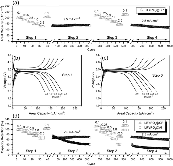
The evaluation of cycling stability and rate performance (Fig. 4(a)) was carried out using an unconventional approach, which incorporates both test conditions into one uninterrupted test sequence. This combined rate and stability performance test gives valuable insight on the durability of the as-prepared LiFePO4@CP electrodes under extremely stressful conditions of long-term fast cycling and relaxation during short-term slow cycling at various rates, respectively. Individually-tested electrodes were first cycled at different current rates from 0.1 to 2.5 mA cm−2 and back to 0.1 mA cm−2 in step one. Immediately after this rate performance test in step two, the cells were cycled at 2.5 mA cm−2 for 500 cycles to evaluate the cycling stability at high current rates. After that, the sequence was repeated once in step three and step four to identify performance changes of the cells. As shown in Fig. 4(a), step one was completed after 42 cycles. The LiFePO4@CP electrodes achieved reversible areal capacities of 197 μA h cm−2, 180 μA h cm−2, 163 μA h cm−2, 147 μA h cm−2, and 127 μA h cm−2 at current densities of 0.1, 0.25, 0.5, 1.0, and 2.5 mA cm−2, respectively. The capacity retention from 0.1 to 2.5 mA cm−2, displayed in Fig. 4(d), is as high as 65% and the cells recovered to 205 μA h cm−2 after the current density was reduced back to 0.1 mA cm−2. Immediately after the rate performance test, the same cells were cycled at 2.5 mA cm−2 for 500 cycles in step two and a progressive capacity increase can be observed as seen in Fig. 4(a). After this first cycling stability test, the LiFePO4@CP electrodes showed no sign of capacity fading. Instead, the electrode generated a capacity increase of about 5% to 134 μA h cm−2 (Fig. 4(a) and (c)). A progressive increase of reversible capacity can be observed. Similar activation phenomena have been reported previously for LiFePO4 particles incorporated into fibre matrices or conducting polymers, which also showed increasing capacities even over several 100 cycles.26,27,38 The reason for this might be found in the very dense packed distribution of particles forming the LiFePO4 shell. In this arrangement, the electrolyte penetration might not be completed throughout the entire electrode surface of the uncycled cell. The slight volume reduction during charging5 could open up new areas for the electrolyte, which enables the extraction of even more Li+ in the subsequent cycles until the electrolyte was able to penetrate the entire surface of the LiFePO4 shell. Furthermore, no capacity deterioration can be observed during the first rate and stability performance test sequence, which would indicate particle–particle and/or particle–CP contact loss. Both the particle collective as well as the particle–CP interface seem to remain intact even after over 500 deep (dis)charge cycles at high current densities. The second rate performance test in step three revealed reversible areal capacities of 222 μA h cm−2, 202 μA h cm−2, 186 μA h cm−2, 166 μA h cm−2, and 141 μA h cm−2 at current densities of 0.1, 0.25, 0.5, 1.0, and 2.5 mA cm−2, respectively, which translates into an average capacity increase of 10.5% compared to the initial rate performance in step one, as illustrated in Fig. 4(d). Moreover, the capacity retention from 0.1 to 2.5 mA cm−2 remained steady at 64% and the cells now recovered to 227 μA h cm−2 after the current density was decreased back to 0.1 mA cm−2. The subsequent second stability test in step four revealed a slight capacity decline starting after around 700 cycles. Consequently, the reversible capacity after 1000 cycles reaches a remarkable 115 μA h cm−2, which is 88% of the initial capacity measured during the first stability test in step two. Fig. 4(b) and (c) show the galvanostatic (dis)charge profiles of LiFePO4@CP cycled between 2.0 and 4.25 V at the current densities from 0.1 mA cm−2 to 2.5 mA cm−2 of step one and step three, respectively. It is evident that all profiles display the distinct charge–discharge behaviour of LiFePO4 showing two flat plateaus, one at around 3.5 V during charging and the other one at around 3.4 V during discharge. These two plateaus are associated with the Fe2+/Fe3+ redox couple reaction, which in detail refers to the oxidation of Fe2+ to Fe3+, and thus extracting Li+ during the charge process and vice versa the reduction of Fe3+ to Fe2+ and inserting Li+ during the discharge process.7,39,40
The corresponding differential capacity analyses are displayed in Fig. S9,† respectively. From there it can be seen that the voltage gaps between charge and discharge have significantly narrowed by an average of about 35% even for very high current densities, and the length of each plateau (Fig. 4(b) and (c)) has been increased in step three compared to step one. This result again indicates improved charge-transfer kinetics and increased Li+ utilization due to the progressive electrode activation process. For comparison, a similar test sequence was conducted using a traditional electrode (LiFePO4@Al) with the same active material mass load as the LiFePO4@CP electrodes (around 2.8 mg cm−2) containing a high performance LiFePO4 material, PVDF binder and carbon black (Fig. 4(d) and S10†). A detailed description of the preparation procedure of this LiFePO4 material is given in the ESI.† According to Fig. 4(d), the capacity retention from 0.1 to 2.5 mA cm−2 of around 70% for LiFePO4@Al is very similar to LiFePO4@CP in the first rate performance test of step one. As LiFePO4@Al entered the cycling stability test in step two at 2.5 mA cm−2 for 500 cycles, a dramatic capacity loss can be observed and only 54% of the initial capacity at the beginning of step two was maintained. At the end of step four after 1000 cycles LiFePO4@Al maintained 30% of its initial capacity at 2.5 mA cm−2 in step two. Furthermore, a second comparative test, as shown in Fig. S11,† was conducted to demonstrate capacity and stability in reference to the total weight of the electrode including the Al current collector, binder and additives, which strongly supports the proposed beneficial properties of a carbon paper based electrode design. Not only is the reversible capacity at a current density of 0.1 mA cm−2 of the LiFePO4@Al electrode (28 mA h g−1) significantly reduced compared to our LiFePO4@CP electrode (45 mA h g−1), the cycling stability also shows much more obvious decline over the tested 1000 cycles. This further demonstrates the superiority of the LiFePO4@CP electrode over the disadvantages of traditional electrode designs containing metal current collectors, polymeric binders and conducting additives. For the sake of completeness, however, the rate performance and cycling stability results are also converted into active material weight-specific capacity shown in Fig. S12.†
Fig. 5(a) unveils the cyclic voltametric (CV) behaviour of LiFePO4@CP at various scanning rates from 0.1 mV s−1 to 2.0 mV s−1 in the voltage range between 2.0 and 4.5 V after the electrode activation process (step two) was completed. A single pair of defined redox peaks can be observed for all scan rates, which corresponds to the Fe3+/Fe2+ redox couple as mentioned before. Furthermore, height and area of the redox peaks rise with increased scanning rates, as well as the anodic and cathodic peaks move to the lower and higher potentials, respectively. Even at a high scanning rate of 2.0 mV s−1, the defined redox reaction peaks are still maintained, indicating good kinetics for lithium intercalation and de-intercalation. According to the measured peak currents, a Li-ion diffusion coefficient D (cm2 s−1) can be calculated using the Randles–Sevcik equation:41–43
 | (1) |
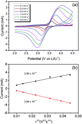 | ||
| Fig. 5 (a) CV profiles at different scan rates in the voltage range of 2.0 to 4.5 V and (b) peak current IPversus square root of scan rate ν0.5 at room temperature of LiFePO4@CP after 500 cycles. | ||
The Nyquist plot displayed in Fig. 6(a) compares the electrochemical impedance of LiFePO4@CP fresh and cycled for 500 cycles. It can be seen that the material generates a depressed semicircle in the high frequency region and a slope in the low frequency region. Firstly, the high frequency intercept of the semicircle with the real axis (Z′) refers to the uncompensated resistance (Ru), which combines the particle–particle contact resistance, electrolyte resistance and the electrode-current collector resistance. Secondly, the semicircle diameter refers to the charge transfer resistance (RCT), which is related to the electrochemical reactions at the electrode–electrolyte interface and the particle–particle contact. Lastly, the low frequency slope corresponds to the lithium-ion diffusion in the bulk of the electrode material and can be mathematically transformed to the Warburg coefficient (σw).
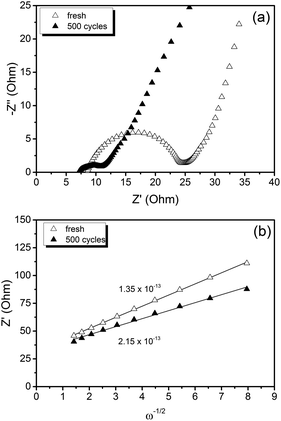 | ||
| Fig. 6 (a) Electrochemical impedance spectra and (b) linear fit of the Warburg impedance of a LiFePO4@CP cell fresh and cycled for 500 cycles. | ||
Consequently, the solid state diffusion of lithium-ions DLi through the LiFePO4 particle collective can be estimated using the following equation.43,45–48
 | (2) |
Overall, the measured charge transfer resistances are very low indicating excellent ionic and electronic transport along the electrode–electrolyte interface and strong particle–particle contact even after 500 high-rate deep (dis)charge cycles. Additionally, the solid state diffusion DLi calculated using eqn (2) from the Warburg impedance (shown in Fig. 6(b)) reflects the kinetic properties of the electrode, revealing a competitive lithium-ion diffusion rate of 1.35 × 10⁻¹³ cm2 s−1 for the fresh and 2.15 × 10⁻¹³ cm2 s−1 for the cycled cell measured from fully-lithiated LiFePO4, respectively. Here again, a kinetic improvement is observed upon cycling due to the cell activation process.
Conclusions
In conclusion, a novel free-standing LiFePO4@CP hybrid electrode has been developed, in which a shell of LiFePO4 crystallites on interwoven carbon fibres is embedded in a conductive carbon network. In this novel architecture, the carbon fibre fabric serves as the current collector, whilst the carbon coating provides conducting pathways and structural support for the LiFePO4 particle collective. This novel electrode design not only ensures close interparticle contact, but also high electronic conductivity for both mass and charge transfer. The LiFePO4@CP hybrid electrode delivered high areal capacity and excellent cycling stability for 1000 cycles at a high current density. It has been shown that metallic current collectors, polymeric binders and conducting additives can easily be substituted using commercial cellulose fibres and sugar, to generate a high performance LiFePO4@CP hybrid electrode, which could be used as the cathode in flexible lithium-ion batteries.Acknowledgements
This original research was proudly supported by Commonwealth of Australia through the Automotive Australia 2020 Cooperative Research Centre (AutoCRC).References
- X. Zeng, J. Li and N. Singh, Crit. Rev. Environ. Sci. Technol., 2014, 44, 1129–1165 CrossRef CAS.
- B. Scrosati, J. Hassoun and Y.-K. Sun, Energy Environ. Sci., 2011, 4, 3287–3295 CAS.
- M. Yoshio, R. J. Brodd and A. Kozawa, Lithium-Ion Batteries, Springer Science+Business Media, 2009 Search PubMed.
- T. Nagaura and K. Tozawa, Prog. Batteries Sol. Cells, 1990, 9, 209–217 CAS.
- A. K. Padhi, K. S. Nanjundaswamy and J. B. Goodenough, J. Electrochem. Soc., 1997, 1180–1194 Search PubMed.
- L.-X. Yuan, Z.-H. Wang, W.-X. Zhang, X.-L. Hu, J.-T. Chen, Y.-H. Huang and J. B. Goodenough, Energy Environ. Sci., 2011, 4, 269–284 CAS.
- S.-Y. Chung, J. T. Bloking and Y.-M. Chiang, Nat. Mater., 2002, 1, 123–128 CrossRef CAS PubMed.
- Y. Wang, P. He and H. Zhou, Energy Environ. Sci., 2011, 4, 805–817 CAS.
- J. Wang and X. Sun, Energy Environ. Sci., 2012, 5, 5163–5185 CAS.
- J. Zhang, L. Zhuo, L. Zhang, C. Wu, X. Zhang and L. Wang, J. Mater. Chem., 2011, 21, 6975–6980 RSC.
- N. Li, Z. Chen, W. Ren, F. Li and H.-M. Cheng, Proc. Natl. Acad. Sci. U. S. A., 2012, 109, 17360–17365 CrossRef CAS PubMed.
- Z. Cao and B. Wei, ACS Nano, 2014, 8, 3049–3059 CrossRef CAS PubMed.
- S. Leijonmarck, A. Cornell, G. Lindbergh and L. Wågberg, Nano Energy, 2013, 2, 794–800 CrossRef CAS.
- L. Hu and Y. Cui, Energy Environ. Sci., 2012, 5, 6423–6435 Search PubMed.
- http://data.worldbank.org/data-catalog/commodity-price-data , 2015.
- T. Song and B. Sun, ChemSusChem, 2013, 6, 408–410 CrossRef CAS PubMed.
- B. Dyatkin, V. Presser, M. Heon, M. R. Lukatskaya, M. Beidaghi and Y. Gogotsi, ChemSusChem, 2013, 6, 2269–2280 CrossRef CAS PubMed.
- H. Koga, H. Tonomura, M. Nogi, K. Suganuma and Y. Nishina, Green Chem., 2015 10.1039/C5GC01949D.
- L. Hu, N. Liu, M. Eskilsson, G. Zheng, J. McDonough, L. Wågberg and Y. Cui, Nano Energy, 2013, 2, 138–145 CrossRef CAS.
- J.-Q. Huang, H.-J. Peng, X.-Y. Liu, J.-Q. Nie, X.-B. Cheng, Q. Zhang and F. Wei, J. Mater. Chem. A, 2014, 2, 10869–10875 CAS.
- R. Berenguer, F. García-Mateos, R. Ruiz-Rosas, D. Cazorla-Amorós, E. Morallón, J. Rodríguez-Mirasol and T. Cordero, Green Chem., 2016 10.1039/C5GC02409A.
- L. Hu, F. L. Mantia, H. Wu, X. Xie, J. McDonough, M. Pasta and Y. Cui, Adv. Energy Mater., 2011, 1, 1012–1017 CrossRef CAS.
- L. C. Zhang, Z. Hu, L. Wang, F. Teng, Y. Yu and C. H. Chen, Electrochim. Acta, 2013, 89, 310–316 CrossRef CAS.
- L. Jabbour, C. Gerbaldi, D. Chaussy, E. Zeno, S. Bodoardo and D. Beneventi, J. Mater. Chem., 2010, 20, 7344–7347 RSC.
- L. Jabbour, M. Destro, C. Gerbaldi, D. Chaussy, N. Penazzi and D. Beneventi, J. Mater. Chem., 2012, 22, 3227–3233 RSC.
- L. Jabbour, M. Destro, D. Chaussy, C. Gerbaldi, N. Penazzi, S. Bodoardo and D. Beneventi, Cellulose, 2013, 20, 571–582 CrossRef CAS.
- B. S. Lalia, T. Shah and R. Hashaikeh, J. Power Sources, 2015, 278, 314–319 CrossRef CAS.
- X. l. Huang, R. z. Wang, D. Xu, Z. l. Wang, H. g. Wang, J. j. Xu, Z. Wu, Q. c. Liu, Y. Zhang and X. b. Zhang, Adv. Funct. Mater., 2013, 23, 4345–4353 CrossRef CAS.
- Q. Pang, L. Wang, H. Yang, L. Jia, X. Pan and C. Qiu, RSC Adv., 2014, 4, 41212–41218 RSC.
- X. Ju, M. Bowden, E. E. Brown and X. Zhang, Carbohydr. Polym., 2015, 123, 476–481 CrossRef CAS PubMed.
- X. Xie, K. Kretschmer, J. Zhang, B. Sun, D. Su and G. Wang, Nano Energy, 2015, 13, 208–217 CrossRef CAS.
- D. P. Singh, F. M. Mulder, A. M. Abdelkader and M. Wagemaker, Adv. Energy Mater., 2013, 3, 572–578 CrossRef CAS.
- S.-L. Chou, Y. Pan, J.-Z. Wang, H.-K. Liu and S.-X. Dou, Phys. Chem. Chem. Phys., 2014, 16, 20347–20359 RSC.
- Z. Zhang, T. Zeng, C. Qu, H. Lu, M. Jia, Y. Lai and J. Li, Electrochim. Acta, 2012, 80, 440–444 CrossRef CAS.
- K. Kirshenbaum, D. C. Bock, C.-Y. Lee, Z. Zhong, K. J. Takeuchi, A. C. Marschilok and E. S. Takeuchi, Science, 2015, 347, 149–154 CrossRef CAS PubMed.
- N. J. Dudney and J. Li, Science, 2015, 347, 131–132 CrossRef CAS PubMed.
- S. Yang, Y. Song, P. Y. Zavalij and M. S. Whittingham, Electrochem. Commun., 2002, 4, 239–244 CAS.
- J.-Z. Wang, S.-L. Chou, J. Chen, S.-Y. Chew, G.-X. Wang, K. Konstantinov, J. Wu, S.-X. Dou and H. K. Liu, Electrochem. Commun., 2008, 10, 1781–1784 CrossRef CAS.
- A. K. Padhi, K. S. Nanjunclaswamy, C. Masquelier, S. Okada and J. B. Goodenough, J. Electrochem. Soc., 1997, 5, 1609–1613 CrossRef.
- M. Thackeray, Nat. Mater., 2002, 1, 81–82 CrossRef CAS PubMed.
- Y. Xing, Y.-B. He, B. Li, X. Chu, H. Chen, J. Ma, H. Du and F. Kang, Electrochim. Acta, 2013, 109, 512–518 CrossRef CAS.
- X. Yang, F. Mou, L. Zhang, G. Peng, Z. Dai and Z. Wen, J. Power Sources, 2012, 204, 182–186 CrossRef CAS.
- W. L. Liu, J. P. Tu, Y. Q. Qiao, J. P. Zhou, S. J. Shi, X. L. Wang and C. D. Gu, J. Power Sources, 2011, 196, 7728–7735 CAS.
- N. Zhou, E. Uchaker, H.-Y. Wang, M. Zhang, S.-Q. Liu, Y.-N. Liu, X. Wu, G. Cao and H. Li, RSC Adv., 2013, 3, 19366–19374 RSC.
- J. Li, L. Zhang, L. Zhang, W. Hao, H. Wang, Q. Qu and H. Zheng, J. Power Sources, 2014, 249, 311–319 CrossRef CAS.
- R. Chen, Y. Wu and X. Y. Kong, J. Power Sources, 2014, 246–252 CrossRef CAS.
- Z. Ma, G. Shao, Y. Fan, G. Wang, J. Song and T. Liu, ACS Appl. Mater. Interfaces, 2014, 9236–9244 CAS.
- Z. Chen, M. Xu, B. Du, H. Zhu, T. Xie and W. Wang, J. Power Sources, 2014, 272, 837–844 CrossRef CAS.
Footnote |
| † Electronic supplementary information (ESI) available: XRD patterns, EDS mapping, TGA data, differential capacity analysis, additional cycling performance data, and digital photographs. See DOI: 10.1039/c5gc02602d |
| This journal is © The Royal Society of Chemistry 2016 |


