
 Open Access Article
 This Open Access Article is licensed under a
 Creative Commons Attribution 3.0 Unported Licence
Towards improved membrane production: using low-toxicity solvents for the preparation of PEEK nanofiltration membranes
João
da Silva Burgal
,
Ludmila
Peeva
and
Andrew
Livingston
*
Department of Chemical Engineering and Chemical Technology, Imperial College, Exhibition Road, London SW7 2AZ, UK. E-mail: a.livingston@imperial.ac.uk
First published on 16th December 2015
Abstract
In this work it is shown that PEEK membranes are “green” from the production point of view when compared with commercial polyimide (PI) based organic solvent nanofiltration (OSN) membranes. Green metrics (E-factor and solvent intensity) and waste cost were used in order to assess the environmental burden of PEEK membranes: the solvent intensity of PEEK membranes is 8.3 vs. 35–224 for PI based membranes, and the waste cost for PEEK membranes is 46 £ kg−1 of polymer vs. 1019 £ kg−1 of polymer (bench scale) and 189 £ kg−1 of polymer (industrial scale) for PI based membranes. Scaling-up of PEEK membranes to spiral-wound modules was successfully achieved with permeances between 0.26 L h−1 m−2 bar−1 and 0.47 L h−1 m−2 bar−1 for THF, and molecular weight cut-offs (MWCO) of ∼300 g mol−1. As a final assessment, the solvent intensity and environmental burden associated with permeating a THF flow of 100 L h−1 using PEEK membranes was also assessed. The results showed a waste cost of 1.4 £ m−2 of membrane, significantly lower than PI based membranes.
1 Introduction
Organic solvents are widely used in industry and pose a problem due to their high volatility, environmental persistence and high toxicity. Furthermore, these solvents will become waste solvent as they cannot be reused in the original process due to residual contaminations and quality and regulatory guidelines.1,2 Consequently, the demand for greener chemicals is increasing due to concerns from regulatory bodies when assessing environmental impacts, and to the tightening of discharge regulations.3 Following the 12 principles of green chemistry,4 membrane science could play an important role in the usage of safer solvents and auxiliaries, and in improving the energy efficiency of industrial processes. This is because membrane processes have low energy consumption, are simple to scale-up, operate and maintain.5–7Whilst membranes are green in terms of industrial processes, major environmental impact can be caused by their production and one cannot separate this from the industrial process application. Organic solvent nanofiltration (OSN) is emerging as a “green” separation technology in various industries, particularly as an alternative for pharmaceutical processes.8 Various publications evaluate the greenness of OSN processes, and compare it with conventional separations.5,7,9,10 However, very few publications consider the environmental impact of membrane production itself.6 Main focus is given to polymeric membranes as ceramic membranes require high temperature and pressures, limiting the improvement of these processes in terms of environmental burden.11 Nevertheless, in terms of bionanocomposites and/or hybrid materials there seems to be more flexibility to design “greener” routes.12,13
Nowadays, most integrally skinned asymmetric (ISA) OSN polymeric membranes are made from polymers such as polyimide (PI), polyacrylonitrile (PAN) and polyibenzimidazole (PBI). All of these polymers need to be dissolved in solvents such as N,N-dimethylformamide (DMF), N,N-dimethylacetamide (DMA), N-methyl-2-pyrrolidone (NMP), and tetrahydrofuran (THF).14–17 These solvents are considered harmful in GSK's Solvent Selection Guide for Medicinal Chemistry and industry has been trying to avoid them in order to implement safer processes.18,19 In addition to this, membranes prepared from the above polymers are only resistant in most polar aprotic solvents after chemical cross-linking of the polymer, and the membrane structure is only maintained through the addition of a preserving agent such as PEG or silicone oil. Polyimide (the most commonly used polymer for OSN membranes) is usually cross-linked with difunctional amines that might not react fully (usually they are present in excess), which will further create an environmental burden in terms of waste generation.20,21 Some “greener” alternatives for preparing PI OSN membranes have been proposed. For instance, Soroko et al.22 proposed a method where the original solvents are replaced by DMSO and acetone (which are considered “greener” solvents when compared to DMF and 1,4-dioxane), and the crosslinking step is performed using water as a solvent (instead of IPA). The authors reported that membranes prepared using this method have similar performance in terms of rejection compared to PI OSN membranes prepared from DMF/1,4-dioxane, with the advantage of eliminating toxic organic solvents in the membrane formation step. Another method for PI membrane preparation was proposed by Vanherck et al.23 and consists of simultaneous phase inversion and coagulation (SIM) of the polymer dope solution. In this method the cross-linker is dissolved in the coagulation bath (a 2 in 1 approach) at lower concentrations, 0.5% to 5% (w/v), thus generating less waste. This method was further developed in a research work by Hendrix et al. where three different difunctional amines were studied in concentrations ranging from 3% to 9% (w/v).24
Safer solvents like methyl and ethyl lactate,25,26 triethylphosphate (TEP),27 dimethyl sulfoxide (DMSO),22 γ-butyrolactone (γ-BL), and ionic liquids (ILs) have been proposed for replacing the “classic” solvents in the phase inversion technique.3 For example, Xing et al.28 presented a method of preparing PBI using the ionic liquid 1-ethyl-3-methylimidazolium acetate ([EMIM]OAc) as an alternative to DMAc as a solvent. Most of these solvents are used for dissolving polymers that are either not stable in organic solvents (such as cellulose acetate for example) or stable in a limited number of solvents like PBI or PI and require further chemical cross-linking in order to be resistant to harsh solvents (see Fig. 1).
 | ||
| Fig. 1 Schematic representation of the steps involved in the PI and PEEK membrane preparation. | ||
An alternative polymer that can be used in OSN is poly(ether ether ketone) (PEEK). This polymer exhibits strong chemical resistance in harsh solvents, and PEEK membranes require neither cross-linking due to their inherent chemical resistance, nor pore preserving agents.29 In addition, the solvents used to dissolve PEEK are methane sulphonic acid (MSA) and sulphuric acid (SA), which can be simply neutralized in water by adding a base. These membranes have been proven to operate in a continuous Heck catalytic reaction under harsh conditions (DMF, high temperature and high base concentration) throughout a period of 250 hours.30
In this paper, a comparison between the manufacturing process of OSN PEEK membranes and three ways of manufacturing PI based membranes (one of the widely used OSN ISA membranes on the market) was performed in terms of green metrics. The evaluation is implemented for both lab scale and postulated industrial scale production. In addition, scaling-up of PEEK membranes to spiral-wound modules was achieved and a comparison between PEEK modules and PI modules manufacturing was assessed in terms of environmental burden for permeating 100 L h−1 of THF.
2 Methods
2.1 Materials
2,4-Diphenyl-4-methyl-1-pentene (α-methylstyrene dimer) and methanesulphonic acid (MSA) were obtained from Sigma-Aldrich. Tetrahydrofuran (THF) and sulphuric acid (SA) 95 vol% was obtained from VWR UK. VESTAKEEP® 4000P was kindly obtained from Evonik Industries. The styrene oligomer standards with a molecular weight distribution of 580 (PS580) and 1300 (PS1300) were obtained from Agilent Technologies Deutschland GmbH, Germany. All reagents were used as received, without any further purification.2.2 Membrane preparation
PEEK powder VESTAKEEP® 4000P was dissolved at a concentration of 12 wt% in a mixture of 3![[thin space (1/6-em)]](https://www.rsc.org/images/entities/char_2009.gif) :1 wt% methanesulfonic acid (MSA) and sulphuric acid (SA) by mechanical stirring (IKA RW 20 digital) at 20 °C until complete homogenisation of polymer solution. Prior to casting, the polymer solution was left 72–96 hours at 20 °C until air bubbles were completely removed. All the membrane formation steps were performed in an air conditioned room at 20 °C and with a relative humidity (RH) in the range of 30–40%.
:1 wt% methanesulfonic acid (MSA) and sulphuric acid (SA) by mechanical stirring (IKA RW 20 digital) at 20 °C until complete homogenisation of polymer solution. Prior to casting, the polymer solution was left 72–96 hours at 20 °C until air bubbles were completely removed. All the membrane formation steps were performed in an air conditioned room at 20 °C and with a relative humidity (RH) in the range of 30–40%.
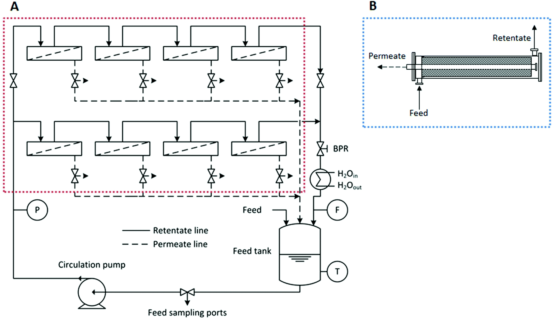 | ||
| Fig. 2 Schematic representation of the two configurations used in this study for testing membrane discs (configuration A) and membrane spiral wound modules (configuration B, flow diagram not depicted but similar to the one in configuration A). Legend: P – pressure gauge; T – thermocouple; F – flow meter; BPR – back pressure regulator. | ||
| Membrane code | Casting scale | Casting speed (m s−1) | Total length (m) |
|---|---|---|---|
| M1 | Bench | 0.005 | 0.3 |
| M2 | Continuous | 0.01 | 5 |
| M3 | Continuous | 0.06 | 5 |
2.3 Polystyrene markers solution and analysis
The polystyrene standard solution was prepared by dissolving 2,4-diphenyl-4-methyl-1-pentene (dimer, MW = 236 g mol−1) and Polystyrene Standards with a MW ranging from 295 to 1995 g mol−1 (homologous series of styrene oligomers (PS)) in a solvent at a concentration of 1 g L−1 each MW. Permeate and retentate samples were collected at different time intervals for rejection determination. Concentrations of PS in permeate and retentate samples were analysed using an Agilent HPLC system with a UV/Vis detector set at a wavelength of 264 nm. Separation was accomplished using an ACE 5-C18-300 column (Advanced Chromatography Technologies, ACT, UK). A mobile phase comprising 35 vol% analytical grade water and 65 vol% tetrahydrofuran (THF) both containing 0.1 vol% trifluoroacetic acid was used.162.4 Membrane performance
The flux (J) and permeance (LP) were determined using eqn (1) and (2) and the rejection (Ri) of PS was evaluated applying eqn (3). The corresponding MWCO curves were obtained from a plot of the rejection of PS versus their molecular weight. | (1) |
 | (2) |
 | (3) |
In order to test the membranes a rig with 8 cross-flow membrane cells (effective membrane area = 14 cm2 per cell) was used (see Fig. 2). A polystyrene standard solution was poured into the feed reservoir and the system was pressurized to 30 bar and the temperature set at 30 °C. In order to test the spiral-wound module the same system was used by simply disconnecting the 8 cross-flow cells from the whole system and connecting the module instead.
2.5 Atomic force microscopy (AFM)
Atomic force microscopy was carried out using Multimode 4 (Bruker, CA, USA) atomic force microscope (AFM) equipped with E-type or J-type piezo scanner. Samples were attached on a microscope glass slide using double sided tape. The images were captured under tapping mode using a silicon probe (PPP-NCH, Nanosensors™, Switzerland) having nominal tip radius of 7 nm with cantilever resonance frequency range of 204–497 kHz and spring constant of 42 N m−1. Scan size of 5 μm for standard images (analysis of roughness) was captured. A sampling resolution of 512 points per line and a speed of 1 Hz were used. Surface roughness is presented as average roughness (Ra) and root-mean-square roughness (Rrms).2.6 Scanning electron microscopy (SEM)
For cross-section imaging a membrane sample was broken in liquid nitrogen and pasted vertically onto SEM stubs covered with carbon tape. For surface imaging a membrane sample was cut and pasted horizontally onto SEM stubs covered with carbon tape. The samples were then coated with a chromium-layer in a Q150T turbo – pumped sputter coater (Quorum Technologies Ltd). SEM pictures of the surface and cross section of membrane samples were recorded using a high resolution SEM, LEO 1525, Karl Zeiss with an accelerating voltage of 5 kV and under dry conditions at room temperature.2.7 Experimental design
Each experiment was repeated in parallel using membrane coupons obtained from different locations on the membrane sheet. For the module data two continuous membrane sheets were produced from two different polymer dopes cast at different speeds (see section 2.2.2). Data are presented as means ± standard deviation of the mean (SDM).3 Results and discussion
3.1 Evaluating the “greenness” of PEEK membrane production
Green metrics for the production of PEEK membranes were calculated and compared with P84 polyimide (PI) membranes manufactured in three different ways. The first method considers P84 membranes produced by dissolving the polymer in DMF and 1,4-dioxane, carrying out phase inversion in water and crosslinking with diamine in IPA. This is a well-established procedure widely reported in literature.14,16 The other two methods introduce some modifications to the original procedure. The second method is P84 production using DMSO and acetone in place of DMF and 1,4-dioxane, and was proposed by Soroko et al.;22 the third method is P84 production through simultaneous phase inversion and cross-linking (SIM) and was reported by Hendrix et al.24For fairness of comparison the PEEK and P84 PI based membranes presented in this study have similar separation properties, i.e. molecular weight cut-offs (MWCOs) in the range of ∼300 g mol−1. The experimental procedures for the production of P84 PI membranes and PEEK membranes are summarized in Table 2.
| PEEK | P84 standard method | P84 green method | P84 SIM method | |
|---|---|---|---|---|
| a Please note that crosslinking in the standard method is performed in IPA (4.8 wt% crosslinker), the concentration is recalculated for the water bath to simplify the comparison with the other methods. | ||||
| Polymer (wt%) | 12% | 22% | 22% | 22% |
| Solvents (wt%) | MSA: 66% SA: 12% | DMF: 58.5% | DMSO: 58.5% | NMP: 44% |
| 1,4-Dioxane: 19.5% | Acetone: 19.5% | THF: 29% | ||
| IPA: 5% | ||||
| Phase inversion in water | Yes | Yes | Yes | Yes |
| Solvent exchange (e.g.: IPA) | No | Yes | No | No |
| Crosslinking | No | Yesa (0.1 w/v% of water bath) | Yes (0.1 w/v% of water bath) | Yes (3 w/v% of water bath) |
| Conditioning in PEG/IPA or IPA | No | Yes | Yes | Yes |
A comparison between bench and industrial scales was also performed for each of the membranes studied. For a bench scale membrane, usually 30 g of dope solution are cast onto a non-woven backing and immersed in a 20 L water bath (10 L of water for PEEK membranes). The membranes are then washed with 1.5 L water and subsequently P84 membranes are washed with IPA. For industrial scale the following assumption was made: 83.3 kg of polymer dope solution are cast on a non-woven backing material and immersed in a 10 m3 water bath (7 m3 of water for PEEK membranes). The membranes are then rinsed for 3 h in 0.5 m3 of water and P84 membranes are later washed with IPA. For P84 membranes there is also the chemical crosslinking step which generates liquid waste. Usually a 40 wt% excess of diamine (e.g. 1,6-hexamethylenediamine, HDA) is dissolved in a solvent (0.8 kg HDA kg−1 of dope and 7 kg of crosslinking medium per 1 kg of dope). The density for PEEK and P84 membrane films is 212 kg m−3 and 464 kg m−3 respectively and the thickness of the membrane films is 140 μm (values obtained experimentally). In this study, and for reasons of simplicity, it was considered that the solvents, crosslinking reagent, IPA and PEG were disposed with the water bath (see Fig. 3). All solvents and reagents except acetone and IPA have high boiling points and cannot easily be removed from water by evaporation. In addition to this, the levels of organic solvents present in waste water are very high (see Fig. 4C) and they need to be further treated in order to reduce toxicity levels. Note that DMSO and acetone are less toxic when compared with DMF and 1,4-dioxane, but they still need to be removed from the waste water before disposal in order to comply with environmental regulations. The price for disposing liquid waste is £7.50 per 25 L of chlorinated or non-chlorinated solvent.6 Although PEEK does not generate organic solvent waste it does generate an acidic (pH < 1) waste, water rich in sulphates and sulphites that has to be neutralized with a solution of NaOH (price 12.12 £ kg−1, VWR). In this study the amount of NaOH (solution of 0.5 M) necessary to fully neutralize the H+ ions present in the waste water was taken into account for calculating the waste cost; this acid–base reaction leads to the formation of sodium sulphate and sodium sulphite in solution.
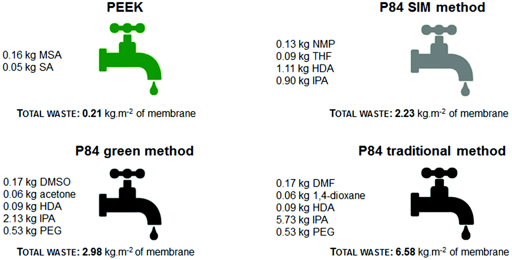 | ||
| Fig. 3 Comparison of the composition of the waste stream and the total waste generated per m2 of membrane at industrial scale. | ||
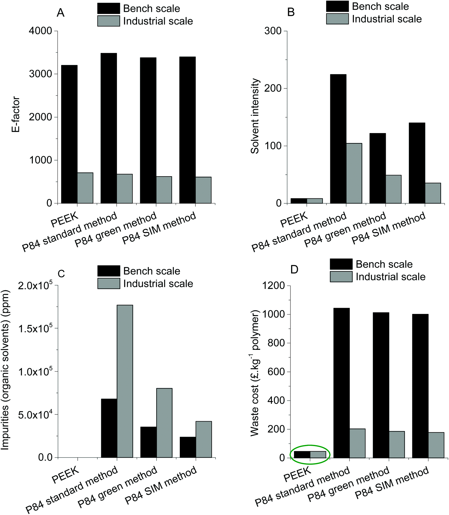 | ||
| Fig. 4 E-factor, solvent intensity, organic solvent impurities in aqueous waste stream and waste cost treatment for PEEK membranes and P84 membranes produced in bench and industrial scale. | ||
It is important to point out that solvent waste is a complex subject and should be incorporated when designing an environmentally friendly process.31 For example, Amelio et al.2 compared incineration of waste solvents with distillation using Eco-indicator 99, UBP-97, global warming potential, cumulative energy demand and CO2-balance. These metrics can be used when performing a lifecycle assessment which is not the aim of our research paper. In this study, the green metrics used, E-factor and solvent intensity, are presented below (eqn (4) and (5)). These metrics were chosen to be comparable with previously reported results.6
 | (4) |
 | (5) |
The E-factor (Fig. 4A) for all membranes is lower when producing at industrial scale than at bench scale because per kg of polymer less water is used at industrial scale. Nevertheless, the E-factor is very similar for all membranes at the respective scale which is a result of the high usage of water for phase inversion. Analyzing the solvent intensity (Fig. 4B) it can also be seen that the industrial scale is more efficient and less IPA is consumed. For both scales (bench and industrial) producing P84 membranes using the standard method has the highest solvent intensity, followed by the green method and SIM method (the P84 production method that consumes the least solvents of the three at industrial scale). PEEK membranes have the lowest solvent intensity with a value of 8.3 (for both scales) due to the usage of only MSA and SA as solvents throughout the whole production process. This is the reason why there are no organic solvents present in the waste water stream originating from the production of PEEK membranes (Fig. 4C). Production of P84 via the standard method generates the highest concentration of organic solvents at both industrial (∼1.8 × 10⁵ ppm) and bench scale (∼6.8 × 10⁴ ppm) due to the usage of high boiling point solvents in the dope preparation and the usage of IPA for cross-linking and/or conditioning. The other two methods of producing P84 generate lower amounts of impurities in the waste stream but are still in the order of magnitude of 104 to 105 ppm.
The fact that no organic solvent waste is generated during PEEK production makes the waste cost treatment at industrial scale 4.1 times lower (in average) when compared with the P84 industrial scale production methods, and 22.2 times lower (in average) at bench scale.
3.2 Scaling-up PEEK membranes to spiral-wound membrane modules
A proof of concept for scaling up PEEK membranes to spiral-wound module was performed in this work. The first step was to assess the stability and performance of PEEK membranes produced at bench and continuous scales and then subjected to drying at 20 °C and 70 °C (see Table 3 for a summary of membranes prepared). The membranes were tested in the 8-cell rig (membrane discs with an area of 14 cm2) using THF as solvent and PS as solute markers. The membranes produced at bench scale had similar performances (20 °C drying, M1.1 and 70 °C drying, M1.2): MWCO of ∼395 g mol−1 and permeance of ∼0.20 L h−1 m−2 bar−1 (Fig. 5 left). This can be explained by their similar average separating layer thickness of ∼180 nm (see Fig. 6).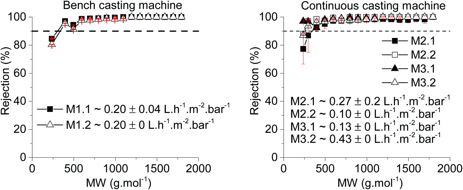 | ||
| Fig. 5 Left: rejection values and permeance of PEEK membranes cast using bench casting machine and dried at 20 °C (M1.1) and at 70 °C (M1.2) as a function of the molecular weight (MW, g mol−1) of different polystyrenes over time. Right: rejection values and permeance of PEEK membranes cast continuous and dried at 20 °C (M2.1 and M3.1) and at 70 °C (M2.2 and M3.2) as a function of the molecular weight (MW, g mol−1) of different polystyrenes over time. The membranes were tested in the 8 cross-flow cells with a solution of THF and PS (1 g L−1) for 24 hours. | ||
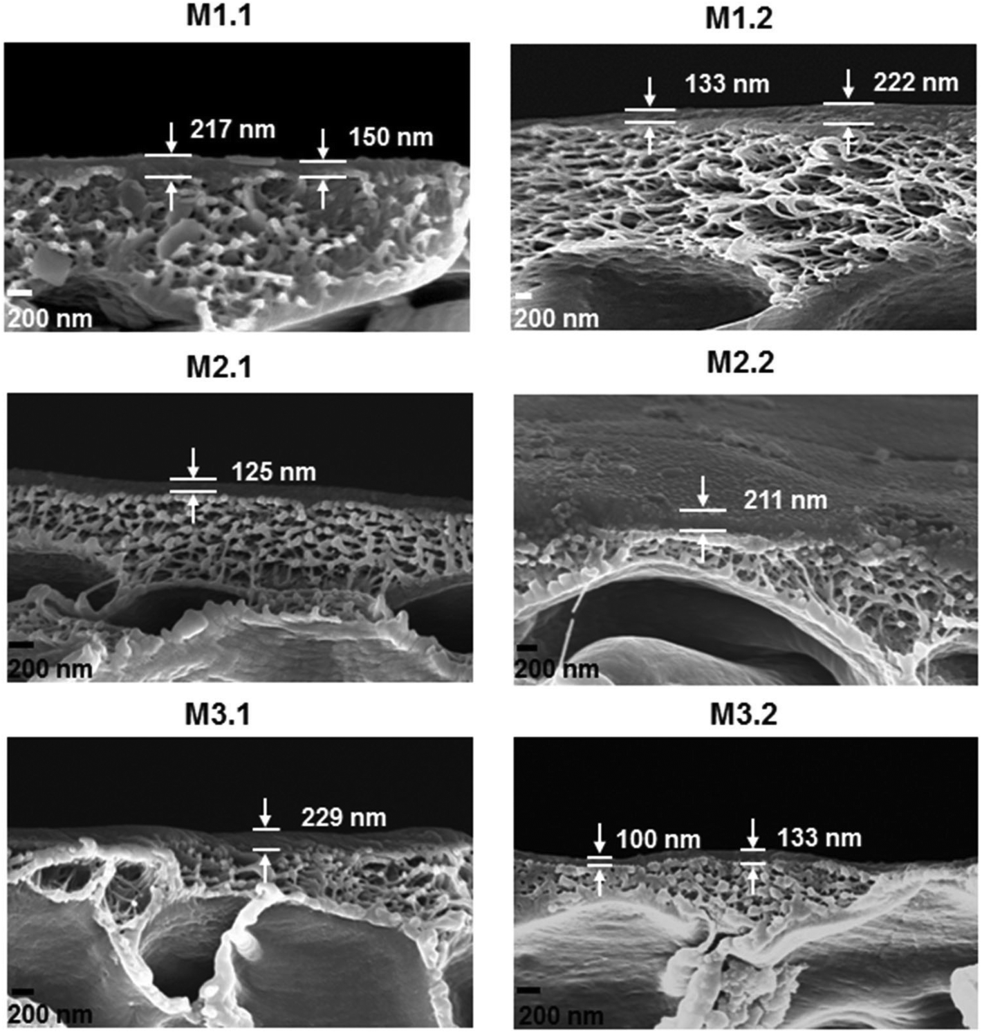 | ||
| Fig. 6 SEM cross-sectional images of membranes M1.1, M1.2, M2.1, M2.2, M3.1 and M3.2. | ||
| Membrane code | Membrane batch | Casting scale | Drying temperature (°C) |
|---|---|---|---|
| M1.1 | M1 | Bench | 20 |
| M1.2 | M1 | Bench | 70 |
| M2.1 | M2 | Continuous | 20 |
| M2.2 | M2 | Continuous | 70 |
| M3.1 | M3 | Continuous | 20 |
| M3.2 | M3 | Continuous | 70 |
For the membranes produced continuously, M2 and M3, the rejection was similar irrespective of the drying temperature. The permeance difference between M2.1 and M2.2 was +0.17 L h−1 m−2 bar−1 and the permeance difference between M3.1 and M3.2 was −0.30 L h−1 m−2 bar−1. Comparing the membranes from different batches but dried at the same temperature also showed a considerable difference (M2.1 vs. M3.1 and M2.2 vs. 3.2). These differences in permeance could be explained by the spatial variation of the membranes and indicates that a better controlled process may be required (Fig. 6). However, the average permeance of the four samples from continuous manufacture – M2.1, M2.2, M3.1 and M3.2 – is 0.235 L h−1 m−2 bar−1, which is close to the bench scale manufacture. The reason for using two different casting speeds in continuous manufacturing was to avoid the creases obtained in M2 (see Fig. 7D) attributed to the lower casting speed used for producing that membrane.
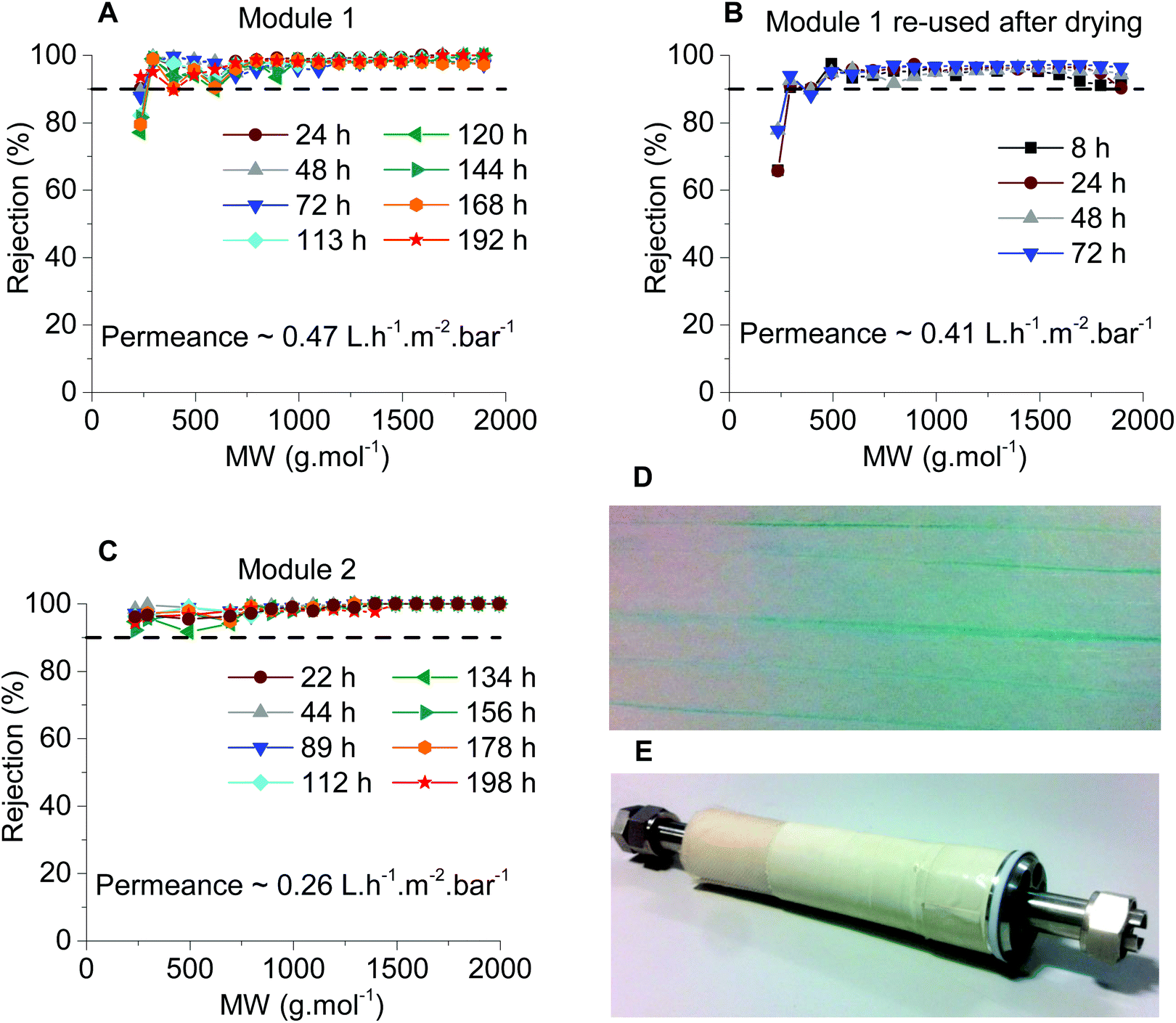 | ||
| Fig. 7 Rejection values and permeance of PEEK spiral wound module as a function of the molecular weight (MW, g mol−1) of different polystyrenes over time. The membranes were filtered with a solution of THF and PS (1 g L−1). (A) Filtration run performed over a period of 192 hours with Module 1 (membrane from M2 batch). (B) Filtration run performed over a period of 72 hours re-using Module 1 after drying it from THF. (C) Filtration run performed over a period of 198 hours with Module 2 (membrane from M3 batch). (D) Membrane surface of membrane from M2 batch depicting creases. E: Module 2. | ||
The modules tested, Modules 1 and 2, presented the same rejection values as the flat sheet membranes which were used to produce them, M2 and M3 respectively. However, the modules had different values of permeance when compared with the flat sheet membranes (Fig. 7). Module 1 had a permeance of 0.47 L h−1 m−2 bar−1 whereas M2.1 and M2.2 had permeances of 0.27 and 0.1 L h−1 m−2 bar−1, respectively. Module 2 presented a permeance of 0.26 L h−1 m−2 bar−1 while M3.1 and M3.2 had permeances of 0.13 and 0.43 L h−1 m−2 bar−1, respectively. From the data obtained from the 8-cell rig for membrane discs, a non-uniformity of the separating layer across the 5 m length of the continuous membranes (M2 and M3) was hypothesized. These differences in thickness of the separating layer could explain the discrepancies in permeance. From the SEM images, on an average of 4 samples (separated by 30 cm in longitudinal direction, 3 measurements for each sample separated by 500 nm) thicker separating layers for Module 2 can be seen when compared with Module 1, 230 nm and 176 nm respectively (Fig. 8 and Table 4), thus explaining the higher permeance value for Module 1. In addition, some rather thin areas were observed in the separating layer of Module 1 as opposed to Module 2 where unusually thick areas were present (Fig. 8). It should be noted that the total area of membrane under test in a module (0.2 m2) is much higher than a disc (0.0014 m2), and so the module represents an integrated permeance over a much larger sample. Using AFM images it was possible to verify an increase in roughness from the flat sheet membranes (before filtration) to the modules (after filtration).
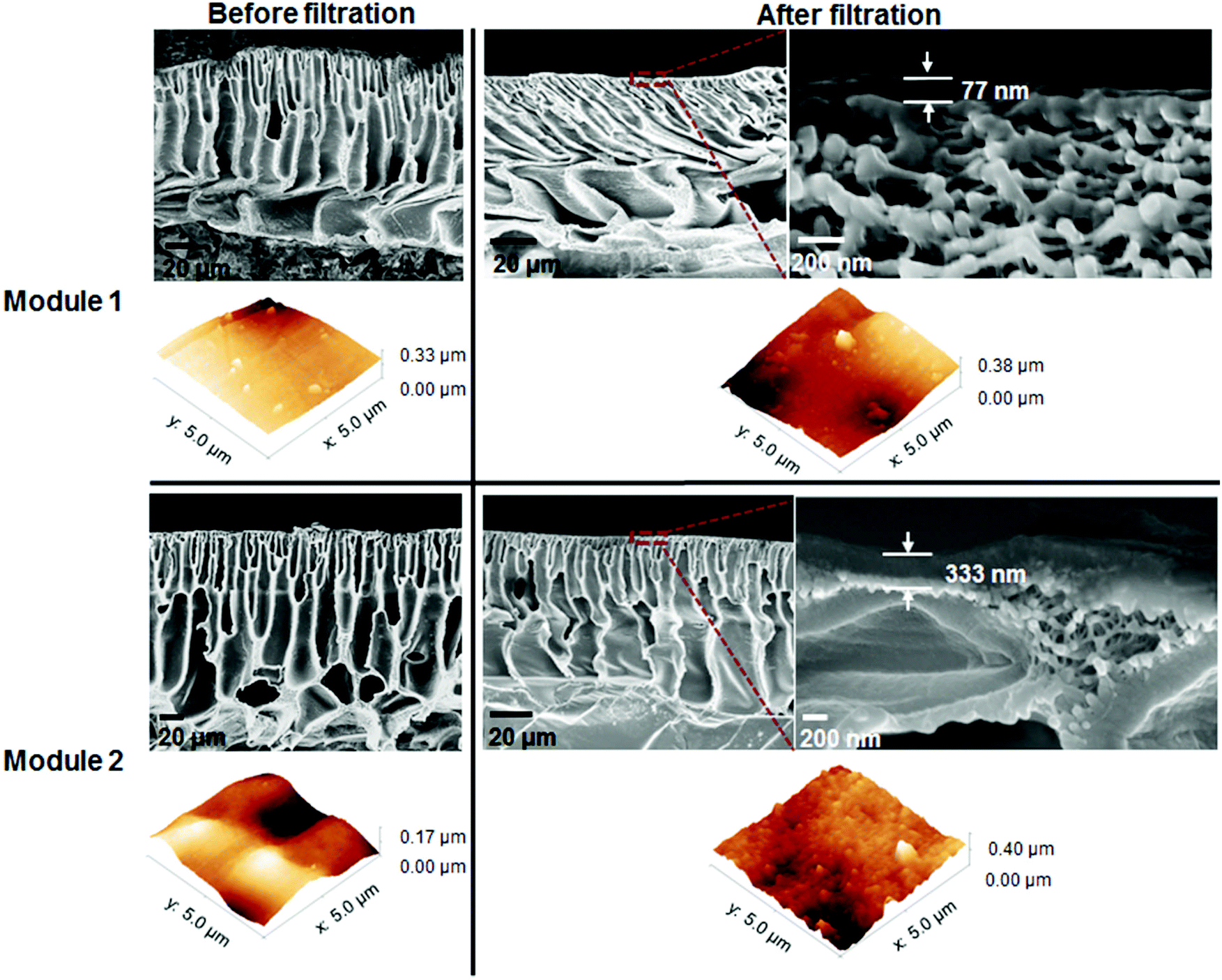 | ||
| Fig. 8 Cross-sectional SEM images and AFM topographical images of membranes M2 (used to produce Module 1) and M3 (used to produce Module 2) before and after module testing revealing changes in overall membrane thickness, surface roughness and different separating layer thicknesses. | ||
| Membrane code | Overall thickness (μm) | Separating layer thickness (nm) | Average roughness (Ra) (nm) | Root-mean-square roughness (Rrms) (nm) |
|---|---|---|---|---|
| M2 before filtration | 128 ± 10 | — | 40.9 | 54.6 |
| M2 after filtration | 80 ± 4 | 176 ± 50 | 47.8 | 63.4 |
| M3 before filtration | 150 ± 24 | — | 30.1 | 37.3 |
| M3 after filtration | 80 ± 5 | 230 ± 68 | 44.1 | 54.8 |
The non-uniformity of the module separating layer suggests that up-scaling of the PEEK membrane is not a straight forward procedure and further research and optimisation is required. Nevertheless, these results successfully proved the scalability of PEEK OSN membranes. In addition the PEEK membrane modules proved to be quite robust. In general to stay reusable, polymeric membrane modules have to be stored in a solvent. However, Module 1 was deliberately left to dry out after the first filtration and then used again (Fig. 7B) showing only a slight decrease in permeance, 0.41 L h−1 m−2 bar−1vs. 0.47 L h−1 m−2 bar−1 (before drying, Fig. 7A).
3.3 The overall “greenness” of PEEK membrane
Although PEEK membranes are apparently a greener alternative from the production point of view, it is also important to assess environmental impact from the application point of view. In this section a comparison between the module area of PEEK and P84 required for permeating 100 L h−1 of THF at 30 bar is performed in terms of its environmental burden. The permeance of PEEK modules considered was 0.47 L h−1 m−2 bar−1 (Module 1) and 0.26 L h−1 m−2 bar−1 (Module 2), and the permeance of P84 standard method was 0.22 L h−1 m−2 bar−1 (data obtained from crosslinked P84 flat sheet membranes with a MWCO of 300 g mol−1). However, a value of 2.33 L h−1 m−2 bar−1 was found in literature for DuraMem® 300 modules32 (PI based membranes). For fairness of comparison both permeances were considered in computing the total waste generated and the total waste cost. The area required for PEEK Module 1 to permeate 100 L h−1 at 30 bar is 7.09 m2, for PEEK Module 2 is 12.82 m2, for P84 low permeance is 15.15 m2 and for P84 high permeance is 1.43 m2. In order to calculate the mass of membrane required (and therefore the corresponding waste composition excluding water) for permeating 100 L h−1 of THF, the area of membrane is multiplied by the thickness and film density. The results are presented in Fig. 9. As expected PEEK has on average 13 times lower total waste than the average total waste of P84 membranes (both low and high permeance), 2.2 kg vs. 29 kg. This difference is mainly because in the production of PEEK membranes only MSA and SA will be present in the waste water stream. In the production of P84 membranes besides DMF and 1,4-dioxane there will be cross-linker and IPA (impregnating solvent) in the waste water stream, thus increasing the total waste generated. Analysing the total waste cost PEEK is presented as a viable green option with an average total waste cost 5.6 times lower than the average total waste cost of P84 membranes, 13.5 vs. 76.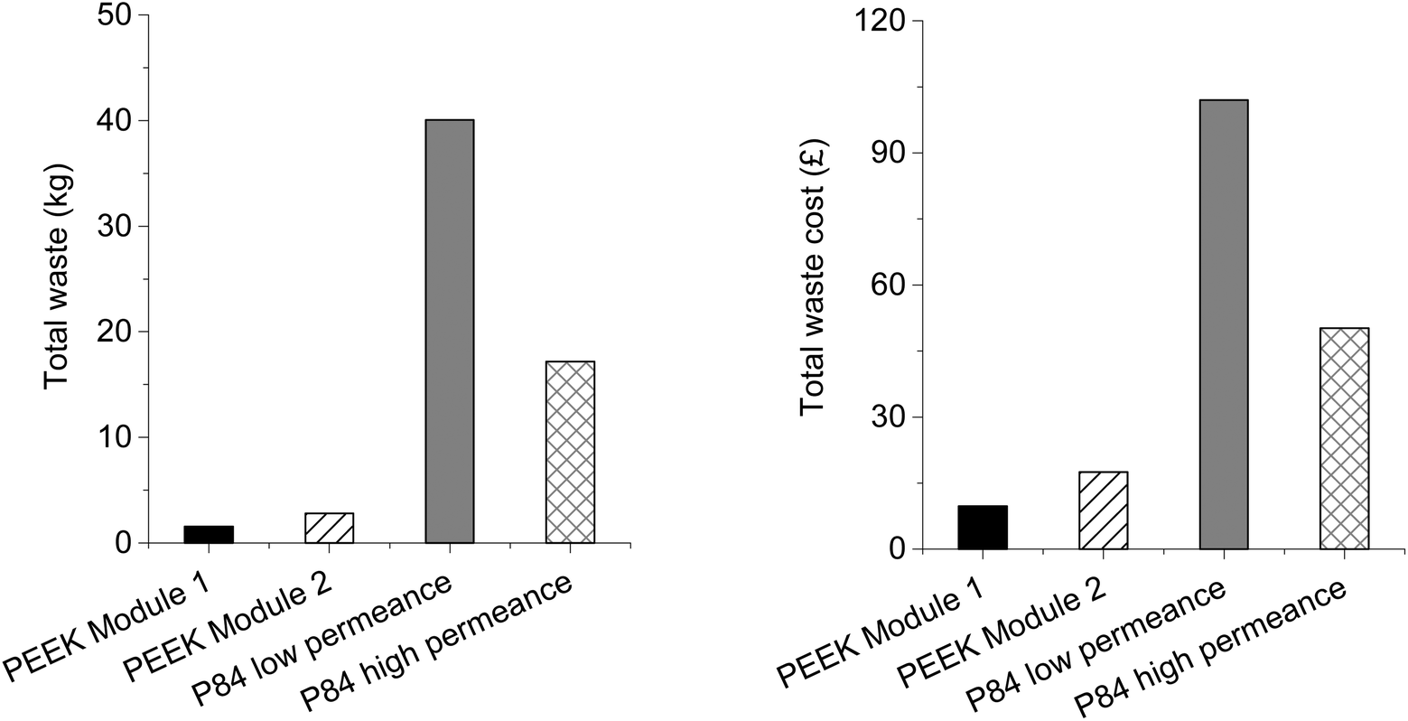 | ||
| Fig. 9 Total waste generated (left), kg, and total waste cost treatment (right), £, for PEEK membranes and P84 membranes (standard method) calculated using the membrane area required to permeate 100 L h−1 of THF at 30 bar pressure. | ||
4 Conclusions
In terms of their manufacturing process and waste-treatment cost PEEK membranes are an environmentally friendly choice when compared with other common OSN membranes such as polyimide based membranes. In our study a comparison was performed at bench and industrial scales with three methods of producing polyimide P84 cross-linked membranes: the “traditional” method; the green method and the SIM method. Calculating the E-factor and the solvent intensity in order to compare the different membrane production it was possible to conclude that PEEK membrane manufacturing has a much lower environmental burden. PEEK had a solvent intensity of 8.3 whereas P84 production methods had values in the range of 35 to 224. For the total waste generated per m2 of membrane area (industrial scale) PEEK is by far the greenest with a total waste produced of 0.21 kg m−2 of membrane whereas P84 traditional method generated 6.58 kg m−2 of membrane; the SIM method and the green method had similar values of 2.23 and 2.98 kg m−2 of membrane, respectively. As a result, PEEK had a low waste cost per kg of polymer of around 46 £ kg−1 of polymer, 22.2 and 4.1 times lower (in average) than P84 methods at bench and industrial scales, respectively. In order to have data for module performance, scaling up of the PEEK membrane to spiral-wound modules was undertaken and data for two modules were presented. Module 1 showed permeance of 0.47 L h−1 m−2 bar−1 and Module 2 permeance of 0.26 L h−1 m−2 bar−1 but the rejection was similar for both modules, ∼300 g mol−1. These differences in permeance were attributed to the different thicknesses of the separating layer and surface area originating from the different casting speeds used for casting membranes for Module 1 and Module 2. Finally, the overall greenness of PEEK was determined in order to assess the environmental burden of permeating 100 L h−1 of THF. As a comparison P84 module data were obtained and total waste (kg) and total waste cost (£) were calculated. The solvent intensity was 13 times lower, in average, than P84 modules, 2.2 vs. 29, and the total waste cost 5.6 times lower, in average, than P84 modules (low and high permeance).PEEK can be a greener alternative than conventional PI modules in the OSN field although optimization work in scaling-up is required to obtain more consistent membrane performances.
Acknowledgements
This work was funded by the Novartis Pharma AG, Massachusetts Institute of Technology sub-award agreement No. 5710002924. The authors would like to acknowledge EPSRC for the financial support under the project EP/J014974/1 entitled Molecular Builders: Constructing Nanoporous Materials.References
- T. B. Hofstetter, C. Capello and K. Hungerbühler, Process Saf. Environ. Prot., 2003, 81, 189–202 CrossRef CAS
.
- A. Amelio, G. Genduso, S. Vreysen, P. Luis and B. Van der Bruggen, Green Chem., 2014, 16, 3045–3063 RSC
- A. Figoli, T. Marino, S. Simone, E. Di Nicolo, X. M. Li, T. He, S. Tornaghi and E. Drioli, Green Chem., 2014, 16, 4034–4059 RSC
-
P. T. W. Anastas and J. C. Warner, Green Chemistry: Theory and Practice, 1998 Search PubMed
- E. Drioli, A. Brunetti, G. Di Profio and G. Barbieri, Green Chem., 2012, 14, 1561–1572 RSC
- G. Szekely, M. F. Jimenez-Solomon, P. Marchetti, J. F. Kim and A. G. Livingston, Green Chem., 2014, 16, 4440–4473 RSC
- J. F. Kim, G. Szekely, I. B. Valtcheva and A. G. Livingston, Green Chem., 2014, 16, 133–145 RSC
- P. Marchetti, M. F. Jimenez Solomon, G. Szekely and A. G. Livingston, Chem. Rev., 2014, 114, 10735–10806 CrossRef CAS PubMed
- L. Peeva, J. D. S. Burgal, I. Valtcheva and A. G. Livingston, Chem. Eng. Sci., 2014, 116, 183–194 CrossRef CAS
- B. Van der Bruggen, M. Mänttäri and M. Nyström, Sep. Purif. Technol., 2008, 63, 251–263 CrossRef CAS
- N. Benmouhoub, N. Simmonet, N. Agoudjil and T. Coradin, Green Chem., 2008, 10, 957–964 RSC
- C. Sanchez, H. Arribart and M. M. Giraud Guille, Nat. Mater., 2005, 4, 277–288 CrossRef CAS PubMed
- M. Darder, P. Aranda and E. Ruiz-Hitzky, Adv. Mater., 2007, 19, 1309–1319 CrossRef CAS
- K. Vanherck, G. Koeckelberghs and I. F. J. Vankelecom, Prog. Polym. Sci., 2013, 38, 874–896 CrossRef CAS
- Y. H. See Toh, X. X. Loh, K. Li, A. Bismarck and A. G. Livingston, J. Membr. Sci., 2007, 291, 120–125 CrossRef
- Y. H. See Toh, F. W. Lim and A. G. Livingston, J. Membr. Sci., 2007, 301, 3–10 CrossRef
- I. B. Valtcheva, S. C. Kumbharkar, J. F. Kim, Y. Bhole and A. G. Livingston, J. Membr. Sci., 2014, 457, 62–72 CrossRef CAS
- C. Jimenez-Gonzalez, D. J. C. Constable and C. S. Ponder, Chem. Soc. Rev., 2012, 41, 1485–1498 RSC
- R. K. Henderson, C. Jimenez-Gonzalez, D. J. C. Constable, S. R. Alston, G. G. A. Inglis, G. Fisher, J. Sherwood, S. P. Binks and A. D. Curzons, Green Chem., 2011, 13, 854–862 RSC
- V. Freger and S. Srebnik, J. Appl. Polym. Sci., 2003, 88, 1162–1169 CrossRef CAS
-
J. E. Cadotte, Interfacially synthesized reverse osmosis membrane, US Patent4,277,344, 1981 Search PubMed
- I. Soroko, Y. Bhole and A. G. Livingston, Green Chem., 2011, 13, 162–168 RSC
- K. Vanherck, A. Cano-Odena, G. Koeckelberghs, T. Dedroog and I. Vankelecom, J. Membr. Sci., 2010, 353, 135–143 CrossRef CAS
- K. Hendrix, K. Vanherck and I. F. J. Vankelecom, J. Membr. Sci., 2012, 421–422, 15–24 CrossRef CAS
- Y. Medina-Gonzalez, P. Aimar, J. F. Lahitte and J. C. Remigy, Int. J. Sustainable Eng., 2010, 4, 75–83 CrossRef
-
C. R. Cannon, Cellulose acetate membranes, US Patent 3,460,683, 1969 Search PubMed
- M.-M. Tao, F. Liu, B.-R. Ma and L.-X. Xue, Desalination, 2013, 316, 137–145 CrossRef CAS
- D. Y. Xing, S. Y. Chan and T.-S. Chung, Green Chem., 2014, 16, 1383–1392 RSC
- J. da Silva Burgal, L. G. Peeva, S. Kumbharkar and A. Livingston, J. Membr. Sci., 2015, 479, 105–116 CrossRef CAS
- L. Peeva, J. da Silva Burgal, S. Vartak and A. G. Livingston, J. Catal., 2013, 306, 190–201 CrossRef CAS
- C. Capello, S. Hellweg and K. Hungerbühler, J. Ind. Ecol., 2008, 12, 111–127 CrossRef
- I. Sereewatthanawut, F. W. Lim, Y. S. Bhole, D. Ormerod, A. Horvath, A. T. Boam and A. G. Livingston, Org. Process Res. Dev., 2010, 14, 600–611 CrossRef CAS
| This journal is © The Royal Society of Chemistry 2016 |